spark plugs FORD FIESTA 1989 Service Owner's Manual
[x] Cancel search | Manufacturer: FORD, Model Year: 1989, Model line: FIESTA, Model: FORD FIESTA 1989Pages: 296, PDF Size: 10.65 MB
Page 139 of 296
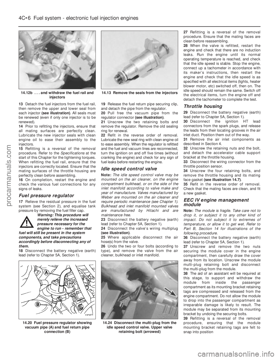
13Detach the fuel injectors from the fuel rail,
then remove the upper and lower seal from
each injector (see illustration) . All seals must
be renewed (even if only one injector is to be
renewed).
14 Prior to refitting the injectors, ensure that
all mating surfaces are perfectly clean.
Lubricate the new injector seals with clean
engine oil to ease their assembly to the
injectors.
15 Refitting is a reversal of the removal
procedure. Refer to the Specificationsat the
start of this Chapter for the tightening torques.
When refitting the fuel rail, ensure that the
injectors are correctly located. Ensure that the
mating surfaces of the throttle housing are
perfectly clean before assembling.
16 On completion, restart the engine and
check the various fuel connections for any
signs of leaks.
Fuel pressure regulator
17 Relieve the residual pressure in the fuel
system (see Section 2), and equalise tank
pressure by removing the fuel filler cap. Warning: This procedure will
merely relieve the increased
pressure necessary for the
engine to run - remember that
fuel will still be present in the system
components, and take precautions
accordingly before disconnecting any of
them.
18 Disconnect the battery negative (earth)
lead (refer to Chapter 5A, Section 1). 19
Release the fuel return pipe securing clip,
and detach the pipe from the regulator.
20 Pull free the vacuum pipe from the
regulator connector (see illustration).
21 Unscrew the two retaining bolts and
remove the regulator. Remove the old sealing
ring for renewal.
22 Refit in the reverse order of removal.
Lubricate the new seal ring with clean engine oil
to ease assembly. When the regulator is refitted
and the fuel and vacuum lines are reconnected,
turn the ignition on and off five times (without
cranking the engine) and check for any sign of
fuel leaks before restarting the engine.
Idle speed control valve
Note: The idle speed control valve may be
mounted on the air cleaner, on the engine
compartment bulkhead, or on the side of the
inlet manifold according to valve make and
year of manufacture. Valves manufactured by
Weber are mounted on the air cleaner and
require periodic maintenance (see Chapter 1).
Bulkhead and inlet manifold mounted valves
are manufactured by Hitachi and are
maintenance free.
23 Disconnect the battery negative (earth)
lead (refer to Chapter 5A, Section 1).
24 Disconnect the valve’s wiring multiplug
(see illustration) .
25 Where applicable disconnect the air
hose(s) from the valve.
26 Undo the two or four bolts (according to
type), and remove the valve from the air
cleaner, bulkhead or inlet manifold. 27
Refitting is a reversal of the removal
procedure. Ensure that the mating faces are
clean before reassembling.
28 When the valve is refitted, restart the
engine and check that there are no induction
leaks. Run the engine until its normal
operating temperature is reached, and check
that the idle speed is stable. Stop the engine,
connect up a tachometer in accordance with
its maker’s instructions, then restart the
engine and check that the idle speed is as
specified with all electrical items (lights, heater
blower motor, etc) switched off, then on. The
idle speed should remain the same. Switch off
the electrical items, turn the engine off and
detach the tachometer to complete the test.
Throttle housing
29 Disconnect the battery negative (earth)
lead (refer to Chapter 5A, Section 1).
30 Disconnect the ignition HT lead
connectors from the spark plugs, and release
the leads from their locating grooves in the air
inlet duct. Position them out of the way.
31 Remove the air inlet components as
described in Section 4.
32 Unscrew the retaining nuts and the bolt,
and detach the accelerator cable support
bracket at the throttle housing.
33 Disconnect the wiring connector from the
throttle position sensor.
34 Unscrew the four retaining bolts, and
remove the throttle housing and its mating
face gasket (see illustration 14.7) .
35 Refit in the reverse order of removal.
Check that the mating faces are clean, and fit
a new gasket.
EEC IV engine management
module
Note: The module is fragile. Take care not to
drop it, or subject it to any other kind of
impact. Do not subject it to extremes of
temperature, or allow it to get wet. Refer to
Part B, Section 14 for illustrations of the
following procedure.
36 Disconnect the battery negative (earth)
lead (refer to Chapter 5A, Section 1).
37 Unscrew and remove the two nuts
securing the module cover in the engine
compartment, then carefully draw the cover
away from its location. Unscrew the module
multi-plug retaining bolt and disconnect
the multi-plug from the module.
38 The aid of an assistant will be required at
this stage, to support and withdraw the
module from inside the passenger
compartment as its mounting bracket retaining
tags are compressed and released from the
engine compartment. Do not allow the module
to drop into the passenger compartment as
irreparable damage is likely to result. The
module may be separated from its mounting
bracket by undoing the securing bolts.
39 Refitting is a reversal of the removal
procedure, ensuring that the module
mounting bracket retaining tags are felt to
snap into position
4C•6 Fuel system - electronic fuel injection engines
14.24 Disconnect the multi-plug from the idle speed control valve. Upper valve
retaining bolt (arrowed)14.20 Fuel pressure regulator showingvacuum pipe (A) and fuel return pipe
connection (B)
14.13 Remove the seals from the injectors14.12b . . . and withdraw the fuel rail and injectors
1595Ford Fiesta Remakeprocarmanuals.com
http://vnx.su
Page 146 of 296
4 Air cleaner assembly and airinlet components - removal
and refitting
1
Air cleaner assembly
1 Disconnect the battery negative (earth) lead
(refer to Chapter 5A, Section 1).
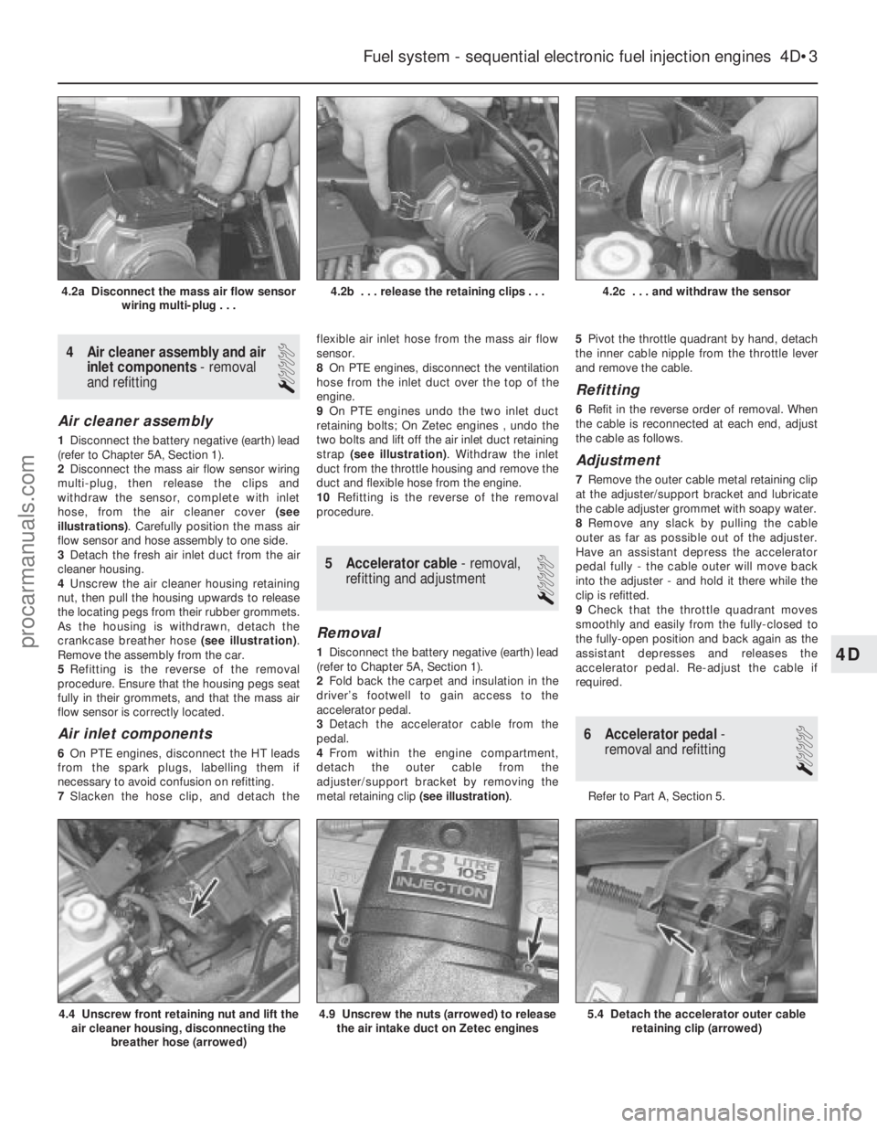
2 Disconnect the mass air flow sensor wiring
multi-plug, then release the clips and
withdraw the sensor, complete with inlet
hose, from the air cleaner cover (see
illustrations) . Carefully position the mass air
flow sensor and hose assembly to one side.
3 Detach the fresh air inlet duct from the air
cleaner housing.
4 Unscrew the air cleaner housing retaining
nut, then pull the housing upwards to release
the locating pegs from their rubber grommets.
As the housing is withdrawn, detach the
crankcase breather hose (see illustration).
Remove the assembly from the car.
5 Refitting is the reverse of the removal
procedure. Ensure that the housing pegs seat
fully in their grommets, and that the mass air
flow sensor is correctly located.
Air inlet components
6 On PTE engines, disconnect the HT leads
from the spark plugs, labelling them if
necessary to avoid confusion on refitting.
7 Slacken the hose clip, and detach the flexible air inlet hose from the mass air flow
sensor.
8
On PTE engines, disconnect the ventilation
hose from the inlet duct over the top of the
engine.
9 On PTE engines undo the two inlet duct
retaining bolts; On Zetec engines , undo the
two bolts and lift off the air inlet duct retaining
strap (see illustration) . Withdraw the inlet
duct from the throttle housing and remove the
duct and flexible hose from the engine.
10 Refitting is the reverse of the removal
procedure.
5 Accelerator cable - removal,
refitting and adjustment
1
Removal
1 Disconnect the battery negative (earth) lead
(refer to Chapter 5A, Section 1).
2 Fold back the carpet and insulation in the
driver’s footwell to gain access to the
accelerator pedal.
3 Detach the accelerator cable from the
pedal.
4 From within the engine compartment,
detach the outer cable from the
adjuster/support bracket by removing the
metal retaining clip (see illustration).5
Pivot the throttle quadrant by hand, detach
the inner cable nipple from the throttle lever
and remove the cable.
Refitting
6 Refit in the reverse order of removal. When
the cable is reconnected at each end, adjust
the cable as follows.
Adjustment
7 Remove the outer cable metal retaining clip
at the adjuster/support bracket and lubricate
the cable adjuster grommet with soapy water.
8 Remove any slack by pulling the cable
outer as far as possible out of the adjuster.
Have an assistant depress the accelerator
pedal fully - the cable outer will move back
into the adjuster - and hold it there while the
clip is refitted.
9 Check that the throttle quadrant moves
smoothly and easily from the fully-closed to
the fully-open position and back again as the
assistant depresses and releases the
accelerator pedal. Re-adjust the cable if
required.
6 Accelerator pedal -
removal and refitting
1
Refer to Part A, Section 5.
Fuel system - sequential electronic fuel injection engines 4D•3
4.2c . . . and withdraw the sensor4.2b . . . release the retaining clips . . .4.2a Disconnect the mass air flow sensor
wiring multi-plug . . .
5.4 Detach the accelerator outer cableretaining clip (arrowed)4.9 Unscrew the nuts (arrowed) to releasethe air intake duct on Zetec engines4.4 Unscrew front retaining nut and lift theair cleaner housing, disconnecting the
breather hose (arrowed)
4D
1595Ford Fiesta Remakeprocarmanuals.com
http://vnx.su
Page 169 of 296
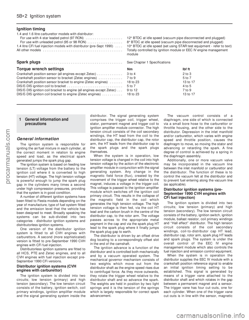
Ignition timing
1.4 and 1.6 litre carburettor models with distributor:For use with 4-star leaded petrol (97 RON) . . . . . . . . . . . . . . . . . . . . 12°BTDC at idle speed (vacuum pipe disconnected and plugged)
For use with unleaded petrol (95 or 98 RON) . . . . . . . . . . . . . . . . . . . 8° BTDC at idle speed (vacuum pipe disconnected and plugged)
1.4 litre CFi fuel injection models with distributor (pre-Sept 1990) . . . . 10°BTDC at idle speed (set using STAR test equipment - refer to text)
All other models . . . . . . . . . . . . . . . . . . . . . . . . . . . . . . . . . . . .\
. . . . . . . Totally controlled by ignition module or EEC IV engine management module
Spark plugs . . . . . . . . . . . . . . . . . . . . . . . . . . . . . . . . . . . .\
. . . . . . . See Chapter 1 Specifications
Torque wrench settingsNmlbf ft
Crankshaft position sensor (all engines except Zetec) . . . . . . . . . . . . . . 3 to 4 2 to 3
Crankshaft position sensor to bracket (Zetec engines) . . . . . . . . . . . . . 7 to 9 5 to 7
Crankshaft position sensor bracket to engine (Zetec engines) . . . . . . . 18 to 23 13 to 17
DIS/E-DIS ignition coil to bracket . . . . . . . . . . . . . . . . . . . . . . . . . . . . . . 5 to 7 4 to 5
DIS/E-DIS ignition coil bracket to engine (all engines except Zetec) . . . 9 to 12 7 to 9
DIS/E-DIS ignition coil bracket to engine (Zetec engines) . . . . . . . . . . . 18 to 23 13 to 17
5B•2 Ignition system
1595Ford Fiesta Remake
1 General information and
precautions
General information
The ignition system is responsible for
igniting the air/fuel mixture in each cylinder, at
the correct moment in relation to engine
speed and load, as the electrical spark
generated jumps the spark plug gap. The ignition system is based on feeding low
tension (LT) voltage from the battery to the
ignition coil where it is converted to high
tension (HT) voltage. The high tension voltage
is powerful enough to jump the spark plug
gap in the cylinders many times a second
under high compression pressures, providing
that the system is in good condition. A number of different ignition systems have
been fitted to Fiesta models depending on the
year of manufacture, type of fuel system fitted
and the emission level that the vehicle has
been designed to meet. Broadly speaking the
systems can be sub-divided into two
categories - distributor ignition systems and
distributorless ignition systems. One version of the distributor ignition
system is fitted to all CVH engines with
carburettors. A second (more sophisticated)
version is fitted to pre-September 1990 CVH
engines with CFi fuel injection. Distributorless ignition systems are fitted to
all HCS, PTE and Zetec engines, and to all
CVH engines with fuel injection except pre-
September 1990 CFi versions.
Distributor ignition systems (CVH
engines with carburettor)
The ignition system is divided into two
circuits; low tension (primary) and high
tension (secondary). The low tension circuit
consists of the battery, ignition switch, coil
primary windings, ignition amplifier module
and the signal generating system inside the distributor. The signal generating system
comprises the trigger coil, trigger wheel,
stator, permanent magnet and trigger coil to
ignition amplifier module connector. The high
tension circuit consists of the coil secondary
windings, the HT lead from the coil to the
distributor cap, the distributor cap, the rotor
arm, the HT leads from the distributor cap to
the spark plugs and the spark plugs
themselves.
When the system is in operation, low
tension voltage is changed in the coil into high
tension voltage by the action of the electronic
amplifier module in conjunction with the signal
generating system. Any change in the
magnetic field force (flux), created by the
movement of the trigger wheel relative to the
magnet, induces a voltage in the trigger coil.
This voltage is passed to the ignition amplifier
module which switches off the ignition coil
primary circuit. This results in the collapse of
the magnetic field in the coil which
generates the high tension voltage. The high
tension voltage is then fed, via the coil HT
lead and the carbon brush in the centre of the
distributor cap, to the rotor arm. The voltage
passes across to the appropriate metal
segment in the cap and via the spark plug HT
lead to the spark plug where it finally jumps
the spark plug gap to earth. The distributor is driven by an offset drive
dog locating to a correspondingly offset slot
in the end of the camshaft.
The ignition advance is a function of the
distributor and is controlled both mechanically
and by a vacuum operated system. The
mechanical governor mechanism consists of
two weights which move out from the
distributor shaft as the engine speed rises due
to centrifugal force. As they move outwards,
they rotate the trigger wheel relative to the
distributor shaft and so advance the spark.
The weights are held in position by two light
springs and it is the tension of the springs
which is largely responsible for correct spark
advancement. The vacuum control consists of a
diaphragm, one side of which is connected
via a small bore hose to the carburettor or
throttle housing, and the other side to the
distributor. Depression in the inlet manifold
and/or carburettor, which varies with engine
speed and throttle position, causes the
diaphragm to move, so moving the stator and
advancing or retarding the spark. A fine
degree of control is achieved by a spring in
the diaphragm assembly. Additionally, one or more vacuum valve
may be incorporated in the vacuum line
between the inlet manifold or carburettor and
the distributor. The function of these is to
control the vacuum felt at the distributor and
to prevent fuel entering along the vacuum line
(as applicable).
Distributor ignition systems (pre-
September 1990 CVH engines with
CFi fuel injection)
The ignition system is divided into two
circuits; low tension (primary) and high
tension (secondary). The low tension circuit
consists of the battery, ignition switch, ignition
module, ballast resistor, coil primary windings
and “Hall effect” distributor. The high tension
circuit consists of the coil secondary
windings, coil-to-distributor cap HT lead,
distributor cap, rotor arm, spark plug HT leads
and spark plugs. The system is under the
overall control of the EEC IV engine
management module which also controls the
fuel injection and emission control equipment. When the system is in operation the
distributor supplies the EEC IV module with a
crankshaft position reference signal to enable
an initial ignition timing setting to be
established. This signal is generated by
means of a trigger vane attached to the
distributor shaft and which rotates in the gap
between a permanent magnet and a sensor.
The trigger vane has four cut-outs, one for
each cylinder. When one of the trigger vane
cut-outs is in line with the sensor, magnetic
procarmanuals.com
http://vnx.su
Page 170 of 296
flux can pass between the magnet and the
sensor. When a trigger vane segment is in line
with the sensor, the magnetic flux is diverted
through the trigger vane, away from the
sensor. The sensor detects the change in
magnetic flux and sends an impulse to the
EEC IV module. Additional data is received
from the engine coolant temperature sensor,
manifold absolute pressure sensor, inlet air
temperature sensor, throttle position sensor
and vehicle speed sensor. Using this
information the EEC IV module calculates the
optimum ignition advance setting and
switches off the low tension circuit via the
ignition module. This results in the collapse of
the magnetic field in the coil which generates
the high tension voltage. The high tension
voltage is then fed, via the coil HT lead and
the carbon brush in the centre of the
distributor cap, to the rotor arm. The voltage
passes across to the appropriate metal
segment in the cap and via the spark plug HT
lead to the spark plug where it finally jumps
the spark plug gap to earth. It can be seen
that the ignition module functions basically as
a high current switch by controlling the low
tension supply to the ignition coil primary
windings.In the event of failure of a sensor, the
EEC IV module will substitute a preset value
for that input to allow the system to continue
to function. In the event of failure of the
EEC IV module, a “limited operation strategy”
(LOS) function allows the vehicle to be driven,
albeit at reduced power and efficiency. The
EEC IV module also has a “keep alive
memory” (KAM) function which stores idle and
drive values and codes which can be used to
indicate any system fault which may occur.
Distributorless ignition systems
The main ignition system components
include the ignition switch, the battery, the
crankshaft speed/position sensor, the ignition
module, the coil, the primary (low tension/LT)
and secondary (high tension/HT) wiring
circuits, and the spark plugs. The system used on carburettor models is
termed DIS (Distributorless Ignition System),
and on fuel injection models E-DIS, (Electronic
Distributorless Ignition System). The primary
difference between the two is that the DIS
system is an independent ignition control
system while the E-DIS system operates in
conjunction with the EEC IV engine
management module which also controls the
fuel injection and emission control systems.
With both systems, the main functions of
the distributor are replaced by a computerised
ignition module and a coil unit. The coil unit
combines a double-ended pair of coils - each
time a coil receives an ignition signal, two
sparks are produced, at each end of the
secondary windings. One spark goes to a
cylinder on compression stroke and the other
goes to the corresponding cylinder on its
exhaust stroke. The first will give the correct power stroke, but the second spark will have
no effect (a “wasted spark”), occurring as it
does during exhaust conditions.
The ignition signal is generated by a
crankshaft position sensor which scans a
series of 36 protrusions on the periphery of
the engine flywheel. The inductive head of the
crankshaft position sensor runs just above the
flywheel periphery and as the crankshaft
rotates, the sensor transmits a pulse to the
ignition module every time a protrusion
passes it. There is one missing protrusion in
the flywheel periphery at a point
corresponding to 90° BTDC. The ignition
module recognises the absence of a pulse
from the crankshaft position sensor at this
point to establish a reference mark for
crankshaft position. Similarly, the time interval
between absent pulses is used to determine
engine speed. On carburettor engines, the ignition module
receives signals provided by information
sensors which monitor various engine
functions (such as crankshaft position,
coolant temperature, inlet air temperature,
inlet manifold vacuum etc). This information
allows the ignition module to generate the
optimum ignition timing setting under all
operating conditions.
On fuel injection engines, the ignition
module operates in conjunction with the
EEC IV engine management module, and
together with the various additional
information sensors and emission control
components, provides total control of the fuel
and ignition systems to form a complete
engine management package. The information contained in this Chapter
concentrates on the ignition-related
components of the engine management
system. Information covering the fuel, exhaust
and emission control components can be
found in the applicable Parts of Chapter 4.
Precautions
When working on the ignition system, take
the following precautions:
a) Do not keep the ignition switch on for
more than 10 seconds if the engine will
not start.
b) If a separate tachometer is ever required
for servicing work, consult a dealer
service department before buying a
tachometer for use with this vehicle -
some tachometers may be incompatible
with these types of ignition systems - and
always connect it in accordance with the
equipment manufacturer’s instructions.
c) Never connect the ignition coil terminals to earth. This could result in damage to
the coil and/or the ignition module.
d) Do not disconnect the battery when the
engine is running.
e) Make sure that the ignition module is
properly earthed.
f) Refer to the warning at the beginning of the next Section concerning HT voltage.
2 Ignition system - testing
2
Warning: Voltages produced by
an electronic ignition system are
considerably higher than those
produced by conventional
ignition systems. Extreme care must be
taken when working on the system with
the ignition switched on. Persons with
surgically-implanted cardiac pacemaker
devices should keep well clear of the
ignition circuits, components and test
equipment.
Note: Refer to the precautions given in
Section 1 of Part A of this Chapter before
starting work. Always switch off the ignition
before disconnecting or connecting any
component and when using a multi-meter to
check resistances.
1 If the engine turns over but won’t start,
disconnect the (HT) lead from any spark plug,
and attach it to a calibrated tester (available at
most automotive accessory shops). Connect
the clip on the tester to a good earth - a bolt
or metal bracket on the engine. If you’re
unable to obtain a calibrated ignition tester,
have the check carried out by a Ford dealer
service department or similar. Any other form
of testing (such as jumping a spark from the
end of an HT lead to earth) is not
recommended, because of the risk of
personal injury, or of damage to the ignition
module.
2 Crank the engine, and watch the end of the
tester to see if bright blue, well-defined sparks
occur.
3 If sparks occur, sufficient voltage is
reaching the plug to fire it. Repeat the
check at the remaining plugs, to ensure
that all leads are sound and that the
coil is serviceable. However, the plugs
themselves may be fouled or faulty, so
remove and check them as described in
Chapter 1.
4 If no sparks or intermittent sparks occur,
the spark plug lead(s) may be defective. Also,
on distributor systems, there may be
problems with the rotor arm or distributor cap
- check all these components as described in
Chapter 1.
5 If there’s still no spark, check the coil’s
electrical connector (where applicable), to
make sure it’s clean and tight. Check for full
battery voltage to the coil at the connector’s
centre terminal. Check the coil itself (see
Section 3). Make any necessary repairs, then
repeat the check again.
6 The remainder of the system checks should
be left to a dealer service department
or other qualified repair facility, as there is a
chance that the ignition module may
be damaged if tests are not performed
properly.
Ignition system 5B•3
5B
1595Ford Fiesta Remakeprocarmanuals.com
http://vnx.su
Page 171 of 296

3 Ignition coil- checking,
removal and refitting
2
Distributor ignition systems
Checking
1 Accurate checking of the coil output
requires the use of special test equipment and
should be left to a dealer or suitably equipped
automotive electrician. It is however possible
to check the primary and secondary winding
resistance using an ohmmeter as follows.
2 Disconnect the battery negative (earth) lead
(refer to Part A, Section 1).
3 Remove the vehicle jack from its storage
position by unscrewing its retainer. The
ignition coil is mounted below.
4 To check the primary resistance (with all
leads disconnected if the coil is fitted),
connect the ohmmeter across the coil positive
and negative terminals. The resistance should
be as given in the Specificationsat the
beginning of this Chapter.
5 To check the secondary resistance (with all
leads disconnected if the coil is fitted),
connect one lead from the ohmmeter to the
coil negative terminal, and the other lead to
the centre HT terminal. Again the resistance
should be as given in the Specifications.
6 If any of the measured values vary
significantly from the figures given in the
Specifications , the coil should be renewed.
7 If a new coil is to be fitted, ensure that it is
of the correct type. The appropriate Ford
supplied ignition coil is identified by a red
label, and will be one of three different makes,
all of which are fully interchangeable. Bosch
and Femsa coils are fitted with protective
plastic covers, and Polmot coils are fitted with
an internal fusible link. Note that contact
breaker ignition coils are not interchangeable
with the required breakerless type and could
cause ignition module failure if used.
Removal
8 If not already done, remove the vehicle jack from its storage position by unscrewing its
retainer. The ignition coil is mounted below.
9
Disconnect the battery negative (earth) lead
(refer to Part A, Section 1).
10 Disconnect the HT lead and the low
tension (LT) connections from the ignition coil.
Note that the LT connections on the ignition
coil are of different sizes. As an aid to refitting
the positive (+) terminal is larger than the
negative (-) terminal (see illustration).
11 Remove the two screws or bolts securing
the coil mounting bracket to the inner wing
panel, and withdraw the coil and mounting
bracket assembly.
Refitting
12 Refitting is a reversal of the removal
procedure, ensuring correct LT lead polarity.
Distributorless ignition systems
Checking
Note: The ignition coil is located on the rear
facing side of the cylinder block on HCS
engines; on the left-hand end of the cylinder
head on CVH, PTE and Zetec engines.
13 Having checked that full battery voltage is
available at the centre terminal of the coil’s
electrical connector (see Section 2),
disconnect the battery negative (earth) lead
(refer to Part A, Section 1).
14 Unplug the coil’s electrical connector, if
not already disconnected.
15 Using an ohmmeter, measure the
resistance of the coil’s primary windings,
connecting the meter between the coil’s
terminal pins as follows. Measure first from
one outer pin to the centre pin, then from the
other outer pin to the centre. Compare the
readings with the coil primary resistance listed
in the Specifications .
16 Disconnect the spark plug (HT) leads -
note their connections or label them carefully,
as described in Chapter 1. Use the meter to
check that there is continuity between each
pair of (HT) lead terminals; Nos 1 and 4
terminals are connected by their secondary
winding, as are Nos 2 and 3. Now switch to the highest resistance scale, and check that
there is no continuity between either pair of
terminals and the other - ie, there should be
infinite resistance between terminals 1 and 2,
or 4 and 3 - and between any terminal and
earth.
17
If either of the above tests yield resistance
values outside the specified amount, or
results other than those described, renew the
coil. Any further testing should be left to a
dealer service department or other qualified
repair facility.
Removal
Note: The ignition coil is located on the rear
facing side of the cylinder block on HCS
engines; on the left-hand end of the cylinder
head on CVH, PTE and Zetec engines.
18 Disconnect the battery negative (earth)
lead (refer to Part A, Section 1).
19 Disconnect the coil main electrical
connector and (where fitted) the electrical
connector to the suppressor.
20 The coil can be removed with the HT
leads left attached, in which case disconnect
the leads from their respective spark plugs
and from the location clips in the rocker cover
or air inlet duct (as applicable). If preferred,
the HT leads can be disconnected from the
coil. First check that both the ignition HT
leads and their fitted positions are clearly
marked numerically to ensure correct refitting.
Spot mark them accordingly if necessary,
using quick-drying paint.
21 If disconnecting the leads from the spark
plugs, pull them free by gripping on the
connector, not the lead. To detach the leads
from the ignition coil, compress the retaining
arms of each lead connector at the coil, and
detach each lead in turn (see illustration).
22 Unscrew the Torx-type retaining screws,
and remove the coil from its mounting on the
engine (see illustration) .
Refitting
23Refitting is the reverse of the removal
procedure. Ensure that the spark plug (HT)
leads are correctly reconnected, and tighten
the coil screws securely.
5B•4 Ignition system
3.22 Distributorless ignition system ignition coil and mounting bracket removal (HCS engine shown)3.21 Removing an HT lead from the
distributorless ignition system ignition coil. Note the corresponding markings on the ignition coil and HT lead (arrowed)3.10 Ignition coil fitted to distributor
ignition systems
A Retaining bolts
B LT connections
C HT lead to distributor cap
1595Ford Fiesta Remakeprocarmanuals.com
http://vnx.su
Page 172 of 296

4 Ignition amplifier module(distributor ignition systems)
- removal and refitting
2
Note: The ignition amplifier module is only
fitted to carburettor engine models.
Removal
1 Disconnect the battery negative (earth) lead
(refer to Part A, Section 1).
2 Remove the distributor, as described in
Section 8.
3 With the distributor on the workbench,
remove both screws securing the module to
the distributor body, then slide the module
from its trigger coil connector and remove it.
4 Check that the rubber grommet is
serviceable. If it is not, it must be renewed but
ensure that the correct type is obtained.
Refitting
5 Apply heat sink compound (see
Specifications ) to the module metal face,
ensuring a good earth. This is an essential
part of the procedure, protecting the module
electronic circuitry from excessive heat build-
up and subsequent malfunction.
6 Slide the module into its trigger coil
connector and secure with both screws.
7 Refit the distributor in accordance with
Section 8, then reconnect the battery.
5 Ignition module -
removal and refitting
1
Note: Various designs of ignition module may
be fitted depending on ignition system type.
Although the units may differ in appearance
from the those shown in the accompanying
illustrations, the procedures described below
are applicable to all types.
Removal
1 The ignition module is located on the
engine compartment bulkhead.
2 Disconnect the battery negative (earth) lead
(refer to Part A, Section 1).
3 Where applicable, detach the vacuum hose
from the module (see illustration).
4 According to type, either compress the
locktab securing the wiring multi-plug in
position, or where applicable, undo the
retaining bolt, then withdraw the plug from the
module (see illustrations) .
5 Undo the retaining screws, and remove
the module from the bulkhead (see
illustration) .
Refitting
6Refitting is the reverse of the removal
procedure.
6 Crankshaft position sensor -
removal and refitting
2
Removal
1 Disconnect the battery negative (earth) lead
(refer to Part A, Section 1).
2 Chock the rear wheels then jack up the
front of the car and support it on axle stands
(see “Jacking and vehicle support” ).
3 If working on the Zetec engine, remove the
starter motor as described in Part A of this
Chapter.
4 Compress the retaining clip and pull free
the wiring multi-plug connector from the
sensor unit, but take care to pull on the
connector, not the lead (see illustration).
5 Undo the Torx-type retaining screw, and
withdraw the sensor from its location in the
cylinder block bellhousing flange.
Refitting
6 Refitting is the reversal of removal.
7 Distributor cap and rotor
arm - removal and refitting
1
Removal
1Disconnect the battery negative (earth) lead
(refer to Part A, Section 1).
2 Disconnect the coil HT lead from the centre
of the distributor cap and the spark plug HT
leads from the spark plugs, having identified
them for subsequent refitting. Pull on the
connectors, not the leads. Release the leads
from any cable clips or ties.
3 On carburettor models, unclip the
suppressor shield (where fitted), remove the
distributor cap securing screws and detach
the cap.
4 On CFi fuel injection models, disconnect
the distributor multi-plug for better access to
the rear cap securing clip. Release the
distributor cap securing clips by levering with
a screwdriver, withdraw the cap assembly
Ignition system 5B•5
5.4b Undoing the ignition module multi- plug securing bolt5.4a Disconnecting the ignition module multi-plug5.3 Disconnecting the vacuum pipe fromthe ignition module
6.4 Crankshaft position sensor removal
A Retaining screw B Multi-plug5.5 Ignition module location on bulkheadpanel. Note retaining screws (arrowed)
5B
1595Ford Fiesta Remakeprocarmanuals.com
http://vnx.su
Page 271 of 296
1595 Ford Fiesta Remake
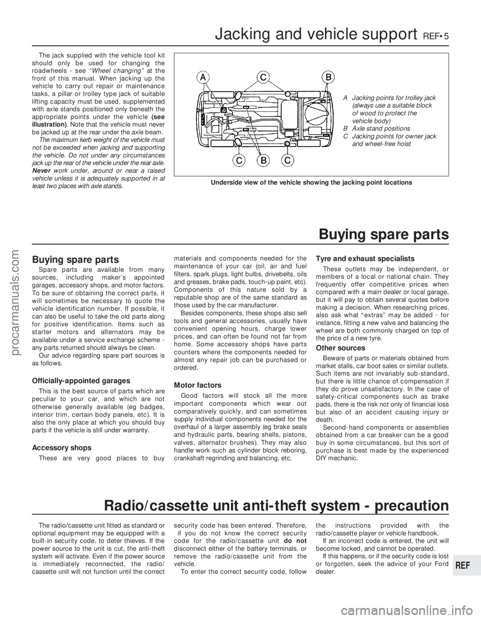
The jack supplied with the vehicle tool kit
should only be used for changing the
roadwheels - see “Wheel changing” at the
front of this manual. When jacking up the
vehicle to carry out repair or maintenance
tasks, a pillar or trolley type jack of suitable
lifting capacity must be used, supplemented
with axle stands positioned only beneath the
appropriate points under the vehicle (see
illustration) . Note that the vehicle must never
be jacked up at the rear under the axle beam. The maximum kerb weight of the vehicle must
not be exceeded when jacking and supporting
the vehicle. Do not under any circumstances
jack up the rear of the vehicle under the rear axle.
Never work under, around or near a raised
vehicle unless it is adequately supported in at
least two places with axle stands.
The radio/cassette unit fitted as standard or
optional equipment may be equipped with a
built-in security code, to deter thieves. If the
power source to the unit is cut, the anti-theft
system will activate. Even if the power source
is immediately reconnected, the radio/
cassette unit will not function until the correct security code has been entered. Therefore,
if you do not know the correct security
code for the radio/cassette unit do not
disconnect either of the battery terminals, or
remove the radio/cassette unit from the
vehicle. To enter the correct security code, follow the instructions provided with the
radio/cassette player or vehicle handbook.
If an incorrect code is entered, the unit will
become locked, and cannot be operated.
If this happens, or if the security code is lost
or forgotten, seek the advice of your Ford
dealer.
Jacking and vehicle supportREF•5
REF
Radio/cassette unit anti-theft system - precaution
Underside view of the vehicle showing the jacking point locations
A Jacking points for trolley jack (always use a suitable block
of wood to protect the
vehicle body)
B Axle stand positions
C Jacking points for owner jack and wheel-free hoist
Buying spare parts
Spare parts are available from many
sources, including maker’s appointed
garages, accessory shops, and motor factors.
To be sure of obtaining the correct parts, it
will sometimes be necessary to quote the
vehicle identification number. If possible, it
can also be useful to take the old parts along
for positive identification. Items such as
starter motors and alternators may be
available under a service exchange scheme -
any parts returned should always be clean.
Our advice regarding spare part sources is
as follows.
Officially-appointed garages
This is the best source of parts which are
peculiar to your car, and which are not
otherwise generally available (eg badges,
interior trim, certain body panels, etc). It is
also the only place at which you should buy
parts if the vehicle is still under warranty.
Accessory shops
These are very good places to buy materials and components needed for the
maintenance of your car (oil, air and fuel
filters, spark plugs, light bulbs, drivebelts, oils
and greases, brake pads, touch-up paint, etc).
Components of this nature sold by a
reputable shop are of the same standard as
those used by the car manufacturer.
Besides components, these shops also sell
tools and general accessories, usually have
convenient opening hours, charge lower
prices, and can often be found not far from
home. Some accessory shops have parts
counters where the components needed for
almost any repair job can be purchased or
ordered.
Motor factors
Good factors will stock all the more
important components which wear out
comparatively quickly, and can sometimes
supply individual components needed for the
overhaul of a larger assembly (eg brake seals
and hydraulic parts, bearing shells, pistons,
valves, alternator brushes). They may also
handle work such as cylinder block reboring,
crankshaft regrinding and balancing, etc.
Tyre and exhaust specialists
These outlets may be independent, or
members of a local or national chain. They
frequently offer competitive prices when
compared with a main dealer or local garage,
but it will pay to obtain several quotes before
making a decision. When researching prices,
also ask what “extras” may be added - for
instance, fitting a new valve and balancing the
wheel are both commonly charged on top of
the price of a new tyre.
Other sources
Beware of parts or materials obtained from
market stalls, car boot sales or similar outlets.
Such items are not invariably sub-standard,
but there is little chance of compensation if
they do prove unsatisfactory. In the case of
safety-critical components such as brake
pads, there is the risk not only of financial loss
but also of an accident causing injury or
death. Second-hand components or assemblies
obtained from a car breaker can be a good
buy in some circumstances, but this sort of
purchase is best made by the experienced
DIY mechanic.
Buying spare parts
procarmanuals.com
http://vnx.su
Page 281 of 296
1595 Ford Fiesta Remake
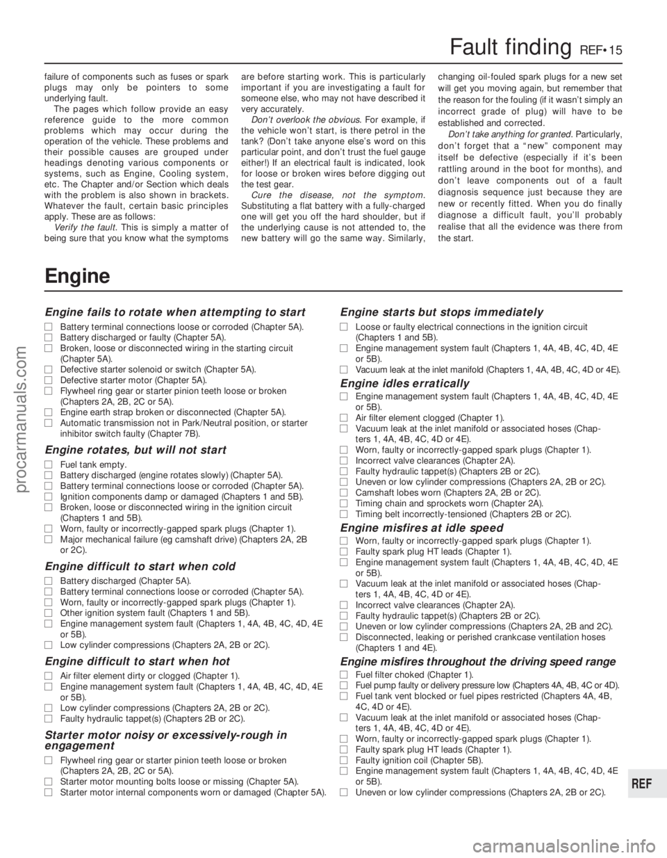
failure of components such as fuses or spark
plugs may only be pointers to some
underlying fault.
The pages which follow provide an easy
reference guide to the more common
problems which may occur during the
operation of the vehicle. These problems and
their possible causes are grouped under
headings denoting various components or
systems, such as Engine, Cooling system,
etc. The Chapter and/or Section which deals
with the problem is also shown in brackets.
Whatever the fault, certain basic principles
apply. These are as follows:
Verify the fault . This is simply a matter of
being sure that you know what the symptoms are before starting work. This is particularly
important if you are investigating a fault for
someone else, who may not have described it
very accurately.
Don’t overlook the obvious . For example, if
the vehicle won’t start, is there petrol in the
tank? (Don’t take anyone else’s word on this
particular point, and don’t trust the fuel gauge
either!) If an electrical fault is indicated, look
for loose or broken wires before digging out
the test gear. Cure the disease, not the symptom .
Substituting a flat battery with a fully-charged
one will get you off the hard shoulder, but if
the underlying cause is not attended to, the
new battery will go the same way. Similarly, changing oil-fouled spark plugs for a new set
will get you moving again, but remember that
the reason for the fouling (if it wasn’t simply an
incorrect grade of plug) will have to be
established and corrected.
Don’t take anything for granted . Particularly,
don’t forget that a “new” component may
itself be defective (especially if it’s been
rattling around in the boot for months), and
don’t leave components out of a fault
diagnosis sequence just because they are
new or recently fitted. When you do finally
diagnose a difficult fault, you’ll probably
realise that all the evidence was there from
the start.
Fault findingREF•15
REF
Engine
Engine fails to rotate when attempting to start
m
m Battery terminal connections loose or corroded (Chapter 5A).
m
m Battery discharged or faulty (Chapter 5A).
m
m Broken, loose or disconnected wiring in the starting circuit
(Chapter 5A).
m m Defective starter solenoid or switch (Chapter 5A).
m
m Defective starter motor (Chapter 5A).
m
m Flywheel ring gear or starter pinion teeth loose or broken
(Chapters 2A, 2B, 2C or 5A).
m m Engine earth strap broken or disconnected (Chapter 5A).
m
m Automatic transmission not in Park/Neutral position, or starter
inhibitor switch faulty (Chapter 7B).
Engine rotates, but will not start
m mFuel tank empty.
m
m Battery discharged (engine rotates slowly) (Chapter 5A).
m
m Battery terminal connections loose or corroded (Chapter 5A).
m
m Ignition components damp or damaged (Chapters 1 and 5B).
m
m Broken, loose or disconnected wiring in the ignition circuit
(Chapters 1 and 5B).
m m Worn, faulty or incorrectly-gapped spark plugs (Chapter 1).
m
m Major mechanical failure (eg camshaft drive) (Chapters 2A, 2B
or 2C).
Engine difficult to start when cold
m mBattery discharged (Chapter 5A).
m
m Battery terminal connections loose or corroded (Chapter 5A).
m
m Worn, faulty or incorrectly-gapped spark plugs (Chapter 1).
m
m Other ignition system fault (Chapters 1 and 5B).
m
m Engine management system fault (Chapters 1, 4A, 4B, 4C, 4D, 4E
or 5B).
m m Low cylinder compressions (Chapters 2A, 2B or 2C).
Engine difficult to start when hot
m
mAir filter element dirty or clogged (Chapter 1).
m
m Engine management system fault (Chapters 1, 4A, 4B, 4C, 4D, 4E
or 5B).
m m Low cylinder compressions (Chapters 2A, 2B or 2C).
m
m Faulty hydraulic tappet(s) (Chapters 2B or 2C).
Starter motor noisy or excessively-rough in
engagement
m mFlywheel ring gear or starter pinion teeth loose or broken
(Chapters 2A, 2B, 2C or 5A).
m m Starter motor mounting bolts loose or missing (Chapter 5A).
m
m Starter motor internal components worn or damaged (Chapter 5A).
Engine starts but stops immediately
m
mLoose or faulty electrical connections in the ignition circuit
(Chapters 1 and 5B).
m m Engine management system fault (Chapters 1, 4A, 4B, 4C, 4D, 4E
or 5B).
m m Vacuum leak at the inlet manifold (Chapters 1, 4A, 4B, 4C, 4D or 4E).
Engine idles erratically
m
mEngine management system fault (Chapters 1, 4A, 4B, 4C, 4D, 4E
or 5B).
m m Air filter element clogged (Chapter 1).
m
m Vacuum leak at the inlet manifold or associated hoses (Chap-
ters 1, 4A, 4B, 4C, 4D or 4E).
m m Worn, faulty or incorrectly-gapped spark plugs (Chapter 1).
m
m Incorrect valve clearances (Chapter 2A).
m
m Faulty hydraulic tappet(s) (Chapters 2B or 2C).
m
m Uneven or low cylinder compressions (Chapters 2A, 2B or 2C).
m
m Camshaft lobes worn (Chapters 2A, 2B or 2C).
m
m Timing chain and sprockets worn (Chapter 2A).
m
m Timing belt incorrectly-tensioned (Chapters 2B or 2C).
Engine misfires at idle speed
m
mWorn, faulty or incorrectly-gapped spark plugs (Chapter 1).
m
m Faulty spark plug HT leads (Chapter 1).
m
m Engine management system fault (Chapters 1, 4A, 4B, 4C, 4D, 4E
or 5B).
m m Vacuum leak at the inlet manifold or associated hoses (Chap-
ters 1, 4A, 4B, 4C, 4D or 4E).
m m Incorrect valve clearances (Chapter 2A).
m
m Faulty hydraulic tappet(s) (Chapters 2B or 2C).
m
m Uneven or low cylinder compressions (Chapters 2A, 2B and 2C).
m
m Disconnected, leaking or perished crankcase ventilation hoses
(Chapters 1 and 4E).
Engine misfires throughout the driving speed range
m mFuel filter choked (Chapter 1).
m
m Fuel pump faulty or delivery pressure low (Chapters 4A, 4B, 4C or 4D).\
m
m Fuel tank vent blocked or fuel pipes restricted (Chapters 4A, 4B,
4C, 4D or 4E).
m m Vacuum leak at the inlet manifold or associated hoses (Chap-
ters 1, 4A, 4B, 4C, 4D or 4E).
m m Worn, faulty or incorrectly-gapped spark plugs (Chapter 1).
m
m Faulty spark plug HT leads (Chapter 1).
m
m Faulty ignition coil (Chapter 5B).
m
m Engine management system fault (Chapters 1, 4A, 4B, 4C, 4D, 4E
or 5B).
m m Uneven or low cylinder compressions (Chapters 2A, 2B or 2C).
procarmanuals.com
http://vnx.su
Page 282 of 296
1595 Ford Fiesta Remake
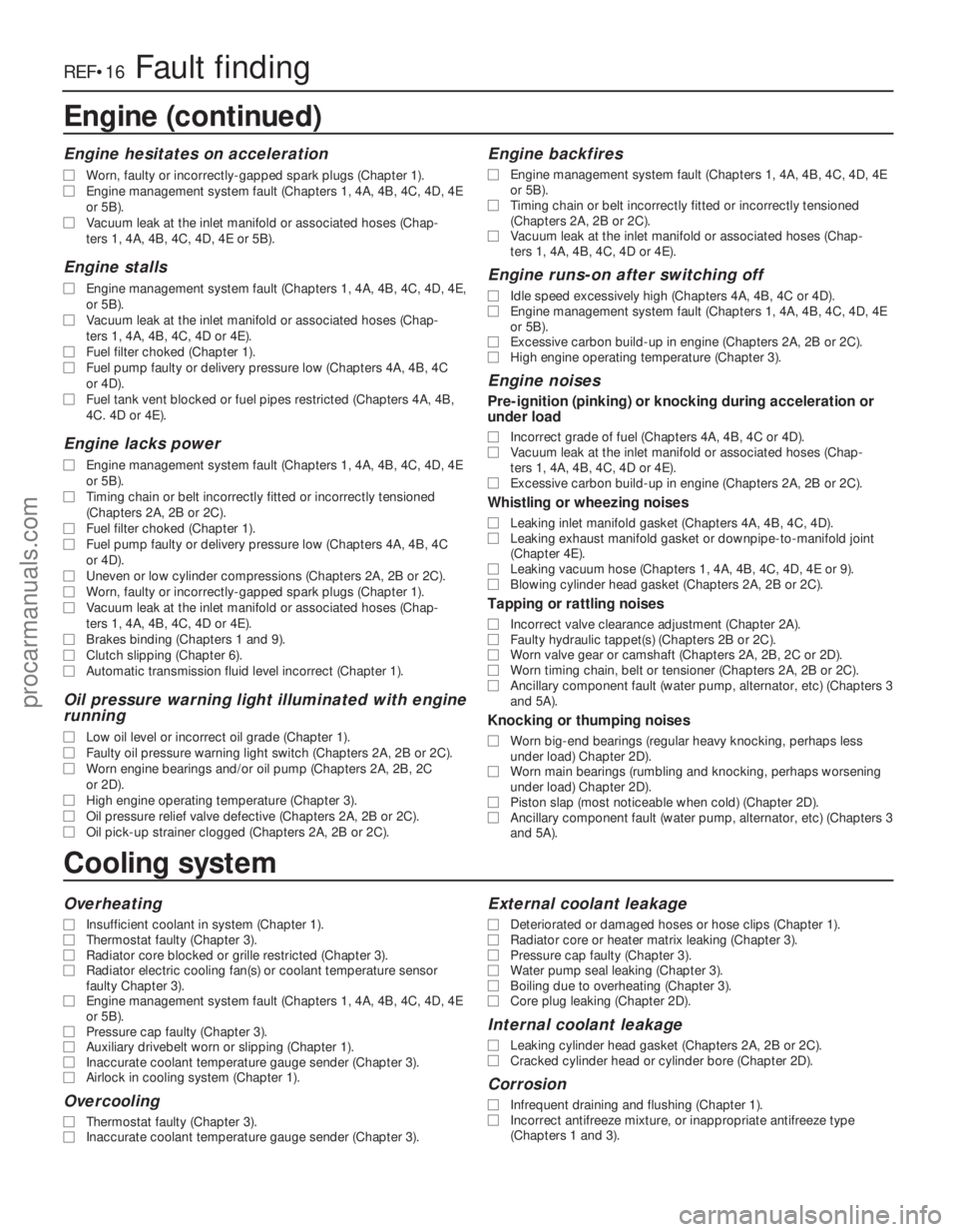
REF•16Fault finding
Cooling system
Overheating
m
mInsufficient coolant in system (Chapter 1).
m
m Thermostat faulty (Chapter 3).
m
m Radiator core blocked or grille restricted (Chapter 3).
m
m Radiator electric cooling fan(s) or coolant temperature sensor
faulty Chapter 3).
m m Engine management system fault (Chapters 1, 4A, 4B, 4C, 4D, 4E
or 5B).
m m Pressure cap faulty (Chapter 3).
m
m Auxiliary drivebelt worn or slipping (Chapter 1).
m
m Inaccurate coolant temperature gauge sender (Chapter 3).
m
m Airlock in cooling system (Chapter 1).
Overcooling
m
mThermostat faulty (Chapter 3).
m
m Inaccurate coolant temperature gauge sender (Chapter 3).
External coolant leakage
m
mDeteriorated or damaged hoses or hose clips (Chapter 1).
m
m Radiator core or heater matrix leaking (Chapter 3).
m
m Pressure cap faulty (Chapter 3).
m
m Water pump seal leaking (Chapter 3).
m
m Boiling due to overheating (Chapter 3).
m
m Core plug leaking (Chapter 2D).
Internal coolant leakage
m
mLeaking cylinder head gasket (Chapters 2A, 2B or 2C).
m
m Cracked cylinder head or cylinder bore (Chapter 2D).
Corrosion
m
mInfrequent draining and flushing (Chapter 1).
m
m Incorrect antifreeze mixture, or inappropriate antifreeze type
(Chapters 1 and 3).
Engine (continued)
Engine hesitates on acceleration
m
m Worn, faulty or incorrectly-gapped spark plugs (Chapter 1).
m
m Engine management system fault (Chapters 1, 4A, 4B, 4C, 4D, 4E
or 5B).
m m Vacuum leak at the inlet manifold or associated hoses (Chap-
ters 1, 4A, 4B, 4C, 4D, 4E or 5B).
Engine stalls
m mEngine management system fault (Chapters 1, 4A, 4B, 4C, 4D, 4E,
or 5B).
m m Vacuum leak at the inlet manifold or associated hoses (Chap-
ters 1, 4A, 4B, 4C, 4D or 4E).
m m Fuel filter choked (Chapter 1).
m
m Fuel pump faulty or delivery pressure low (Chapters 4A, 4B, 4C
or 4D).
m m Fuel tank vent blocked or fuel pipes restricted (Chapters 4A, 4B,
4C. 4D or 4E).
Engine lacks power
m mEngine management system fault (Chapters 1, 4A, 4B, 4C, 4D, 4E
or 5B).
m m Timing chain or belt incorrectly fitted or incorrectly tensioned
(Chapters 2A, 2B or 2C).
m m Fuel filter choked (Chapter 1).
m
m Fuel pump faulty or delivery pressure low (Chapters 4A, 4B, 4C
or 4D).
m m Uneven or low cylinder compressions (Chapters 2A, 2B or 2C).
m
m Worn, faulty or incorrectly-gapped spark plugs (Chapter 1).
m
m Vacuum leak at the inlet manifold or associated hoses (Chap-
ters 1, 4A, 4B, 4C, 4D or 4E).
m m Brakes binding (Chapters 1 and 9).
m
m Clutch slipping (Chapter 6).
m
m Automatic transmission fluid level incorrect (Chapter 1).
Oil pressure warning light illuminated with engine
running
m mLow oil level or incorrect oil grade (Chapter 1).
m
m Faulty oil pressure warning light switch (Chapters 2A, 2B or 2C).
m
m Worn engine bearings and/or oil pump (Chapters 2A, 2B, 2C
or 2D).
m m High engine operating temperature (Chapter 3).
m
m Oil pressure relief valve defective (Chapters 2A, 2B or 2C).
m
m Oil pick-up strainer clogged (Chapters 2A, 2B or 2C).
Engine backfires
m
mEngine management system fault (Chapters 1, 4A, 4B, 4C, 4D, 4E
or 5B).
m m Timing chain or belt incorrectly fitted or incorrectly tensioned
(Chapters 2A, 2B or 2C).
m m Vacuum leak at the inlet manifold or associated hoses (Chap-
ters 1, 4A, 4B, 4C, 4D or 4E).
Engine runs-on after switching off
m mIdle speed excessively high (Chapters 4A, 4B, 4C or 4D).
m
m Engine management system fault (Chapters 1, 4A, 4B, 4C, 4D, 4E
or 5B).
m m Excessive carbon build-up in engine (Chapters 2A, 2B or 2C).
m
m High engine operating temperature (Chapter 3).
Engine noises
Pre-ignition (pinking) or knocking during acceleration or
under load
m mIncorrect grade of fuel (Chapters 4A, 4B, 4C or 4D).
m
m Vacuum leak at the inlet manifold or associated hoses (Chap-
ters 1, 4A, 4B, 4C, 4D or 4E).
m m Excessive carbon build-up in engine (Chapters 2A, 2B or 2C).
Whistling or wheezing noises
m
mLeaking inlet manifold gasket (Chapters 4A, 4B, 4C, 4D).
m
m Leaking exhaust manifold gasket or downpipe-to-manifold joint
(Chapter 4E).
m m Leaking vacuum hose (Chapters 1, 4A, 4B, 4C, 4D, 4E or 9).
m
m Blowing cylinder head gasket (Chapters 2A, 2B or 2C).
Tapping or rattling noises
m
mIncorrect valve clearance adjustment (Chapter 2A).
m
m Faulty hydraulic tappet(s) (Chapters 2B or 2C).
m
m Worn valve gear or camshaft (Chapters 2A, 2B, 2C or 2D).
m
m Worn timing chain, belt or tensioner (Chapters 2A, 2B or 2C).
m
m Ancillary component fault (water pump, alternator, etc) (Chapters 3
and 5A).
Knocking or thumping noises
m mWorn big-end bearings (regular heavy knocking, perhaps less
under load) Chapter 2D).
m m Worn main bearings (rumbling and knocking, perhaps worsening
under load) Chapter 2D).
m m Piston slap (most noticeable when cold) (Chapter 2D).
m
m Ancillary component fault (water pump, alternator, etc) (Chapters 3
and 5A).
procarmanuals.com
http://vnx.su