gas tank size FORD FIESTA 1989 Service Repair Manual
[x] Cancel search | Manufacturer: FORD, Model Year: 1989, Model line: FIESTA, Model: FORD FIESTA 1989Pages: 296, PDF Size: 10.65 MB
Page 112 of 296

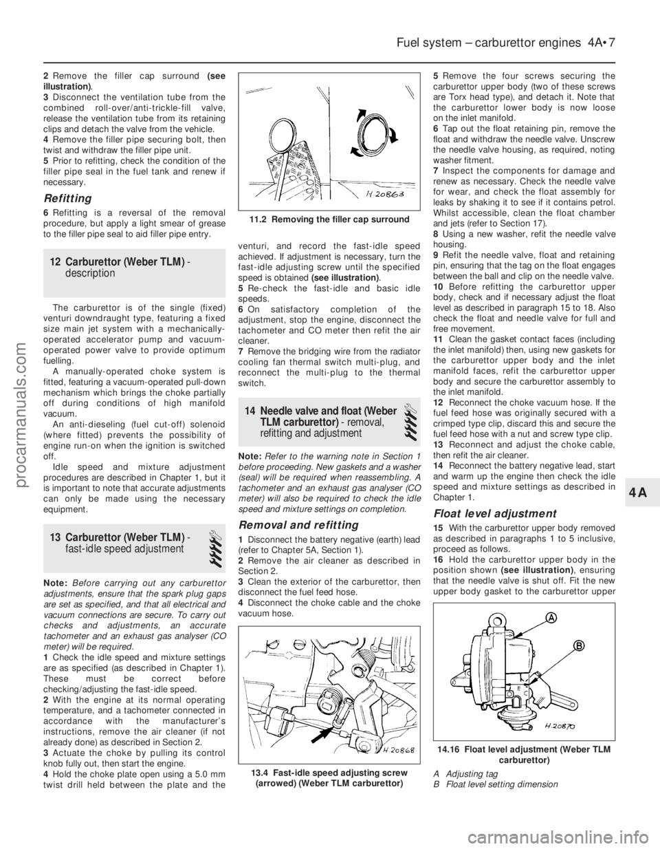
2Remove the filler cap surround (see
illustration) .
3 Disconnect the ventilation tube from the
combined roll-over/anti-trickle-fill valve,
release the ventilation tube from its retaining
clips and detach the valve from the vehicle.
4 Remove the filler pipe securing bolt, then
twist and withdraw the filler pipe unit.
5 Prior to refitting, check the condition of the
filler pipe seal in the fuel tank and renew if
necessary.
Refitting
6 Refitting is a reversal of the removal
procedure, but apply a light smear of grease
to the filler pipe seal to aid filler pipe entry.
12 Carburettor (Weber TLM) -
description
The carburettor is of the single (fixed)
venturi downdraught type, featuring a fixed
size main jet system with a mechanically-
operated accelerator pump and vacuum-
operated power valve to provide optimum
fuelling. A manually-operated choke system is
fitted, featuring a vacuum-operated pull-down
mechanism which brings the choke partially
off during conditions of high manifold
vacuum. An anti-dieseling (fuel cut-off) solenoid
(where fitted) prevents the possibility of
engine run-on when the ignition is switched
off. Idle speed and mixture adjustment
procedures are described in Chapter 1, but it
is important to note that accurate adjustments
can only be made using the necessary
equipment.
13 Carburettor (Weber TLM) -
fast-idle speed adjustment
4
Note: Before carrying out any carburettor
adjustments, ensure that the spark plug gaps
are set as specified, and that all electrical and
vacuum connections are secure. To carry out
checks and adjustments, an accurate
tachometer and an exhaust gas analyser (CO
meter) will be required.
1 Check the idle speed and mixture settings
are as specified (as described in Chapter 1).
These must be correct before
checking/adjusting the fast-idle speed.
2 With the engine at its normal operating
temperature, and a tachometer connected in
accordance with the manufacturer’s
instructions, remove the air cleaner (if not
already done) as described in Section 2.
3 Actuate the choke by pulling its control
knob fully out, then start the engine.
4 Hold the choke plate open using a 5.0 mm
twist drill held between the plate and the venturi, and record the fast-idle speed
achieved. If adjustment is necessary, turn the
fast-idle adjusting screw until the specified
speed is obtained
(see illustration).
5 Re-check the fast-idle and basic idle
speeds.
6 On satisfactory completion of the
adjustment, stop the engine, disconnect the
tachometer and CO meter then refit the air
cleaner.
7 Remove the bridging wire from the radiator
cooling fan thermal switch multi-plug, and
reconnect the multi-plug to the thermal
switch.
14 Needle valve and float (Weber
TLM carburettor) - removal,
refitting and adjustment
4
Note: Refer to the warning note in Section 1
before proceeding. New gaskets and a washer
(seal) will be required when reassembling. A
tachometer and an exhaust gas analyser (CO
meter) will also be required to check the idle
speed and mixture settings on completion.
Removal and refitting
1 Disconnect the battery negative (earth) lead
(refer to Chapter 5A, Section 1).
2 Remove the air cleaner as described in
Section 2.
3 Clean the exterior of the carburettor, then
disconnect the fuel feed hose.
4 Disconnect the choke cable and the choke
vacuum hose. 5
Remove the four screws securing the
carburettor upper body (two of these screws
are Torx head type), and detach it. Note that
the carburettor lower body is now loose
on the inlet manifold.
6 Tap out the float retaining pin, remove the
float and withdraw the needle valve. Unscrew
the needle valve housing, as required, noting
washer fitment.
7 Inspect the components for damage and
renew as necessary. Check the needle valve
for wear, and check the float assembly for
leaks by shaking it to see if it contains petrol.
Whilst accessible, clean the float chamber
and jets (refer to Section 17).
8 Using a new washer, refit the needle valve
housing.
9 Refit the needle valve, float and retaining
pin, ensuring that the tag on the float engages
between the ball and clip on the needle valve.
10 Before refitting the carburettor upper
body, check and if necessary adjust the float
level as described in paragraph 15 to 18. Also
check the float and needle valve for full and
free movement.
11 Clean the gasket contact faces (including
the inlet manifold) then, using new gaskets for
the carburettor upper body and the inlet
manifold faces, refit the carburettor upper
body and secure the carburettor assembly to
the inlet manifold.
12 Reconnect the choke vacuum hose. If the
fuel feed hose was originally secured with a
crimped type clip, discard this and secure the
fuel feed hose with a nut and screw type clip.
13 Reconnect and adjust the choke cable,
then refit the air cleaner.
14 Reconnect the battery negative lead, start
and warm up the engine then check the idle
speed and mixture settings as described in
Chapter 1.
Float level adjustment
15 With the carburettor upper body removed
as described in paragraphs 1 to 5 inclusive,
proceed as follows.
16 Hold the carburettor upper body in the
position shown (see illustration) , ensuring
that the needle valve is shut off. Fit the new
upper body gasket to the carburettor upper
Fuel system – carburettor engines 4A•7
13.4 Fast-idle speed adjusting screw (arrowed) (Weber TLM carburettor)
11.2 Removing the filler cap surround
14.16 Float level adjustment (Weber TLM carburettor)
A Adjusting tag
B Float level setting dimension
4A
1595Ford Fiesta Remakeprocarmanuals.com
http://vnx.su
Page 279 of 296

1595 Ford Fiesta Remake
MOT test checksREF•13
REF
MExamine the handbrake mechanism,
checking for frayed or broken cables,
excessive corrosion, or wear or insecurity of
the linkage. Check that the mechanism works
on each relevant wheel, and releases fully,
without binding.
M It is not possible to test brake efficiency
without special equipment, but a road test can
be carried out later to check that the vehicle
pulls up in a straight line.
Fuel and exhaust systems
M Inspect the fuel tank (including the filler
cap), fuel pipes, hoses and unions. All
components must be secure and free fr om
leaks.
M Examine the exhaust system over its entire
length, checking for any damaged, broken or
missing mountings, security of the retaining
clamps and rust or corrosion.
Wheels and tyres
M Examine the sidewalls and tread area of
each tyre in turn. Check for cuts, tears, lumps,
bulges, separation of the tread, and exposure
of the ply or cord due to wear or damage.
Check that the tyre bead is correctly seated
on the wheel rim, that the valve is sound and pr
operly seated, and that the wheel is not
distorted or damaged.
M Check that the tyres are of the correct size
for the vehicle, that they are of the same size
and type on each axle, and that the pressur es
ar e correct.
M Check the tyre tread depth. The legal
minimum at the time of writing is 1.6 mm over
at least three-quarters of the tread width.
Abnormal tread wear may indicate incorrect
fr ont wheel alignment.
Body corrosion
M Check the condition of the entire vehicle
structur e for signs of corrosion in load-bearing
ar eas. (These include chassis box sections,
side sills, cross-members, pillars, and all
suspension, steering, braking system and
seat belt mountings and anchorages.) Any
corrosion which has seriously reduced the
thickness of a load-bearing area is likely to
cause the vehicle to fail. In this case
pr ofessional repairs are likely to be needed.
M Damage or corrosion which causes sharp
or otherwise dangerous edges to be exposed
will also cause the vehicle to fail.
Petrol models
M Have the engine at normal operating
temperatur e, and make sure that it is in good
tune (ignition system in good order, air filter
element clean, etc).
M Befor e any measurements are carried out,
raise the engine speed to around 2500 rpm,
and hold it at this speed for 20 seconds. Allow the engine speed to return to idle, and watch
for smoke emissions from the exhaust
tailpipe. If the idle speed is obviously much
too high, or if dense blue or clearly-visible
black smoke comes from the tailpipe for more
than 5 seconds, the vehicle will fail. As a rule
of thumb, blue smoke signifies oil being burnt
(engine wear) while black smoke signifies
unbur nt fuel (dirty air cleaner element, or other
carbur ettor or fuel system fault).
M An exhaust gas analyser capable of
measuring carbon monoxide (CO) and
hydr ocarbons (HC) is now needed. If such an
instrument cannot be hired or borrowed, a
local garage may agree to perform the check
for a small fee.
CO emissions (mixture)
M At the time of writing, the maximum CO
level at idle is 3.5% for vehicles first used after
August 1986 and 4.5% for older vehicles.
Fr om January 1996 a much tighter limit
(ar ound 0.5%) applies to catalyst-equipped
vehicles first used from August 1992. If the
CO level cannot be reduced far enough to
pass the test (and the fuel and ignition
systems are otherwise in good condition) then
the carburettor is badly worn, or there is some
pr oblem in the fuel injection system or
catalytic converter (as applicable).
HC emissionsM With the CO emissions within limits, HC
emissions must be no more than 1200 ppm
(parts per million). If the vehicle fails this test
at idle, it can be re-tested at around 2000 rpm;
if the HC level is then 1200 ppm or less, this
counts as a pass.
M Excessive HC emissions can be caused by
oil being burnt, but they are more likely to be
due to unburnt fuel.
Diesel models
M The only emission test applicable to Diesel
engines is the measuring of exhaust smoke
density . The test involves accelerating the
engine several times to its maximum
unloaded speed.
Note: It is of the utmost importance that the
engine timing belt is in good condition before
the test is carried out.
M
Excessive smoke can be caused by a dirty
air cleaner element. Otherwise, professional
advice may be needed to find the cause.
4Checks carried out on
YOUR VEHICLE’S EXHAUST
EMISSION SYSTEM
procarmanuals.com
http://vnx.su