instrument cluster FORD FIESTA 1989 Service Repair Manual
[x] Cancel search | Manufacturer: FORD, Model Year: 1989, Model line: FIESTA, Model: FORD FIESTA 1989Pages: 296, PDF Size: 10.65 MB
Page 231 of 296
31Remove the seat belt upper anchor bolt
cover and undo the bolt.
32 Carefully prise up the seat belt guide from
its trim panel location, and remove it from the
seat belt. Allow the seat belt to retract through
the trim panel, clamping a clothes peg, or
similar item, onto its end to prevent it being
fully wound into the retractor.
33 Manoeuvre the trim panel out from under
the scuff plate, slackening or removing the
rearward scuff plate retaining screws if
necessary.
Refitting
34 Engage the trim panel under the scuff
plate, and refit and tighten the scuff plate
retaining screws as necessary.
35 Pull the seat belt through the trim panel,
refit the guide and press the panel onto the
body to re-engage the trim clips.
36 Refit the upper seat belt anchor,
tightening the bolt to the specified torque, and
refit its cover. Ensure that the anchor is free to
rotate.
37 Refit the plastic stud and the screw to the
lower and upper rear corners of the trim,
respectively.
38 Refit the seat belt to the slide bar, then
refit the slide bar by reversing the method of
removal. Ensure that the seat belt is not
twisted as it is located on the slide bar, and
that the bolt is tightened to the specified
torque.
39 Refit the rear seat cushion by reversing
the method of removal.
40 Press the door aperture weatherstrip back
into position.
Load compartment trim panels
(Courier models)
Removal
41 Using either a trim clip releasing tool or a
screwdriver with a broad flat blade, and
protecting the paintwork and trim with a layer
of rag, extract the clips securing the panel and
withdraw it.
Refitting
42 Refitting is the reverse of the removal
procedure.
43 Parcel shelf support/
loudspeaker housing -
removal and refitting
3
Removal
1 Remove the rear seat belt and retractor unit
from the appropriate side of the vehicle, as
described in Section 41.
2 Disconnect the luggage compartment
(courtesy) light, where fitted, by prising the
light assembly from its location using a thin
flat-bladed screwdriver, then twist the
bulbholder anti-clockwise to remove.
3 Detach the loudspeaker, where fitted, by
removing its retaining screws, disengaging its
locating tags and disconnecting its multi-plug. 4
Fold the seat backrest forward. Remove the
parcel shelf support/rear loudspeaker housing
retaining screws, then manoeuvre it out from
under the quarter panel trim as necessary, to
clear the seat backrest catch striker pin.
Refitting
5 Refitting is a reversal of the removal
procedure.
44 Passenger grab handle -
removal and refitting
1
Removal
1 Carefully prise up the trim flaps on either
end of the handle to expose the two mounting
screws.
2 Undo the mounting screws and remove the
grab handle.
Refitting
3 Refitting is the reverse procedure to
removal.
45 Centre console -
removal and refitting
1
Removal
1 Disconnect the battery negative (earth) lead
(refer to Chapter 5A, Section 1).
2 Carefully prise up the console switches, as
necessary, using a flat-bladed screwdriver,
then disconnect their multi-plugs.
3 Unscrew the gear lever knob, then raise the
gaiter from its location and lift it off over the
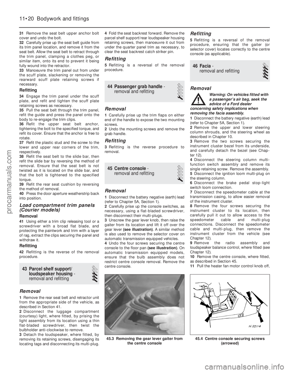
gear lever (see illustration) . A similar method
is also used to remove the selector cover on
automatic transmission equipped vehicles.
4 Undo the four screws securing the centre
console to the floor pan (see illustration). On
automatic transmission equipped models,
ensure that the bulb assembly does not
restrict centre console removal. Remove the
centre console.
Refitting
5 Refitting is a reversal of the removal
procedure, ensuring that the gaiter (or
selector cover) locates correctly to the centre
console (as applicable).
46 Facia - removal and refitting
4
Removal
Warning: On vehicles fitted with
a passenger’s air bag, seek the
advice of a Ford dealer
concerning safety implications when
removing the facia assembly.
1 Disconnect the battery negative (earth) lead
(refer to Chapter 5A, Section 1).
2 Remove the upper and lower steering
column shrouds, and the steering wheel as
described in Chapter 10.
3 Remove the two screws securing the
instrument cluster bezel from its underside,
and carefully detach the bezel (see Chap-
ter 12).
4 Disconnect the steering column multi-
function switch assembly and remove its
single retaining screw. Remove the assembly.
5 Disconnect the ignition loom multi-plug on
the steering column.
6 Disconnect the brake pedal stop-light
switch loom connection.
7 Disconnect the speedometer cable at the
transmission casing, to allow easier removal
of the instrument cluster.
8 Remove the four screws securing the
instrument cluster to its location, then
carefully pull it out to allow access to the
speedometer cable and multi-plug
connections. Disconnect the speedometer
cable and multi-plug, then remove the
instrument cluster from the vehicle (see
Chapter 12).
9 Remove the radio assembly and
loudspeaker balance control, where fitted (see
Chapter 12).
10 Remove the centre console, where fitted,
as described in Section 45.
11 Pull the heater fan motor control knob off,
11•20 Bodywork and fittings
45.4 Centre console securing screws
(arrowed)45.3 Removing the gear lever gaiter fromthe centre console
1595Ford Fiesta Remakeprocarmanuals.com
http://vnx.su
Page 232 of 296
then move the air distribution and
temperature controls fully to the right. Unclip
and remove the heater slide facia towards the
left-hand side of the vehicle, removing the
slide control knobs only as necessary, and
disconnecting its bulbholder (bayonet type) as
it is withdrawn.
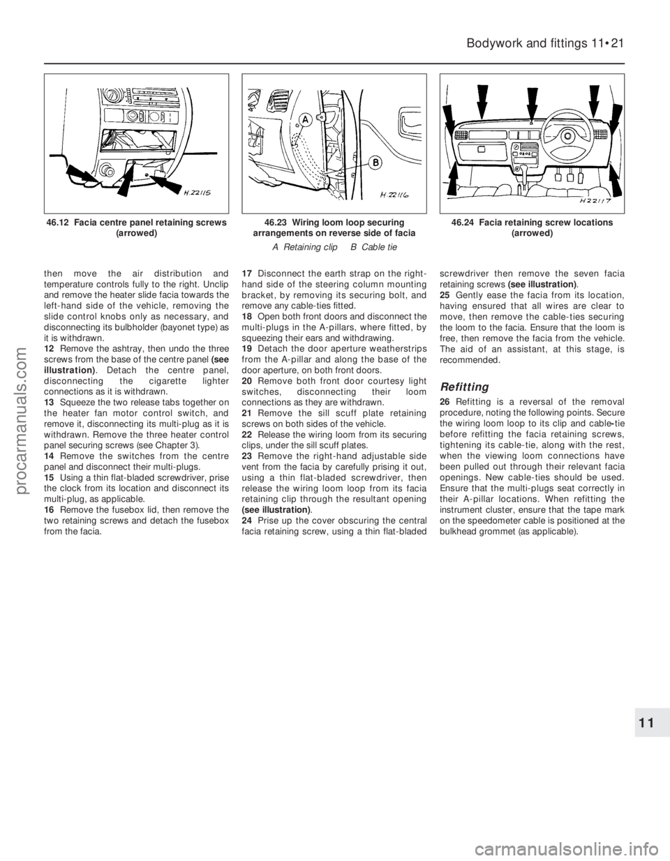
12Remove the ashtray, then undo the three
screws from the base of the centre panel (see
illustration) . Detach the centre panel,
disconnecting the cigarette lighter
connections as it is withdrawn.
13 Squeeze the two release tabs together on
the heater fan motor control switch, and
remove it, disconnecting its multi-plug as it is
withdrawn. Remove the three heater control
panel securing screws (see Chapter 3).
14 Remove the switches from the centre
panel and disconnect their multi-plugs.
15 Using a thin flat-bladed screwdriver, prise
the clock from its location and disconnect its
multi-plug, as applicable.
16 Remove the fusebox lid, then remove the
two retaining screws and detach the fusebox
from the facia. 17
Disconnect the earth strap on the right-
hand side of the steering column mounting
bracket, by removing its securing bolt, and
remove any cable-ties fitted.
18 Open both front doors and disconnect the
multi-plugs in the A-pillars, where fitted, by
squeezing their ears and withdrawing.
19 Detach the door aperture weatherstrips
from the A-pillar and along the base of the
door aperture, on both front doors.
20 Remove both front door courtesy light
switches, disconnecting their loom
connections as they are withdrawn.
21 Remove the sill scuff plate retaining
screws on both sides of the vehicle.
22 Release the wiring loom from its securing
clips, under the sill scuff plates.
23 Remove the right-hand adjustable side
vent from the facia by carefully prising it out,
using a thin flat-bladed screwdriver, then
release the wiring loom loop from its facia
retaining clip through the resultant opening
(see illustration) .
24 Prise up the cover obscuring the central
facia retaining screw, using a thin flat-bladed screwdriver then remove the seven facia
retaining screws
(see illustration) .
25 Gently ease the facia from its location,
having ensured that all wires are clear to
move, then remove the cable-ties securing
the loom to the facia. Ensure that the loom is
free, then remove the facia from the vehicle.
The aid of an assistant, at this stage, is
recommended.
Refitting
26 Refitting is a reversal of the removal
procedure, noting the following points. Secure
the wiring loom loop to its clip and cable -tie
before refitting the facia retaining screws,
tightening its cable-tie, along with the rest,
when the viewing loom connections have
been pulled out through their relevant facia
openings. New cable-ties should be used.
Ensure that the multi-plugs seat correctly in
their A-pillar locations. When refitting the
instrument cluster, ensure that the tape mark
on the speedometer cable is positioned at the
bulkhead grommet (as applicable).
Bodywork and fittings 11•21
46.24 Facia retaining screw locations (arrowed)46.23 Wiring loom loop securing
arrangements on reverse side of facia
A Retaining clip B Cable tie46.12 Facia centre panel retaining screws (arrowed)
11
1595Ford Fiesta Remakeprocarmanuals.com
http://vnx.su
Page 241 of 296
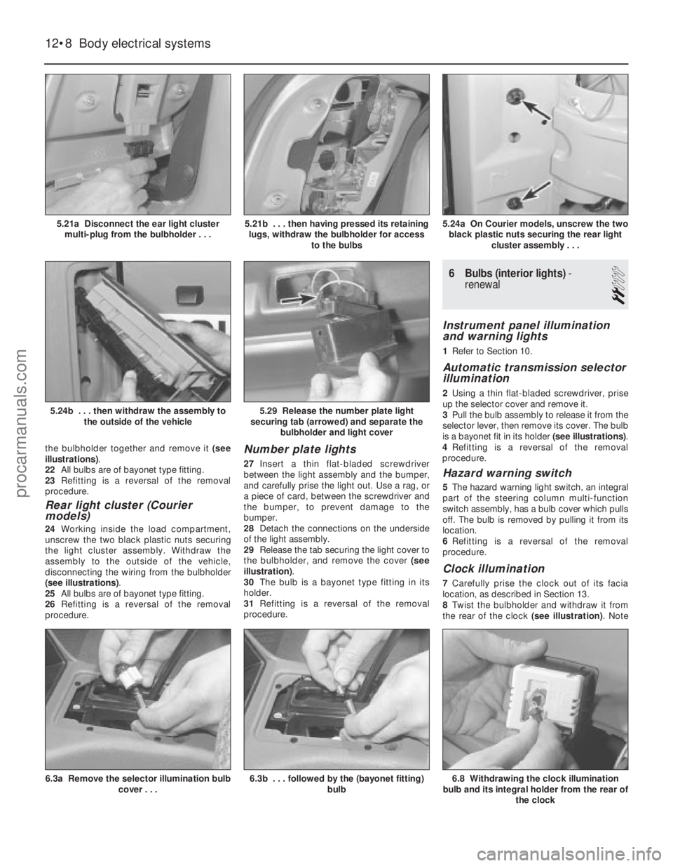
the bulbholder together and remove it (see
illustrations) .
22 All bulbs are of bayonet type fitting.
23 Refitting is a reversal of the removal
procedure.
Rear light cluster (Courier
models)
24 Working inside the load compartment,
unscrew the two black plastic nuts securing
the light cluster assembly. Withdraw the
assembly to the outside of the vehicle,
disconnecting the wiring from the bulbholder
(see illustrations) .
25 All bulbs are of bayonet type fitting.
26 Refitting is a reversal of the removal
procedure.
Number plate lights
27 Insert a thin flat-bladed screwdriver
between the light assembly and the bumper,
and carefully prise the light out. Use a rag, or
a piece of card, between the screwdriver and
the bumper, to prevent damage to the
bumper.
28 Detach the connections on the underside
of the light assembly.
29 Release the tab securing the light cover to
the bulbholder, and remove the cover (see
illustration) .
30 The bulb is a bayonet type fitting in its
holder.
31 Refitting is a reversal of the removal
procedure.
6 Bulbs (interior lights) -
renewal
2
Instrument panel illumination
and warning lights
1 Refer to Section 10.
Automatic transmission selector
illumination
2Using a thin flat-bladed screwdriver, prise
up the selector cover and remove it.
3 Pull the bulb assembly to release it from the
selector lever, then remove its cover. The bulb
is a bayonet fit in its holder (see illustrations).
4 Refitting is a reversal of the removal
procedure.
Hazard warning switch
5 The hazard warning light switch, an integral
part of the steering column multi-function
switch assembly, has a bulb cover which pulls
off. The bulb is removed by pulling it from its
location.
6 Refitting is a reversal of the removal
procedure.
Clock illumination
7 Carefully prise the clock out of its facia
location, as described in Section 13.
8 Twist the bulbholder and withdraw it from
the rear of the clock (see illustration). Note
12•8Body electrical systems
6.8 Withdrawing the clock illumination
bulb and its integral holder from the rear of
the clock6.3b . . . followed by the (bayonet fitting) bulb6.3a Remove the selector illumination bulbcover . . .
5.29 Release the number plate light
securing tab (arrowed) and separate the bulbholder and light cover5.24b . . . then withdraw the assembly to
the outside of the vehicle
5.24a On Courier models, unscrew the twoblack plastic nuts securing the rear light cluster assembly . . .5.21b . . . then having pressed its retaininglugs, withdraw the bulbholder for access to the bulbs5.21a Disconnect the ear light clustermulti-plug from the bulbholder . . .
1595Ford Fiesta Remakeprocarmanuals.com
http://vnx.su
Page 244 of 296
work should therefore be carried out by a
Ford dealer or service station with the
necessary facilities.
2Temporary adjustment can be made when
the headlight has been removed and refitted,
or to compensate for normal adjustment
whenever a heavy load is being carried. Turn
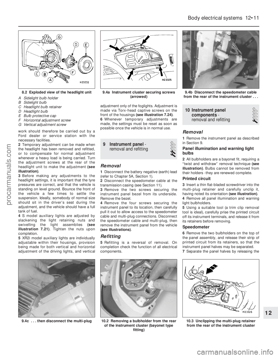
the adjustment screws at the rear of the
headlight unit to make the adjustment (see
illustration) .
3 Before making any adjustments to the
headlight settings, it is important that the tyre
pressures are correct, and that the vehicle is
standing on level ground. Bounce the front of
the vehicle a few times to settle the
suspension. Ideally, somebody of normal size
should sit in the driver’s seat during the
adjustment, and the vehicle should have a full
tank of fuel.
4 S model auxiliary lights are adjusted by
slackening the light retaining nuts and
swivelling the light assemblies (see
illustration 7.21) . Tighten the nuts upon
completion.
5 XR2i model auxiliary lights are individually
adjustable within their housings, provision
being made for both vertical and horizontal
adjustment of the driving lights, and vertical adjustment only of the foglights. Adjustment is
made via Torx-head captive screws on the
front of the housings
(see illustration 7.24) .
6 Whenever temporary adjustments are
made, the settings must be reset as soon as
possible once the vehicle is in normal use.
9 Instrument panel -
removal and refitting
2
Removal
1 Disconnect the battery negative (earth) lead
(refer to Chapter 5A, Section 1).
2 Disconnect the speedometer cable at the
transmission casing (see Section 11).
3 Remove the two screws securing the
instrument panel bezel from its underside.
Remove the bezel.
4 Remove the four screws securing the
instrument panel to its location, then carefully
pull it out to allow access to the speedometer
cable and multi-plug connections. Disconnect
the speedometer cable and multi-plug, then
remove the instrument panel from the vehicle
(see illustrations) .
Refitting
5Refitting is a reversal of removal. On
completion check the function of all electrical
components.
10 Instrument panel
components -
removal and refitting
1
Removal
1 Remove the instrument panel as described
in Section 9.
Panel illumination and warning light
bulbs
2 All bulbholders are a bayonet fit, requiring a
“twist and withdraw” removal technique (see
illustration) . Bulbs cannot be removed from
their holders -they are renewed complete.
Printed circuit
3 Insert a thin flat-bladed screwdriver into the
multi-plug retainer and carefully unclip it,
having noted its orientation (see illustration).
4 Remove all panel illumination and warning
light bulbholders.
5 Using a suitable tool (a trim clip removal
tool is ideal), carefully prise the printed circuit
off its instrument terminals, and release it from
its retainers before removing.
Speedometer
6 Remove the two bulbholders on the top of
the panel assembly, and release their strip of
printed circuit from its retainers, so that the
instrument panel halves may be separated.
7 Separate the panel halves by releasing the
Body electrical systems 12•11
9.4b Disconnect the speedometer cable
from the rear of the instrument cluster . . .9.4a Instrument cluster securing screws (arrowed)8.2 Exploded view of the headlight unit
A Sidelight bulb holder
B Sidelight bulb
C Headlight bulb retainer
D Headlight bulb
E Bulb protective cap
F Horizontal adjustment screw
G Vertical adjustment screw
10.3 Unclipping the multi-plug retainer from the rear of the instrument cluster10.2 Removing a bulbholder from the rear of the instrument cluster (bayonet type
fitting)9.4c . . . then disconnect the multi-plug
12
1595Ford Fiesta Remakeprocarmanuals.com
http://vnx.su
Page 245 of 296
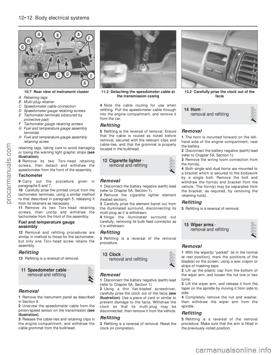
retaining tags, taking care to avoid damaging
or losing the warning light graphic strips (see
illustration) .
8 Remove its two Torx-head retaining
screws, then detach and withdraw the
speedometer from the front of the assembly.
Tachometer
9 Carry out the procedure given in
paragraphs 6 and 7.
10 Carefully prise the printed circuit from the
tachometer terminals, using a similar method
to that described in paragraph 5, releasing it
from its retainers as necessary.
11 Remove its two Torx-head retaining
screws, then unclip and withdraw the
tachometer from the front of the assembly.
Fuel and temperature gauge
assembly
12 Removal and refitting procedures are
similar in method to those for the tachometer,
but only one Torx-head screw retains the
assembly.
Refitting
13 Refitting is a reversal of removal.
11 Speedometer cable -
removal and refitting
2
Removal
1 Remove the instrument panel as described
in Section 9.
2 Unscrew the speedometer cable from the
pinion/speed sensor on the transmission (see
illustration) .
3 Release the cable-ties and retaining clips in
the engine compartment, and withdraw the
cable grommet from the bulkhead. 4
Note the cable routing for use when
refitting. Pull the speedometer cable through
into the engine compartment, and remove it
from the car.
Refitting
5 Refitting is the reversal of removal. Ensure
that the cable is routed as noted before
removal, secured with the relevant clips and
cable-ties, and that the grommet is properly
located in the bulkhead.
12 Cigarette lighter -
removal and refitting
1
Removal
1 Disconnect the battery negative (earth) lead
(refer to Chapter 5A, Section 1).
2 Remove the cigarette lighter element
(heated section).
3 Carefully prise the element barrel out from
the illuminated surround, disconnecting its
multi-plug as it is withdrawn.
4 Hinge the illuminated surround out
carefully, removing its bulb feed connector as
it is withdrawn.
Refitting
5 Refitting is a reversal of the removal
procedure.
13 Clock -
removal and refitting
1
Removal
1 Disconnect the battery negative (earth) lead
(refer to Chapter 5A, Section 1).
2 Using a thin flat-bladed screwdriver,
carefully prise the clock out of the facia (see
illustration) . Use a piece of card or similar to
prevent damage to the facia. Withdraw the
clock so that its multi-plug may be
disconnected, then remove it from the vehicle.
Refitting
3 Refitting is a reversal of removal. Reset the
clock on completion.
14 Horn -
removal and refitting
1
Removal
1 The horn is mounted forward on the left-
hand side of the engine compartment, near
the battery.
2 Disconnect the battery negative (earth) lead
(refer to Chapter 5A, Section 1).
3 Remove the wiring loom connection from
the horn(s).
4 Both single and dual horns are mounted to
a bracket which is secured to the bodywork
by a single bolt. Remove the bolt and
withdraw the horn(s) and bracket from the
vehicle. The horn(s) may be separated from
the bracket, as required, by removing the
retaining nut(s).
Refitting
5 Refitting is a reversal of removal.
15 Wiper arms -
removal and refitting
1
Removal
1 With the wiper(s) “parked” (ie in the normal
at-rest position), mark the positions of the
blade(s) on the screen, using a wax crayon or
strips of masking tape.
2 Lift up the plastic cap from the bottom of
the wiper arm, and loosen the nut one or two
turns.
3 Lift the wiper arm, and release it from the
taper on the spindle by moving it from side to
side.
4 Completely remove the nut and washer,
then withdraw the wiper arm from the
spindle.
Refitting
5 Refitting is a reversal of the removal
procedure. Make sure that the arm is fitted in
the previously-noted position.
12•12 Body electrical systems
13.2 Carefully prise the clock out of the facia11.2 Detaching the speedometer cable atthe transmission casing10.7 Rear view of instrument cluster
A Retaining tags
B Multi-plug retainer
C Speedometer cable connection
D Speedometer gauge retaining screws
E Tachometer terminals (obscured by protective pad)
F Tachometer gauge retaining screws
G Fuel and temperature gauge assembly
terminals
H Fuel and temperature gauge assembly retaining screw
1595Ford Fiesta Remakeprocarmanuals.com
http://vnx.su
Page 277 of 296
1595 Ford Fiesta Remake
MOT test checksREF•11
REF
Seat belts and seats
Note: The following checks are applicable to
all seat belts, front and rear.
M Examine the webbing of all the belts
(including rear belts if fitted) for cuts, serious
fraying or deterioration. Fasten and unfasten
each belt to check the buckles. If applicable,
check the retracting mechanism. Check the
security of all seat belt mountings accessible
fr om inside the vehicle.
M The front seats themselves must be
secur ely attached and the backrests must
lock in the upright position.
Doors
M Both front doors must be able to be opened
and closed from outside and inside, and must
latch securely when closed.
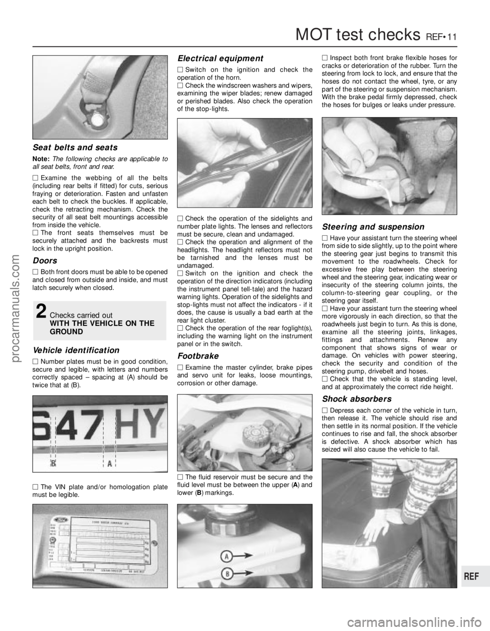
V ehicle identification
M Number plates must be in good condition,
secur e and legible, with letters and numbers
corr ectly spaced – spacing at (A) should be
twice that at (B).
M The VIN plate and/or homologation plate
must be legible.
Electrical equipment
M Switch on the ignition and check the
operation of the horn.
M Check the windscreen washers and wipers,
examining the wiper blades; renew damaged
or perished blades. Also check the operation
of the stop-lights.
M Check the operation of the sidelights and
number plate lights. The lenses and reflectors
must be secure, clean and undamaged.
M Check the operation and alignment of the
headlights. The headlight reflectors must not
be tarnished and the lenses must be
undamaged.
M Switch on the ignition and check the
operation of the direction indicators (including
the instrument panel tell-tale) and the hazard
war ning lights. Operation of the sidelights and
stop-lights must not affect the indicators - if it
does, the cause is usually a bad earth at the
r ear light cluster.
M Check the operation of the rear foglight(s),
including the warning light on the instrument
panel or in the switch.
Footbrake
M Examine the master cylinder, brake pipes
and servo unit for leaks, loose mountings,
corr osion or other damage.
M The fluid reservoir must be secure and the
fluid level must be between the upper ( A) and
lower ( B) markings. M
Inspect both front brake flexible hoses for
cracks or deterioration of the rubber . Turn the
steering from lock to lock, and ensure that the
hoses do not contact the wheel, tyre, or any
part of the steering or suspension mechanism.
With the brake pedal firmly depressed, check
the hoses for bulges or leaks under pressure.
Steering and suspension
M Have your assistant turn the steering wheel
fr om side to side slightly, up to the point where
the steering gear just begins to transmit this
movement to the roadwheels. Check for
excessive free play between the steering
wheel and the steering gear, indicating wear or
insecurity of the steering column joints, the
column-to-steering gear coupling, or the
steering gear itself.
M Have your assistant turn the steering wheel
mor e vigorously in each direction, so that the
r oadwheels just begin to turn. As this is done,
examine all the steering joints, linkages,
fittings and attachments. Renew any
component that shows signs of wear or
damage. On vehicles with power steering,
check the security and condition of the
steering pump, drivebelt and hoses.
M Check that the vehicle is standing level,
and at approximately the correct ride height.
Shock absorbers
M Depr ess each corner of the vehicle in turn,
then release it. The vehicle should rise and
then settle in its normal position. If the vehicle
continues to rise and fall, the shock absorber
is defective. A shock absorber which has
seized will also cause the vehicle to fail.
2Checks carried out
WITH THE VEHICLE ON THE
GROUND
procarmanuals.com
http://vnx.su