513 FORD FIESTA 2007 User Guide
[x] Cancel search | Manufacturer: FORD, Model Year: 2007, Model line: FIESTA, Model: FORD FIESTA 2007Pages: 1226, PDF Size: 61.26 MB
Page 692 of 1226
303-01 B-70 Engine - 2.OL Duratec-HE (M14) 303-01 B-70
IN-VEHICLE REPAIR
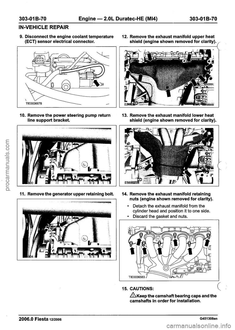
9. Disconnect the engine coolant temperature 12. Remove the exhaust manifold upper heat
(ECT) sensor electrical connector.
shield (engine shown removed for clarity).
('
10. Remove the power steering pump return 13. Remove the exhaust manifold lower heat
line support bracket.
shield (engine shown removed for clarity).
11. Remove the generator upper retaining bolt. 14. Remove the exhaust manifold retaining
nuts (engine shown removed for clarity).
Detach the exhaust manifold from the
cylinder head and position it to one side.
Discard the gasket and nuts.
15. CAUTIONS: c
n~ee~ the camshaft bearing caps and the
camshafts in order for installation.
2006.0 Fiesta 12/2006 G451308en
procarmanuals.com
Page 693 of 1226
303-01 B-71 Engine - 2.OL Duratec-HE (M14) 303-01 B-71
IN-VEHICLE REPAIR
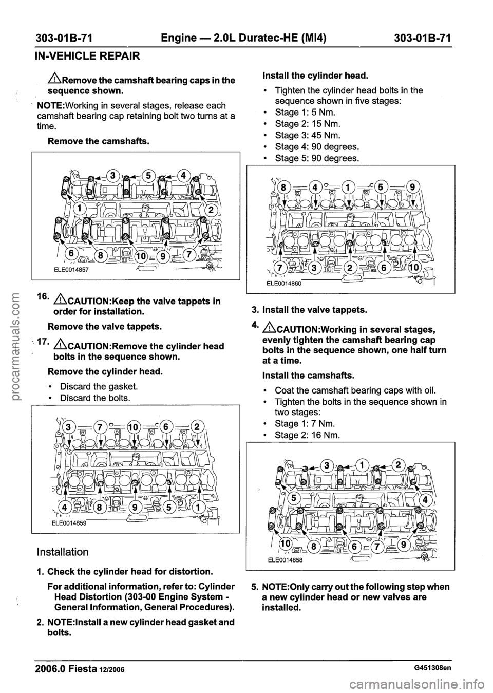
n~emove the camshaft bearing caps in the Install the
cylinder head.
i sequence shown. Tighten the cylinder head bolts in the
' N0TE:Working in several stages, release each sequence
shown in five stages:
camshaft bearing cap retaining bolt two turns at a Stage I : 5 Nm.
time. Stage 2: 15 Nm.
Remove the camshafts.
~CAUTION:K~~~ the valve tappets in
order for installation.
Remove the valve tappets.
( ' 17' &AUTION:R~~~~~ the cylinder head ' bolts in the sequence shown.
Remove the cylinder head.
Discard the gasket.
Discard the bolts.
Installation
Stage3:45Nm.
Stage 4: 90 degrees.
Stage 5: 90 degrees.
3. Install the valve tappets.
4m &AUTION:W~~~~~~ in several stages,
evenly tighten the camshaft bearing cap
bolts in the sequence shown, one half turn
at a time.
Install the camshafts.
Coat the camshaft bearing caps with oil.
Tighten the bolts in the sequence shown in
two stages:
Stage I: 7 Nm.
Stage 2: 16 Nm.
I i
I. Check the cylinder head for distortion. I I
For additional information, refer to: Cylinder 5. N0TE:Only carry out the following step when
Head Distortion
(303-00 Engine System - a new cylinder head or new valves are
General Information, General Procedures). installed.
2. N0TE:lnstall a new cylinder head gasket and
bolts.
2006.0 Fiesta 1212006 G451308en
procarmanuals.com
Page 694 of 1226
303-01 B-72 Engine - 2.OL Duratec-HE (M14) 303-01 B-72
IN-VEHICLE REPAIR
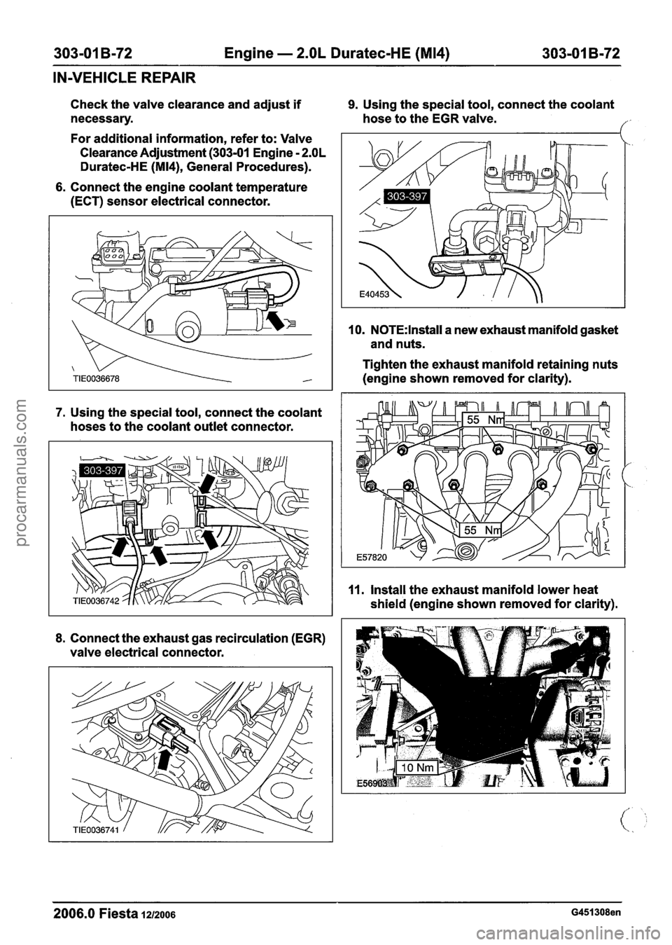
Check the valve clearance and adjust if 9. Using the special tool, connect the coolant
necessary. hose to the EGR valve.
/
For additional information, refer to: Valve
Clearance Adjustment
(303-01 Engine - 2.OL
Duratec-HE (M14), General Procedures).
6. Connect the engine coolant temperature
(ECT) sensor electrical connector.
7. Using the special tool, connect the coolant
hoses to the coolant outlet connector.
8. Connect the exhaust gas recirculation (EGR)
valve electrical connector. 10.
N0TE:lnstall a
new exhaust manifold gasket
and nuts.
Tighten the exhaust manifold retaining nuts
(engine shown removed for clarity).
11. Install the exhaust manifold lower heat
shield (engine shown removed for clarity).
2006.0 Fiesta 1212006 G451308en
procarmanuals.com
Page 695 of 1226
303-01 B-73 Engine - 2.OL Duratec-HE (M14) 303-01 B-73
IN-VEHICLE REPAIR
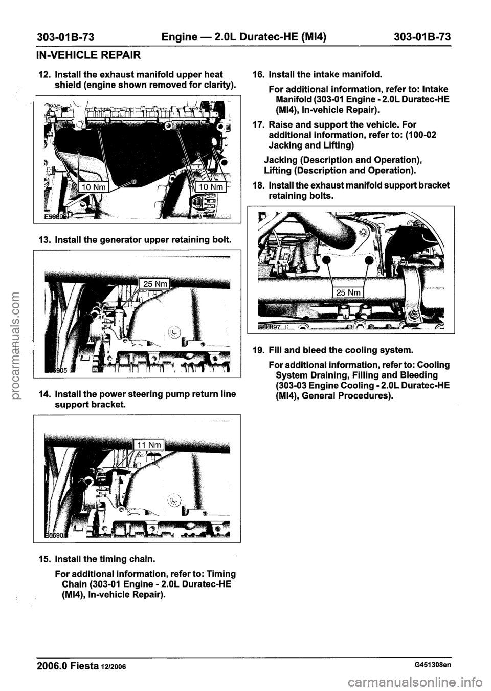
12. Install the exhaust manifold upper heat 16.
Install the intake manifold.
shield (engine shown removed for clarity).
For additional information, refer to: Intake
Manifold (303-01 Engine
- 2.OL Duratec-HE
(M14), ln-vehicle Repair).
17. Raise and support the vehicle. For
additional information, refer to: (1 00-02
Jacking and Lifting)
Jacking (Description and Operation),
Lifting (Description and Operation).
13. lnstall the generator upper retaining bolt.
18, lnstall the exhaust manifold support bracket
retaining bolts.
19. Fill and bleed the cooling system.
For additional information, refer to: Cooling
System Draining, Filling and Bleeding
(303-03 Engine Cooling
- 2.OL Duratec-HE
14. Install the power steering pump return line
(M14), General Procedures).
support bracket.
15. lnstall the timing chain.
For additional information, refer to: Timing
Chain (303-01 Engine
- 2.OL Duratec-HE
(M14), ln-vehicle Repair).
2006.0 Fiesta 12/2006 G451308en
procarmanuals.com
Page 705 of 1226
303-01 B-83 Engine - 2.OL Duratec-HE (M14) 303-01 B-83
DISASSEMBLY
Engine(21 134 8)
/ 1
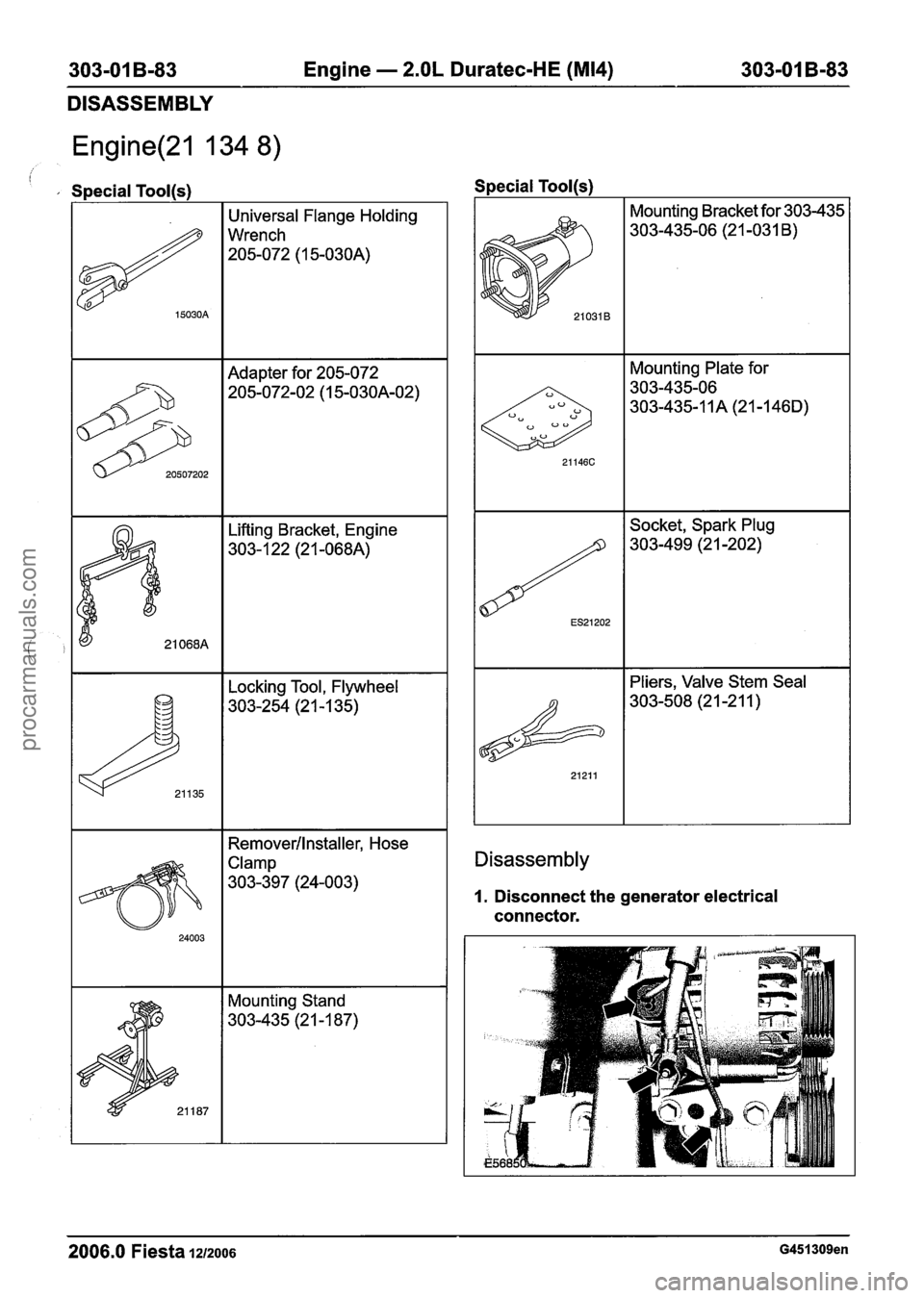
Special Tool(s)
Universal Flange Holding
Wrench
205-072 (1 5-030A)
Adapter for 205-072
205-072-02 (1 5-03OA-02)
Locking Tool, Flywheel
303-254 (2 1 -1 35)
Mounting Plate for
303-435-06
303-435-1
1A (21 -146D)
Socket, Spark Plug
303-499 (2 1 -202)
Pliers, Valve Stem Seal
303-508 (2 1-2 1 1 )
I I Removerllnstaller, Hose I Disassembly
1. Disconnect the generator electrical
connector.
Mounting Stand
303-435 (21 -1 87)
2006.0 Fiesta 1212006 G451309en
procarmanuals.com
Page 706 of 1226
303-01 B-84 Engine - 2.OL Duratec-HE (M14) 303-01 B-84
DISASSEMBLY
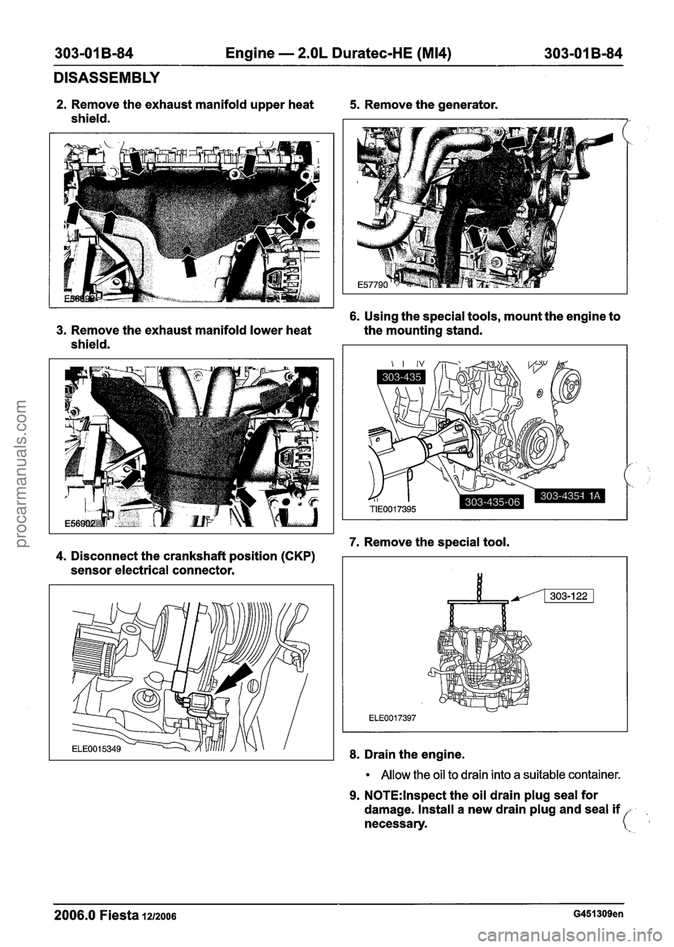
2. Remove the exhaust manifold upper heat 5. Remove the generator.
shield.
6. Using the special tools, mount the engine to
3. Remove the exhaust manifold lower heat the mounting stand.
shield.
7. Remove the special tool.
4. Disconnect the crankshaft position (CKP)
sensor electrical connector.
8. Drain the engine.
Allow the oil to drain into a suitable container.
9. N0TE:lnspect the oil drain plug seal for
damage. Install a new drain plug and seal
if
necessary.
2006.0 Fiesta 1212006 G451309en
procarmanuals.com
Page 707 of 1226
303-01 B-85 Engine - 2.OL Duratec-HE (M14) 303-01 B-85
DISASSEMBLY
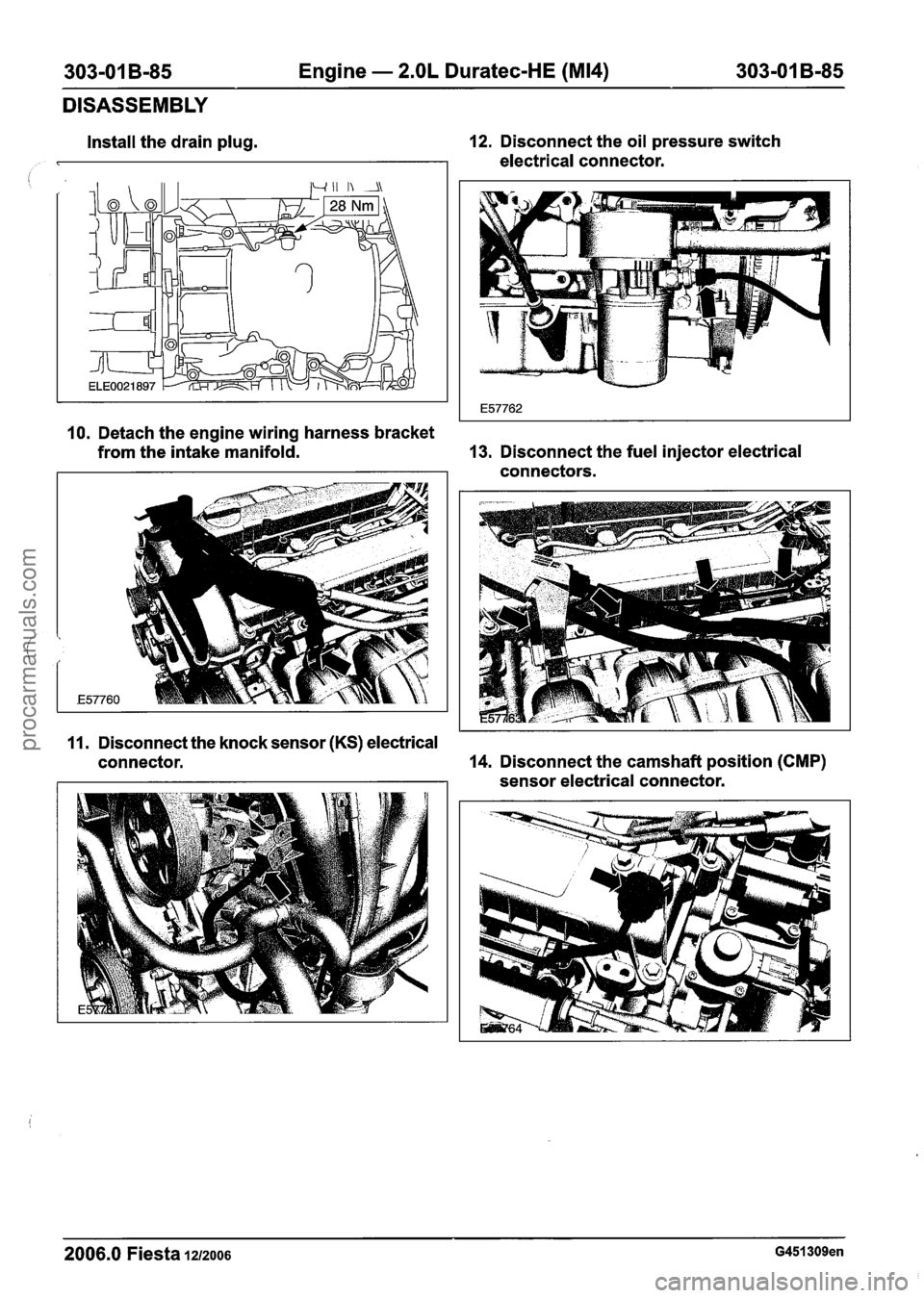
Install the drain plug. 12.
Disconnect the oil pressure switch
electrical connector.
10. Detach the engine wiring harness bracket
from the intake manifold. 13.
Disconnect the fuel injector electrical
connectors.
11. Disconnect the knock sensor
(KS) electrical
connector. 14.
Disconnect the camshaft position
(CMP)
sensor electrical connector.
2006.0 Fiesta 1212006 G451309en
procarmanuals.com
Page 708 of 1226
303-01 B-86 Engine - 2.OL Duratec-HE (M14) 303-01 B-86
DISASSEMBLY
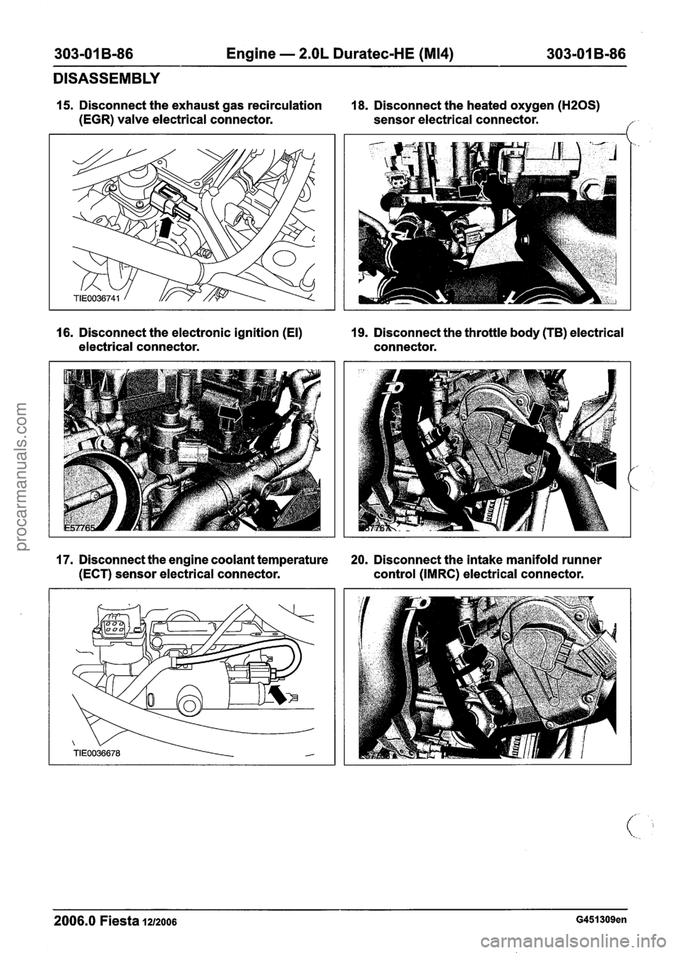
15. Disconnect the exhaust gas recirculation 18. Disconnect the heated oxygen (H20S)
(EGR) valve electrical connector. sensor electrical connector. f
16. Disconnect the electronic ignition (El) 19. Disconnect the throttle body (TB) electrical
electrical connector. connector.
17. Disconnect the engine coolant temperature 20. Disconnect the intake manifold runner
(ECT) sensor electrical connector. control (IMRC) electrical connector.
2006.0 Fiesta 1212006 G451309en
procarmanuals.com
Page 709 of 1226
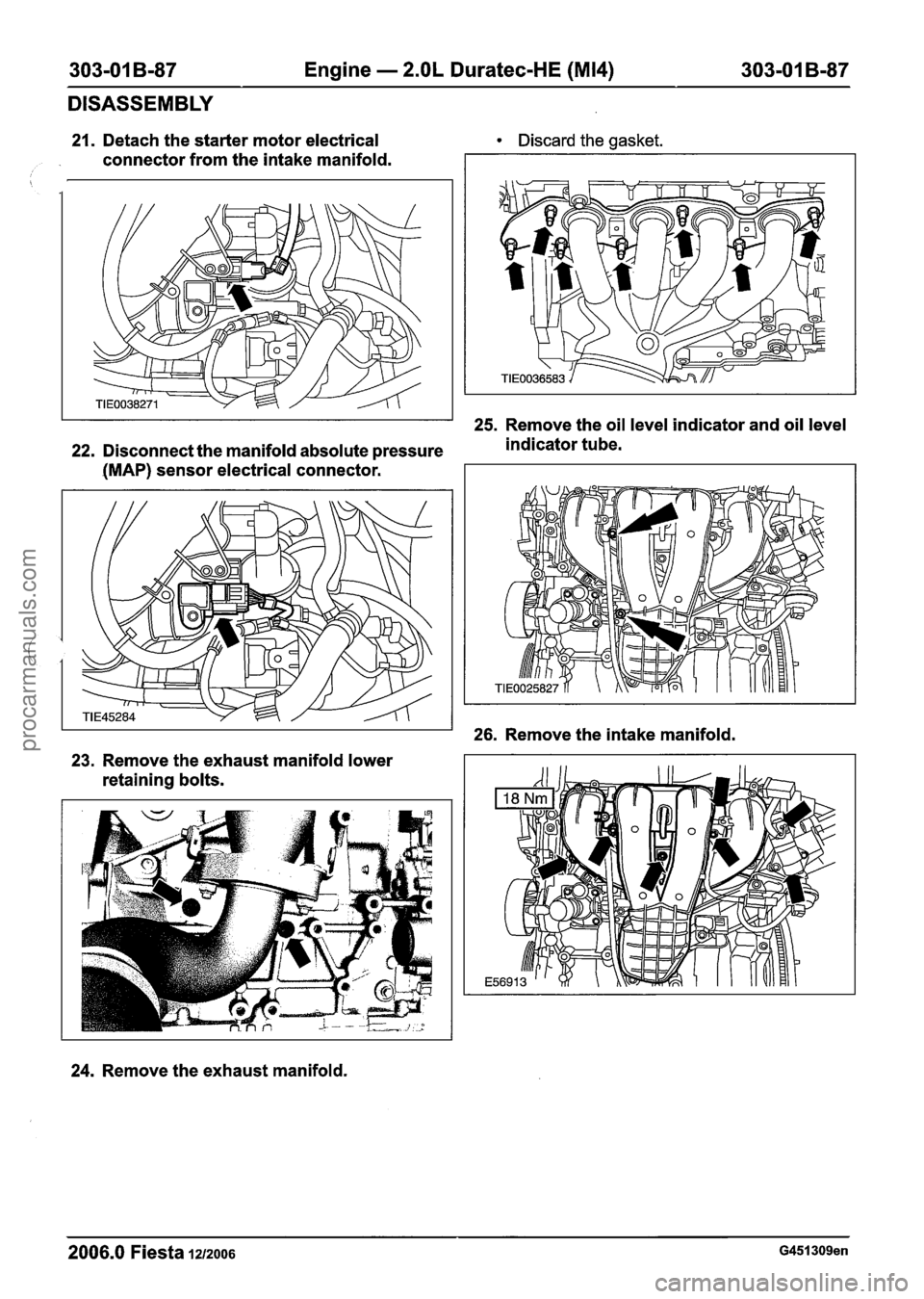
303-01 B-87 Engine - 2.OL Duratec-HE (M14) 303-01 B-87
DISASSEMBLY
21. Detach the starter motor electrical
connector from the intake manifold. Discard the
gasket.
25. Remove the oil level indicator and oil level
22. Disconnect the manifold absolute pressure indicator
tube.
(MAP) sensor electrical connector.
26. Remove the intake manifold.
23. Remove the exhaust manifold lower
retaining bolts.
24. Remove the exhaust manifold.
2006.0 Fiesta 1212006 G451309en
procarmanuals.com
Page 710 of 1226
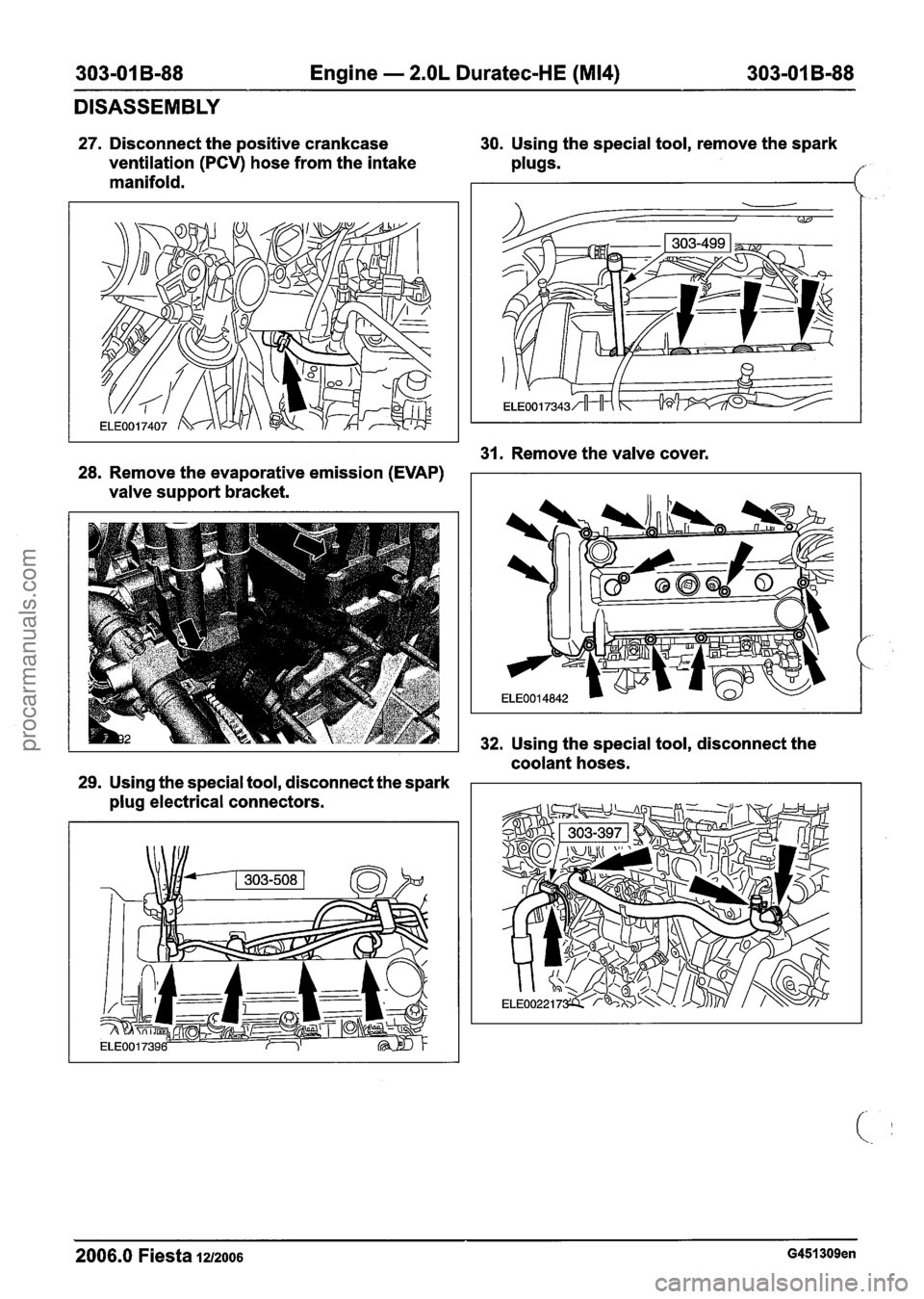
303-01 B-88 Engine - 2.OL Duratec-HE (M14) 303-01 B-88
DISASSEMBLY
27. Disconnect the positive crankcase
ventilation
(PCV) hose from the intake
manifold. 30.
Using the special tool, remove the spark
plugs.
31. Remove the valve cover.
28. Remove the evaporative emission
(EVAP)
valve support bracket.
32. Using the special tool, disconnect the
coolant hoses.
29. Using the special tool, disconnect the spark
plug electrical connectors.
2006.0 Fiesta 1212006 G451309en
procarmanuals.com