body system FORD FIESTA 2007 User Guide
[x] Cancel search | Manufacturer: FORD, Model Year: 2007, Model line: FIESTA, Model: FORD FIESTA 2007Pages: 1226, PDF Size: 61.26 MB
Page 332 of 1226
211 -00-12 Steering System - General Information 211-00-12
DIAGNOSIS AND TESTING
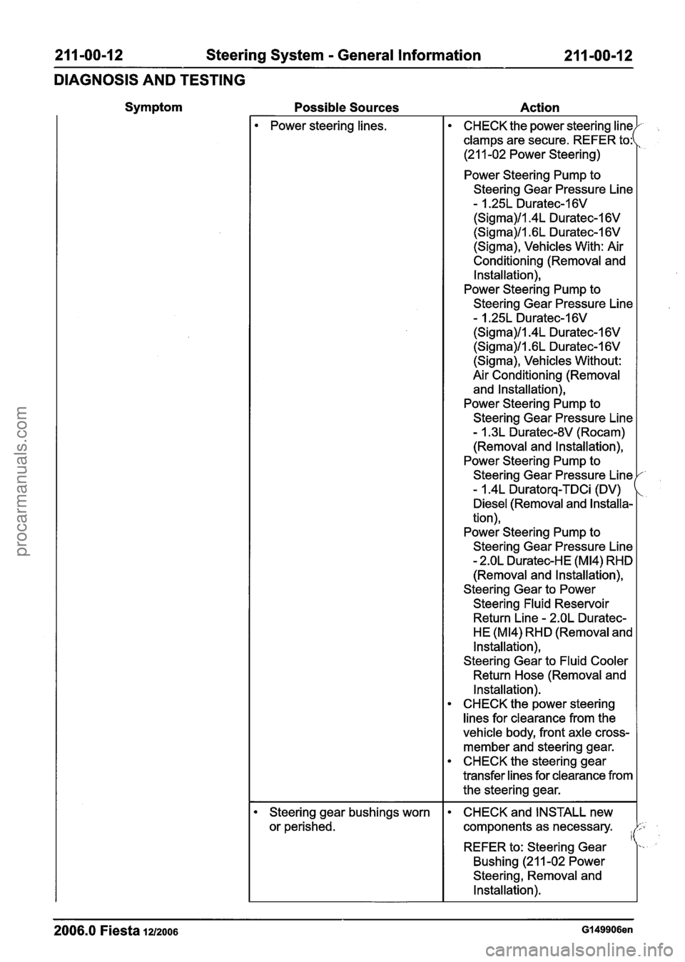
Symptom Possible Sources Action
Power steering lines.
Steering gear bushings worn
or perished.
2006.0 Fiesta 12/2006 Gl49906en
CHECK the power steering lin
clamps are secure. REFER to:
(21 1-02 Power Steering)
Power Steering Pump to
Steering Gear Pressure Line
- 1.25L Duratec-1 6V
(Sigma)/l.4L Duratec-1 6V
(Sigma)/l .6L Duratec-1 6V
(Sigma), Vehicles With: Air
Conditioning
(Removal and
Installation),
Power Steering Pump to
Steering Gear Pressure Line
- 1.25L Duratec-1 6V
(Sigma)/l.4L Duratec-1 6V
(Sigma)/l .6L Duratec-1 6V
(Sigma), Vehicles Without:
Air Conditioning
(Removal
and Installation),
Power Steering Pump to
Steering Gear Pressure Line
- I .3L Duratec-8V (Rocam)
(Removal and Installation),
Power Steering Pump to
Steering Gear Pressure Line
- I .4L Duratorq-TDCi (DV)
Diesel (Removal and Installa-
tion),
Power Steering Pump to
Steering Gear Pressure Line
- 2.OL Duratec-HE (M14) RHD
(Removal and Installation),
Steering Gear to Power
Steering
Fluid Reservoir
Return Line
- 2.OL Duratec-
HE
(M14) RHD (Removal and
Installation),
Steering Gear to Fluid Cooler
Return Hose (Removal and
Installation).
CHECK the power steering
lines for clearance from the
vehicle body, front axle cross-
member and steering gear.
CHECK the steering gear
transfer
lines for clearance from
the steering gear.
CHECK and INSTALL new
components as necessary.
I REFER to: Steering Gear
Bushing (21 1-02 Power
Steering,
Removal and
Installation).
procarmanuals.com
Page 335 of 1226

21 1-00-1 5 Steering System - General Information 21 I -00-1 5
DIAGNOSIS AND TESTING
2. With the road wheels in the straight ahead
position, gently turn the steering wheel to the
1 left and the right to check free play in the
steering linkage.
3. There should be no excessive free play at the
steering wheel rim. If there is excessive free
play, CHECK the tie-rod inner and outer ball
joints, REFER to Tie-Rod Component Test in
this procedure. CHECK the steering column
universal joint, REFER to Steering Column
Universal Joint Component Test in this
procedure. If there is no free play in the tie-rod
and the steering column, install a new steering
gear.
REFER to: Steering Gear (211-02 Power
Steering, Removal and installation).
Tie-Rod
A CAUTI0N:The steering gear boots must be
handled carefully to avoid damage. Use
new steering gear boot clamps when
installing the steering gear boots.
N0TE:Noises such as knocks, which may appear
to originate from the steering linkage, may also be
( , generated by front suspension components.
1. Raise and support the vehicle. REFER to:
(1 00-02 Jacking and Lifting)
Jacking (Description and Operation),
Lifting (Description and Operation).
3m ACAUTION:T~ prevent damage to the
steering linkage, turn the steering wheel to move the steering linkage to the steering
lock stop.
Turn the steering wheel to position the steering
linkage against the right-hand steering lock stop.
4. N0TE:To isolate the steering gear design
clearance, check the right-hand tie-rod with
the steering held against the right-hand
steering lock stop.
With the aid of another technician holding the
steering against the right-hand steering lock
stop, firmly grasp the right-hand road wheel and
apply a rocking motion to check for any free play
in the tie-rod.
5. Detach the steering gear boot from the steering
gear body and check for free play at the tie-rod
inner ball joint.
2. Firmly grasp the road wheel and apply a rocking 6. If there is free play at the tie-rod inner ball joint,
motion to check for any free play in the wheel
install a new tie-rod.
bearing or suspension components.
REFER to: Tie Rod (211-03 Steering Linkage,
Removal and installation).
7. If there is free play at the tie-rod end, install a
new tie-rod end.
REFER to: Tie Rod End (21 1-03 Steering
Linkage, Removal and Installation).
2006.0 Fiesta 1212006 GI 49906en
procarmanuals.com
Page 336 of 1226
21 1-00-1 6 Steering System - General Information 21 I -00-1 6
DIAGNOSIS AND TESTING
8m ACAUTION:T~ prevent damage to the
steering linkage, turn the steering wheel to
move the steering linkage to the steering
lock stop.
Turn the steering wheel to position the steering
linkage against the left-hand steering lock stop.
9. N0TE:To isolate the steering gear design
'clearance, check the left-hand
tiemrod with
the steering held against the left-hand
steering lock stop.
With the aid of another technician holding the
steering against the left-hand steering lock stop,
firmly grasp the left-hand road wheel and apply
a rocking motion to check for any free play in
the tie-rod.
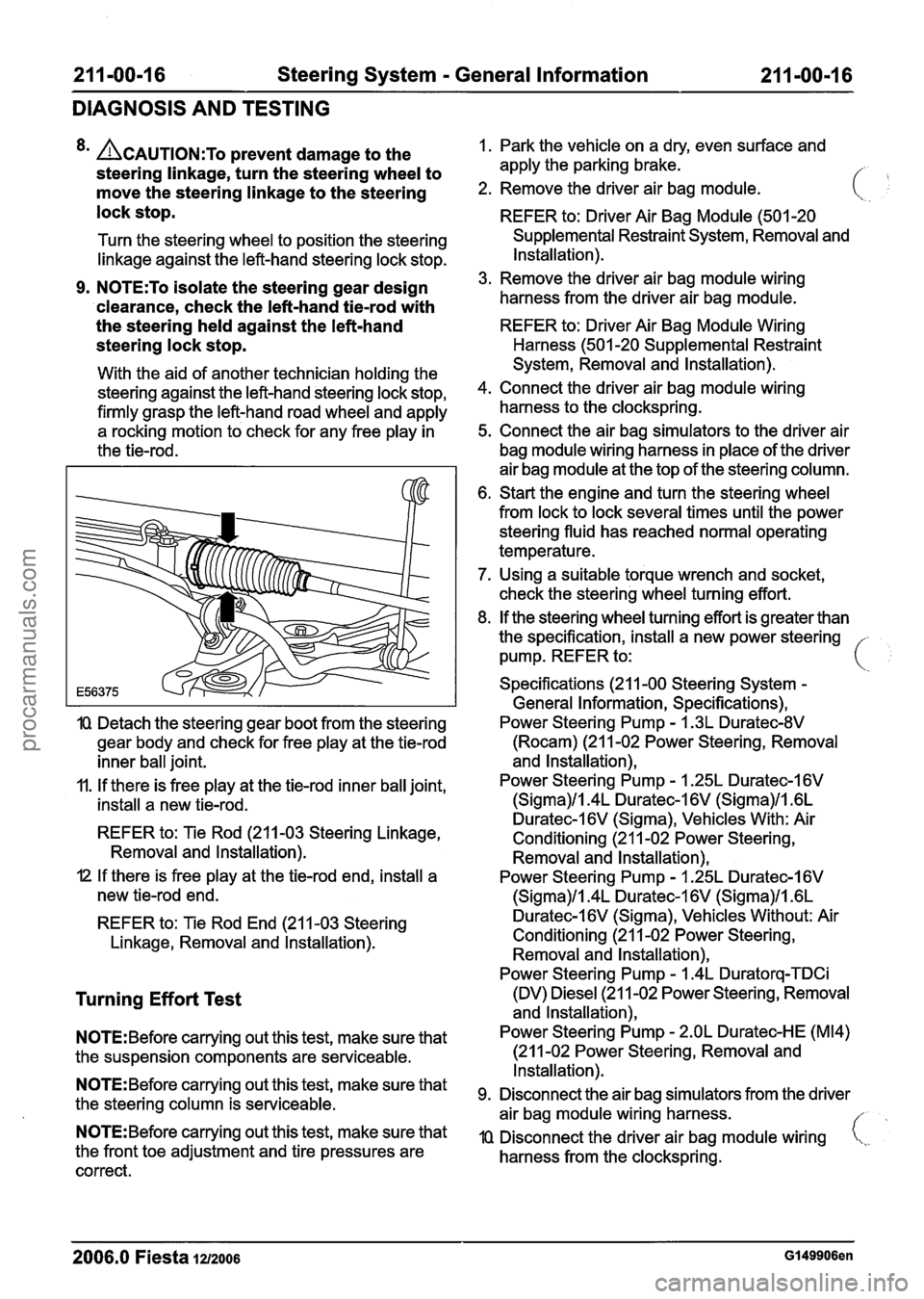
IQ Detach the steering gear boot from the steering
gear body and check for free play at the tie-rod
inner ball joint.
11. If there is free play at the tie-rod inner ball joint,
install a new tie-rod.
REFER to: Tie Rod (211-03 Steering Linkage,
Removal and lnstallation).
I2 If there is free play at the tie-rod end, install a
new tie-rod end.
REFER to: Tie Rod End (21 1-03 Steering
Linkage, Removal and lnstallation).
Turning Effort Test
N0TE:Before carrying out this test, make sure that
the suspension components are serviceable.
N0TE:Before carrying out this test, make sure that
the steering column is serviceable.
N0TE:Before carrying out this test, make sure that
the front toe adjustment and tire pressures are
correct. 1.
Park the vehicle on a dry, even surface and
apply the parking brake.
/- ,
2. Remove the driver air bag module.
REFER to: Driver Air Bag Module (501 -20
Supplemental Restraint System, Removal and
Installation).
3. Remove the driver air bag module wiring
harness from the driver air bag module.
REFER to: Driver Air Bag Module Wiring
Harness (501 -20 Supplemental Restraint
System, Removal and Installation).
4. Connect the driver air bag module wiring
harness to the clockspring.
5. Connect the air bag simulators to the driver air
bag module wiring harness in place of the driver
air bag module at the top of the steering column.
6. Start the engine and turn the steering wheel
from lock to lock several times until the power
steering fluid has reached normal operating
temperature.
7. Using a suitable torque wrench and socket,
check the steering wheel turning effort.
8. If the steering wheel turning effort is greater than
the specification, install a new power steering -
pump. REFER to: i
Specifications (21 1-00 Steering System -
General Information, Specifications),
Power Steering Pump
- I .3L Duratec-8V
(Rocam) (21 1-02 Power Steering, Removal
and lnstallation),
Power Steering Pump
- 1.25L Duratec-1 6V
(Sigma)/l.4L Duratec-1 6V (Sigma)/l .6L
Duratec-l6V (Sigma), Vehicles With: Air
Conditioning (21 1-02 Power Steering,
Removal and lnstallation),
Power Steering Pump
- I .25L Duratec-I 6V
(Sigma)/l.4L Duratec-1 6V (Sigma)/l .6L
Duratec-I 6V (Sigma), Vehicles Without: Air
Conditioning (21 1-02 Power Steering, Removal and lnstallation),
Power Steering Pump
- 1.4L Duratorq-TDCi
(DV) Diesel (21 1-02 Power Steering, Removal
and lnstallation),
Power Steering Pump
- 2.OL Duratec-HE (M14)
(21 1-02 Power Steering, Removal and
Installation).
Disconnect the air bag simulators from the driver
air bag module wiring harness.
//
IQ Disconnect the driver air bag module wiring i,,.
harness from the clockspring.
2006.0 Fiesta 1212006 GI 49906en
procarmanuals.com
Page 342 of 1226
21 1-00-22 Steering System - General Information 21 1-00-22
GENERAL PROCEDURES
Start the engine and slowly turn the steering
wheel from lock to lock and add power
steering fluid until the power steering fluid
in the power steering fluid reservoir does
not drop.
8. Switch OFF the engine and examine the
power steering hose connections, steering
gear boots, power steering valve body and
power steering pump for external leaks.
9. Check the power steering fluid level. Fill the
power steering fluid reservoir to the MAX
mark with the appropriate power steering
fluid.
For additional information, refer to:
Specifications (211
-00 Steering System -
General Information, Specifications).
10.
N0TE:When bleeding the power steering
system the vacuum will decrease. Using
the special tools, maintain a sufficient
vacuum of
38cm-Hg. If the vacuum
decreases by more than
5cm-Hg in 5
minutes, the system should be checked for
leaks.
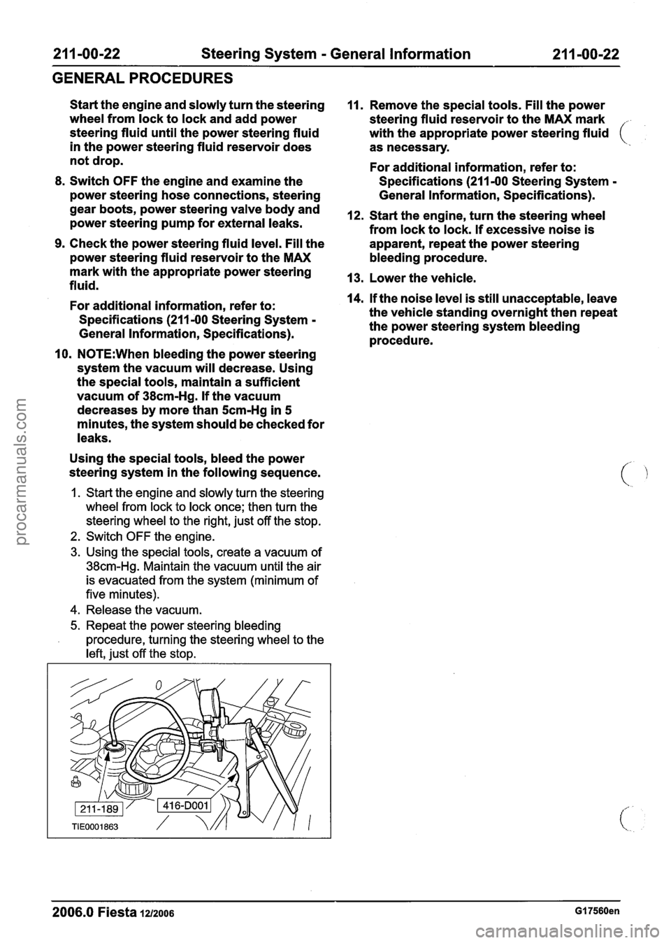
Using the special tools, bleed the power
steering system in the following sequence.
1. Start the engine and slowly turn the steering
wheel from lock to lock once; then turn the
steering wheel to the right, just off the stop.
2. Switch OFF the engine.
3. Using the special tools, create a vacuum of
38cm-Hg. Maintain the vacuum until the air
is evacuated from the system (minimum of
five minutes).
4. Release the vacuum.
5. Repeat the power steering bleeding
procedure, turning the steering wheel to the
left, just off the stop.
11. Remove the special tools. Fill the power
steering fluid reservoir to the MAX mark
.
with the appropriate power steering fluid (
as necessary.
For additional information, refer to:
Specifications (211
-00 Steering System -
General Information, Specifications).
12. Start the engine, turn the steering wheel
from lock to lock. If excessive noise is
apparent, repeat the power steering
bleeding procedure.
13. Lower the vehicle.
14.
If the noise level is still unacceptable, leave
the vehicle standing overnight then repeat
the power steering system bleeding
procedure.
- -
2006.0 Fiesta 121zo06 GI 7560en
procarmanuals.com
Page 395 of 1226

21 1 -02-47 Power Steering 21 1-02-47
REMOVAL AND INSTALLATION
6. Detach the steering gear to power steering All vehicles
fluid cooler return hose from the power
-
/ I steering line.
Right-hand drive vehicles
7. Remove the steering gear heat shield.
9. Disconnect the power steering lines from the
steering gear valve body.
I. Remove the retaining bolt.
2. Rotate the clamp plate.
Allow the fluid to drain into a suitable
container.
Discard the O-ring seals.
10. Remove the steering gear to power steering
fluid cooler return hose.
Installation
1. N0TE:Make sure that the collar on the hose
is fully inserted into the quick release
coupling.
N0TE:Check the power steering lines to steering
gear valve body O-ring seals for damage or fatigue.
8.
N0TE:Note the position of the steering gear Install new O-rin~ seals as necessary. - to power steering fluid cooler return hose to
aid installation. To
install, reverse the removal procedure.
Detach the steering gear to power steering
2. Fill and bleed the power steering system. For
fluid cooler return hose bracket from the additional information, refer
to: (211 -00
steering gear. Steering System
- General
Information)
Power Steering System Filling (General
Procedures),
Power Steering System Bleeding (General
Procedures).
2006.0 Fiesta 1212006 G91967en
procarmanuals.com
Page 812 of 1226
Fuel Charging and Controls - 2.OL
303-04B-4 Duratec-HE (M14) 303-04B-4
DESCRIPTION AND OPERATION
fuel injector to fuel injection supply manifold and
The fuel injectors are activated sequentially by the
the intake manifold is achieved by means of upper
powertrain control module (PCM) which modifies
and lower O-ring seals.
the fuel quantity by adjusting fuel injector opening
times according to the engine operating conditions.
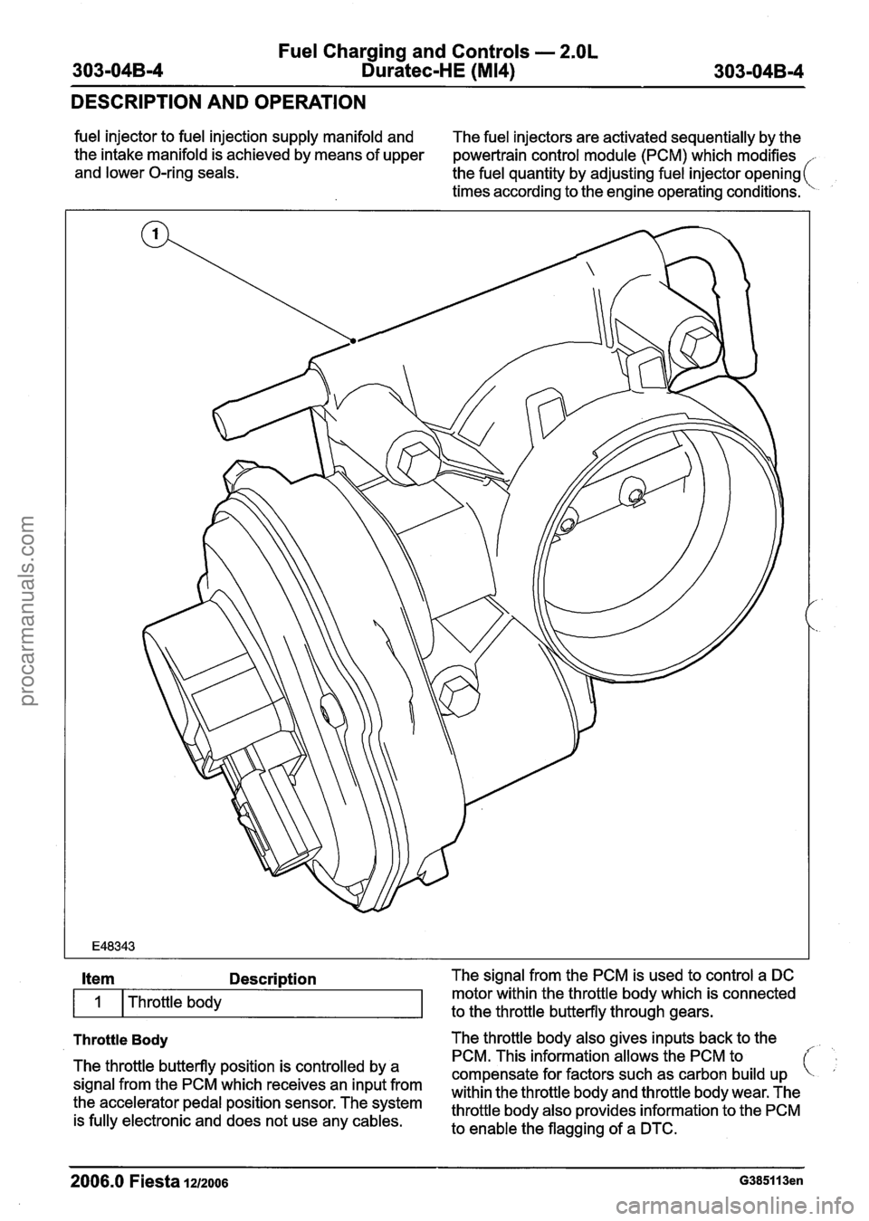
Throttle Body The throttle body also gives inputs back to the
Item Description The signal from the PCM is used to control a DC
The throttle butterfly position is controlled by a
signal from the PCM which receives an input from
the accelerator pedal position sensor. The system
is fully electronic and does not use any cables.
I
PCM. This information allows the PCM to
compensate for factors such as carbon build up
within the throttle body and throttle body wear. The
throttle body also provides information to the PCM
to enable the flagging of a DTC.
Throttle
body
2006.0 Fiesta 1212006 G385113en
motor within the throttle body which is connected
to the throttle butterfly through gears.
procarmanuals.com
Page 814 of 1226
Fuel Charging and Controls - 2.OL
303-04B-6 Duratec-HE (M14) 303-04B-6
DIAGNOSIS AND TESTING
1 6 1 Heated Oxygen sensor (H02s) I
Item Description Fuel supply
1 7 1 Intake manifold I
5
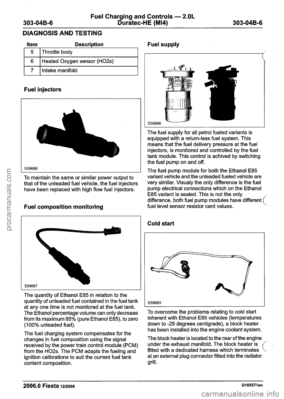
Fuel injectors
Throttle body
The fuel supply for all petrol fueled variants is
equipped with a return-less fuel system. This
means that the fuel delivery pressure at the fuel
injectors, is monitored and controlled by the fuel
tank module. This control is achived by switching
the fuel pump on and off.
The fuel pump module for both the Ethanol E85
TO maintain the same or similar power output to variant vehicle and the unleaded fueled vehicle are
that of the unleaded fuel vehicle, the fuel injectors
very similar, visual^ the only difference is the fuel
have been replaced with high flow fuel injectors. pump electrical connections which on the Ethanol
E85 variant is sealed. This is not the only
differance, both fuel pump modules have different
(
Fuel composition monitoring fuel level sensor resistor card values.
The quantity of Ethanol E85 in relation to the
quantity of unleaded fuel contained in the fuel tank
at any one time is not monitored at the fuel tank.
The Ethanol percentage volume can only decrease
from its maximum 85% (pure Ethanol
E85), to zero
(1 00% unleaded fuel).
The fuel charging system compensates for the
changes in fuel composition using the signal
received by the power train control module (PCM)
from the
H02s. The PCM adapts the fueling and
ignition calibrations to suit the current fuel tank
content composition.
Cold start
To overcome the problems relating to cold start
inherent with Ethanol E85 vehicles (temperatures
down to -29 degrees centigrade), a block heater
has been installed into the engine coolant system.
The block heater is located to the rear of the engine
under the exhaust manifold. The block heater is
fitted with a dedicated harness which terminates at an external plug connector fitted into the radiator
grill.
2006.0 Fiesta 1212006
procarmanuals.com
Page 874 of 1226
303-06-1 0 Starting System 303-06-1 0
DIAGNOSIS AND TESTING
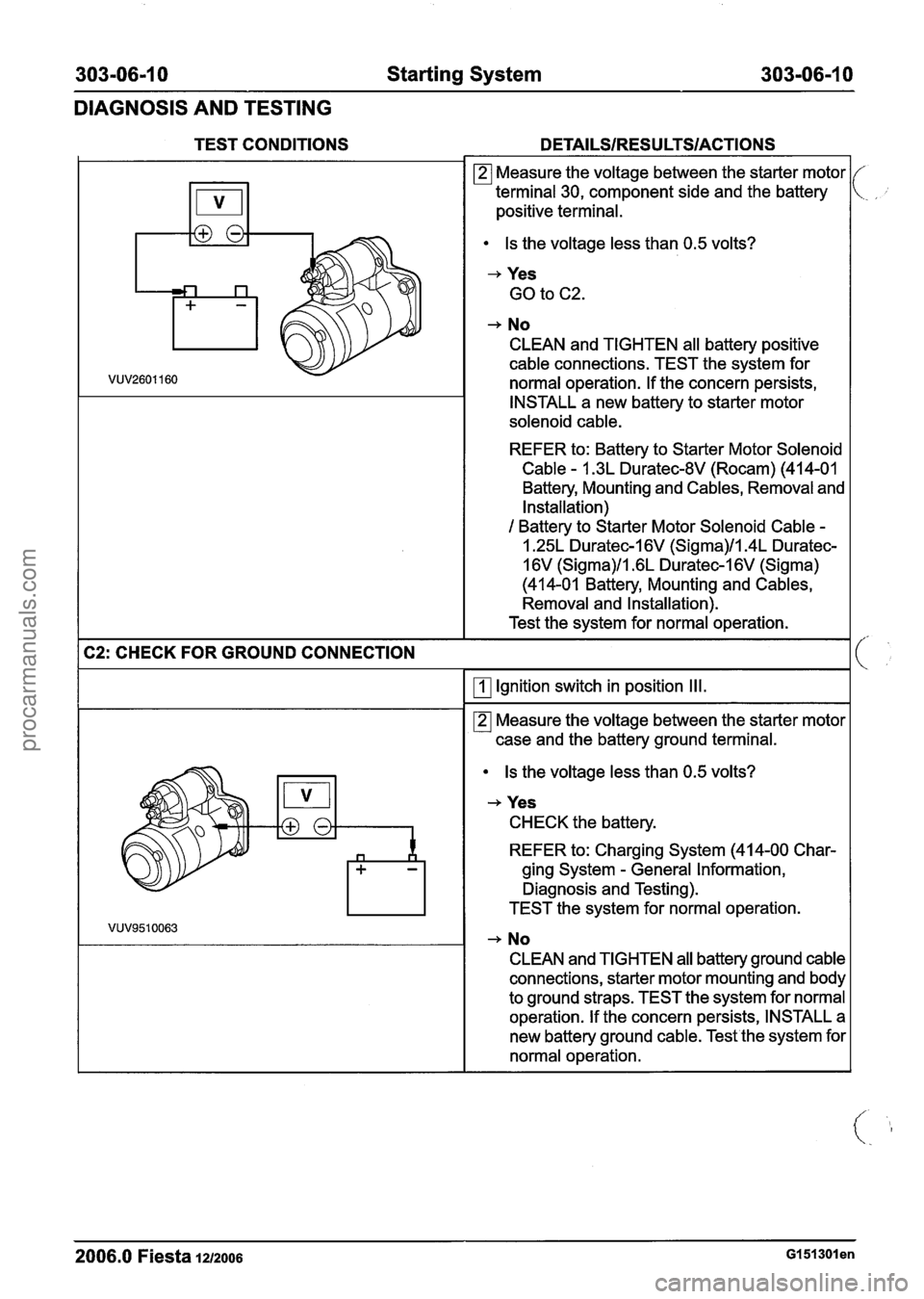
TEST CONDITIONS DETAILSIRESULTSIACTIONS
Measure the voltage between the starter motor
terminal 30, component side and the battery
positive
terminal.
Is the voltage less than 0.5 volts?
+ Yes
GO to C2.
+ No
CLEAN and TIGHTEN all battery positive
cable connections. TEST the system for
normal operation. If the concern persists,
INSTALL a new battery to starter motor
solenoid cable.
REFER to: Battery to Starter Motor Solenoid
Cable - 1.3L Duratec-8V (Rocam) (41 4-01
Battery, Mounting and
Cables, Removal and
Installation)
1 Battery to Starter Motor Solenoid Cable -
1.25L Duratec-1 6V (Sigma)/l.4L Duratec-
16V (Sigma)/l.6L Duratec-1 6V (Sigma)
(414-01 Battery, Mounting and
Cables,
Removal and Installation).
Test the system for normal operation. - - ---
I C2: CHECK FOR GROUND CONNECTION
-
I f
Ignition switch in position Ill.
Is the voltage less than 0.5 volts?
-, Yes
CHECK the battery.
REFER to: Charging System (414-00 Char-
ging System
- General Information,
Diagnosis and Testing).
TEST the system for
normal operation.
+ No
CLEAN and TIGHTEN all battery ground cable
connections, starter motor mounting and body
to ground straps. TEST the system for
normal
operation. If the concern persists, INSTALL a
new battery ground
cable. Testlhe system for
normal operation.
2006.0 Fiesta 1212006 GI 51 301 en
procarmanuals.com
Page 941 of 1226
303-1 4-1 7 Electronic Engine Controls 303-1 4-1 7
DIAGNOSIS AND TESTING
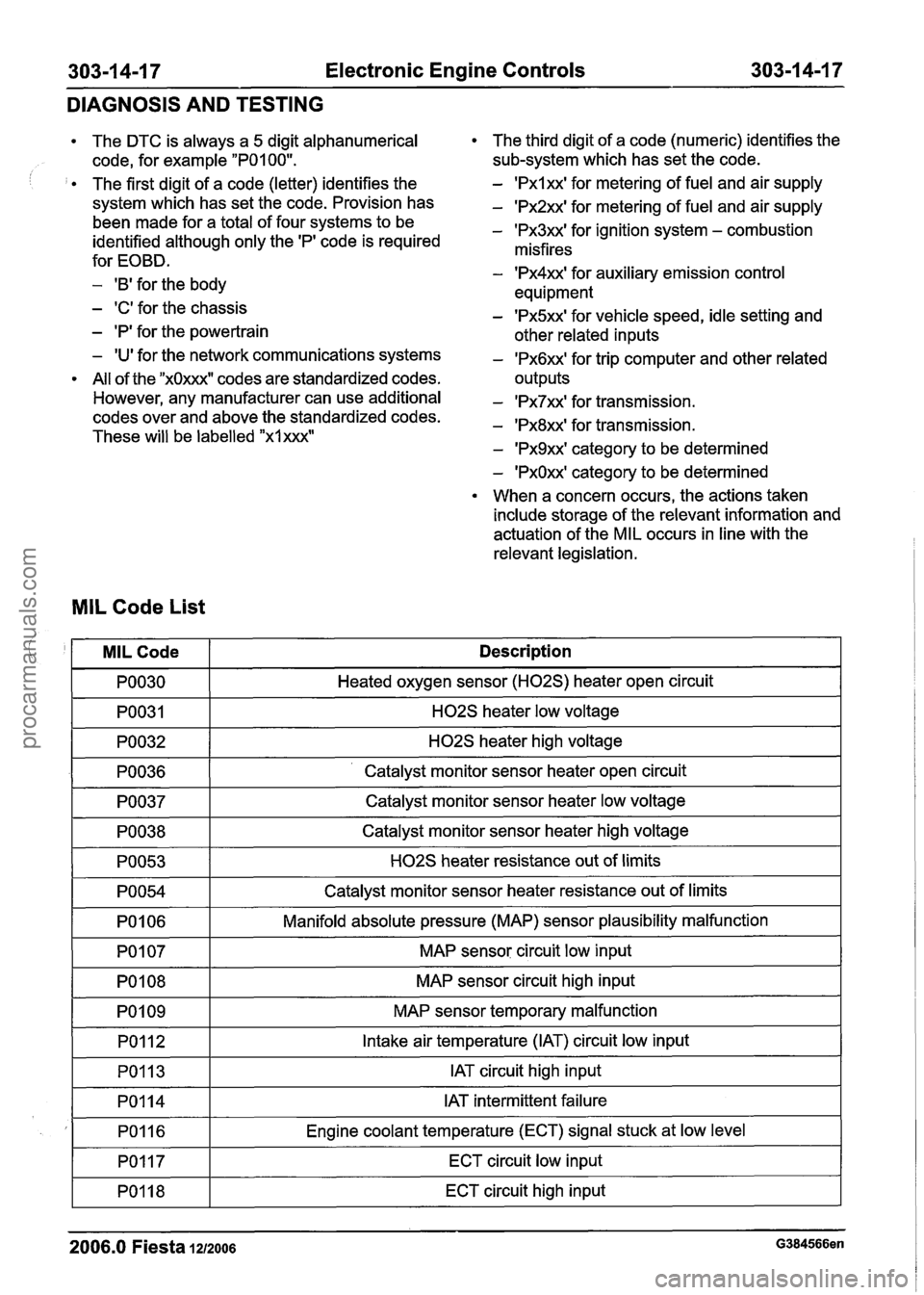
The DTC is always a 5 digit alphanumerical
code, for example
"POI 00".
The first digit of a code (letter) identifies the
system which has set the code. Provision has
been made for a total of four systems to be
identified although only the
'PI code is required
for EOBD.
- 'B' for the body
- 'C' for the chassis
- 'P' for the powertrain
- 'U' for the network communications systems
All of the
"xOxxxW codes are standardized codes.
However, any manufacturer can use additional
codes over and above the standardized codes.
These will be labelled
"xlxxx"
The third digit of a code (numeric) identifies the
sub-system which has set the code.
- 'Pxlxx' for metering of fuel and air supply
- 'Px2xx' for metering of fuel and air supply
- 'Px3xx' for ignition system - combustion
misfires
- 'Px4xx' for auxiliary emission control
equipment
- 'Px5xx' for vehicle speed, idle setting and
other related inputs
- 'Px6xx' for trip computer and other related
outputs
- 'Px7xx' for transmission.
- 'Px8xx' for transmission.
- 'Px9xx' category to be determined
- 'PxOxx' category to be determined
When a concern occurs, the actions taken
include storage of the relevant information and
actuation of the MIL occurs in line with the
relevant legislation.
MIL Code List
I PO030 I Heated oxygen sensor (H02S) heater open circuit I
! '
-1 H02S heater low voltage I
I PO032 I H02S heater high voltage I
MILCode
PO036 1- ' Catalyst monitor sensor heater open circuit I
Description
PO037
I PO054 I Catalyst monitor sensor heater resistance out of limits I
Catalyst monitor sensor heater low voltage
PO038
PO053
I PO106 I Manifold absolute pressure (MAP) sensor plausibility malfunction I
-
Catalyst monitor sensor heater high voltage
H02S heater resistance out of limits
I PO107 I MAP sensor circuit low input I
PO108
PO1 09 MAP sensor
circuit high input
MAP sensor temporary malfunction
PO1 12
PO113
I PO117 I ECT circuit low input I
Intake air temperature (IAT) circuit low input
IAT circuit high input
I
2006.0 Fiesta 1212006 G384566en
PO114
PO1 16
PO118
IAT intermittent failure
Engine coolant temperature (ECT) signal stuck at low level
ECT circuit high input
procarmanuals.com
Page 944 of 1226
303-1 4-20 Electronic Engine Controls 303-1 4-20
DIAGNOSIS AND TESTING
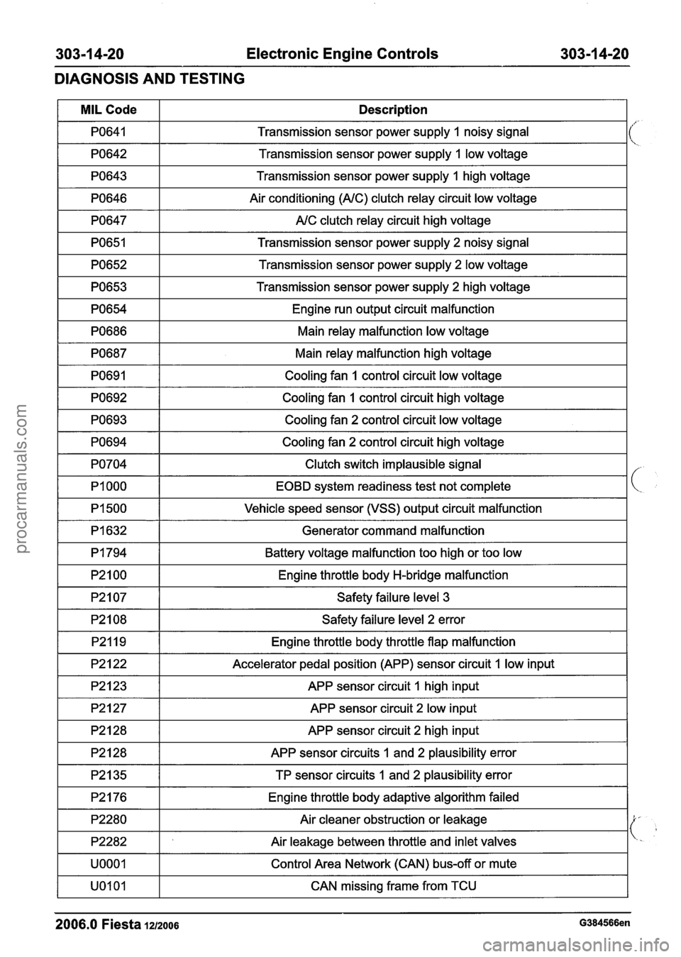
1 PO643 1 Transmission sensor power supply 1 high voltage I
MIL Code
PO641
PO642
1 PO646 1 Air conditioning (NC) clutch relay circuit low voltage I
1 PO647 1 NC clutch relay circuit high voltage I
Description
Transmission sensor power supply 1 noisy signal
Transmission sensor power supply
I low voltage
I PO651 I Transmission sensor power supply 2 noisy signal I
i
PO652
PO653
Transmission sensor power supply 2 low voltage
Transmission sensor power supply
2 high voltage
PO654
PO686
1 PO692 1 Cooling fan 1 control circuit high voltage I
Engine run output circuit malfunction
Main relay malfunction low voltage
PO687
PO691
1 PO693 1 Cooling fan 2 control circuit low voltage I
Main relay malfunction high voltage
Cooling fan
1 control circuit low voltage
1 PO694 1 Cooling fan 2 control circuit high voltage I
I PI500 I Vehicle speed sensor (VSS) output circuit malfunction I
PO704
PI 000
Generator command malfunction I
Clutch switch implausible signal
EOBD system readiness test not complete
I P2107 I Safety failure level 3 I
PI 794
P2100
I P2108 I Safety failure level 2 error I
Battery voltage malfunction too high or too low
Engine throttle body H-bridge malfunction
APP sensor circuit 1 high input I
P2119
P2122
1 P2127 1 APP sensor circuit 2 low input I
Engine throttle body throttle flap malfunction
Accelerator pedal position (APP) sensor circuit
1 low input
1 P2128 1 APP sensor circuit 2 high input I
1 P2176 1 Engine throttle body adaptive algorithm failed 1
P2128
P2135
APP sensor circuits I and 2 plausibility error
TP sensor circuits 1 and 2 plausibility error
I UOOOl I Control Area Network (CAN) bus-off or mute I
P2280
P2282
I UOlOl I CAN missing frame from TCU I
Air cleaner obstruction or leakage
Air leakage between throttle and inlet valves
2006.0 Fiesta 1212006 G384566en
procarmanuals.com