rear suspension FORD FIESTA 2007 User Guide
[x] Cancel search | Manufacturer: FORD, Model Year: 2007, Model line: FIESTA, Model: FORD FIESTA 2007Pages: 1226, PDF Size: 61.26 MB
Page 91 of 1226

204-00-1 I Suspension System - General Information 204-00-1 I
DIAGNOSIS AND TESTING
PINPOINT TEST B : EXCESSIVE NOISE
1 TEST CONDITIONS DETAILSIRESU LTSIACTIONS
2006.0 Fiesta 1212006 Gl49885en
B1: INSPECT ALL STRUT AND SPRING ASSEMBLY AND SHOCK ABSORBER MOUNTING BOLTS
AND NUTS
lnspect the strut and spring assembly and shock
absorber mounting bolts and nuts.
Are the mounting bolts or nuts loose or
broken?
+ Yes
TIGHTEN or INSTALL new mounting bolts
and nuts. REFER to:
Specifications (204-0 1 Front Suspension, Specifications),
Specifications (204-02 Rear Suspension,
Specifications).
-, No
GO to B2.
B2: INSPECT THE STRUT AND SPRING ASSEMBLIES AND SHOCK ABSORBERS FOR LEAKS - --
N0TE:Make sure that the oil is not from another
source.
lnspect the strut and spring assemblies and
shock absorbers for signs of oil
weepage or
leaks. Refer to
weepage and leakage conditions
in the Strut or Shock Absorber Testing
component test in this procedure.
Are the struts or shock absorbers leaking?
+ Yes
INSTALL new struts or shock absorbers as
necessary. REFER to:
Front Strut and Spring Assembly (204-01 Front
Suspension, Removal and
Installation),
Rear Shock Absorber (204-02 Rear Suspension,
Removal and Installation).
+ No
GO to B3.
procarmanuals.com
Page 92 of 1226

204-00-1 2 Suspension System - General Information 204-00-12
DIAGNOSIS AND TESTING
TEST CONDITIONS DETAILSIRESULTSIACTIONS
1 83: INSPECT THE SPRINGS AND STABILIZER BAR(S) I
lnspect the springs and stabilizer bar(s) for
damage.
Are the springs or stabilizer bar(s) damaged?
-+ Yes
INSTALL new springs or stabilzer bar(s).
REFER to:
Front Strut and Spring Assembly (204-01 Front Suspension, Disassembly and Assembly),
Front Stabilizer Bar (204-01 Front Suspension,
Removal and Installation),
Spring (204-02 Rear Suspension, Removal and
Installation).
I B4: INSPECT THE SUSPENSION BUSHINGS I
lnspect the suspension bushings for excessive
wear or damage.
Are the bushings worn or damaged?
-+ Yes
INSTALL new components as necessary.
REFER to:
Front Stabilizer Bar Bushing (204-01 Front Suspension, Removal and lnstallation),
Lower Arm (204-01 Front Suspension, Removal
and Installation),
Front Strut and Spring Assembly (204-01 Front
Suspension, Removal and lnstallation),
Rear Shock Absorber (204-02 Rear Suspension,
Removal and lnstallation),
Trailing Arm Bushing (204-02 Rear Suspension,
Removal and Installation).
Carry out the Ball Joint Inspection component
test in this procedure.
Is the lower arm ball joint or gaiter damaged?
-+ Yes
INSTALL a new lower arm.
REFER to: Lower Arm (204-01 Front
Suspension, Removal and lnstallation).
2006.0 Fiesta iz1~006 GI 49885en
procarmanuals.com
Page 93 of 1226
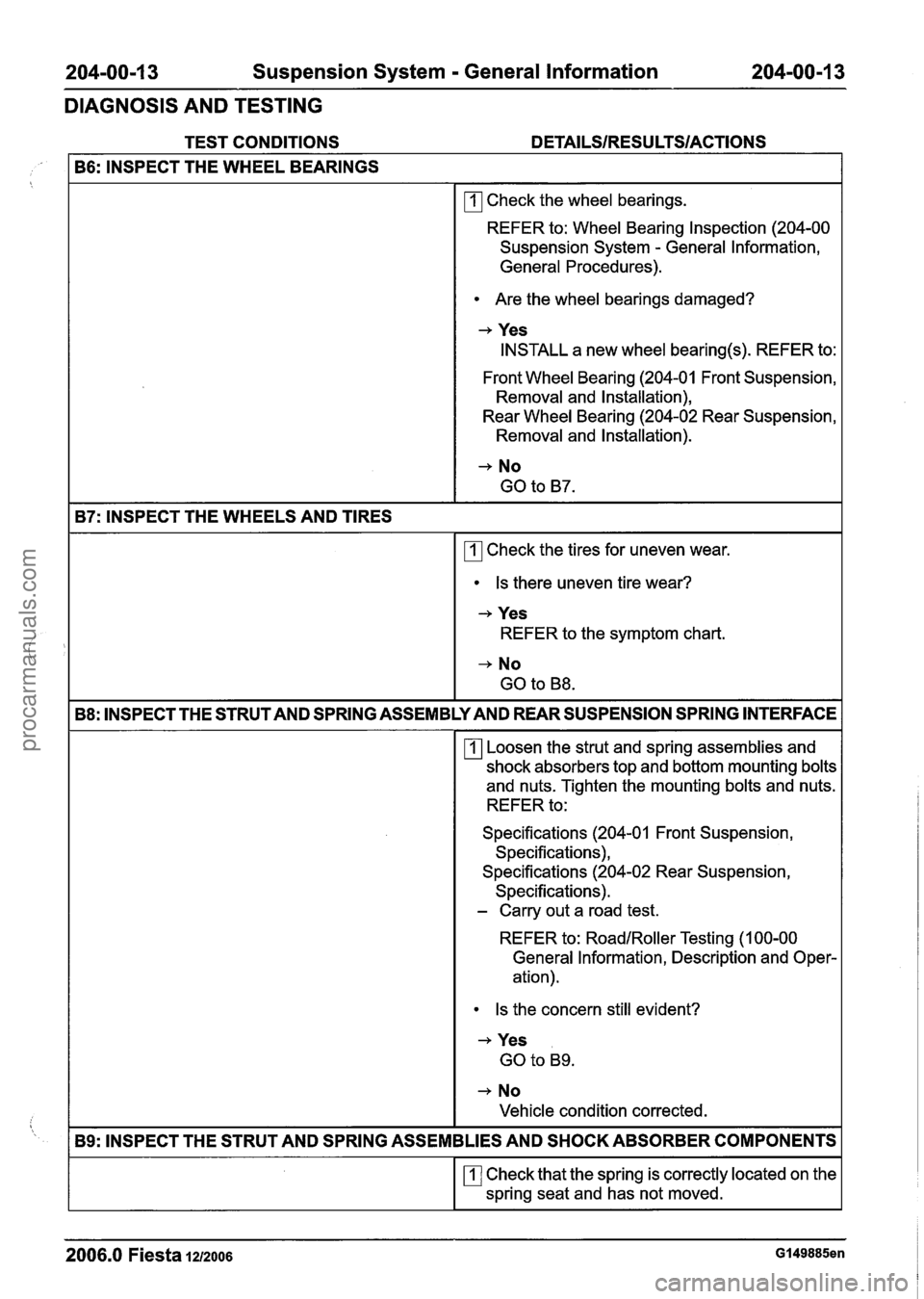
204-00-1 3 Suspension System - General Information 204-00-1 3
DIAGNOSIS AND TESTING
TEST CONDITIONS DETAILSIRESU LTSIACTIONS
B6: INSPECT THE WHEEL BEARINGS
rn Check the wheel bearings.
REFER to: Wheel Bearing Inspection (204-00
Suspension System
- General Information,
General Procedures).
Are the wheel bearings damaged?
-+ Yes
INSTALL a new wheel bearing(s). REFER to:
Front Wheel Bearing (204-01 Front Suspension,
Removal and Installation),
Rear Wheel Bearing (204-02 Rear Suspension,
Removal and Installation).
-+ No
GO to B7.
B7: INSPECT THE WHEELS AND TIRES
rn Check the tires for uneven wear.
Is there uneven tire wear?
-+ Yes
REFER to the symptom chart.
-, No
GO to B8.
B8: INSPECT THE STRUT AND SPRING ASSEMBLY AND REAR SUSPENSION SPRING INTERFACE
Loosen the strut and spring assemblies and
shock absorbers top and bottom mounting bolts
and nuts. Tighten the mounting bolts and nuts.
REFER to:
Specifications (204-01 Front Suspension, Specifications),
Specifications (204-02 Rear Suspension,
Specifications).
- Carry out a road test.
REFER to:
RoadIRoller Testing (1 00-00
General Information, Description and Oper-
ation).
Is the concern still evident?
-+ Yes
GO to B9.
-+ No
Vehicle condition corrected.
B9: INSPECT THE STRUT AND SPRING ASSEMBLIES AND SHOCK ABSORBER COMPONENTS
rn Check that the spring is correctly located on the
spring seat and has not moved.
2006.0 Fiesta 1212006 G149885en
procarmanuals.com
Page 94 of 1226
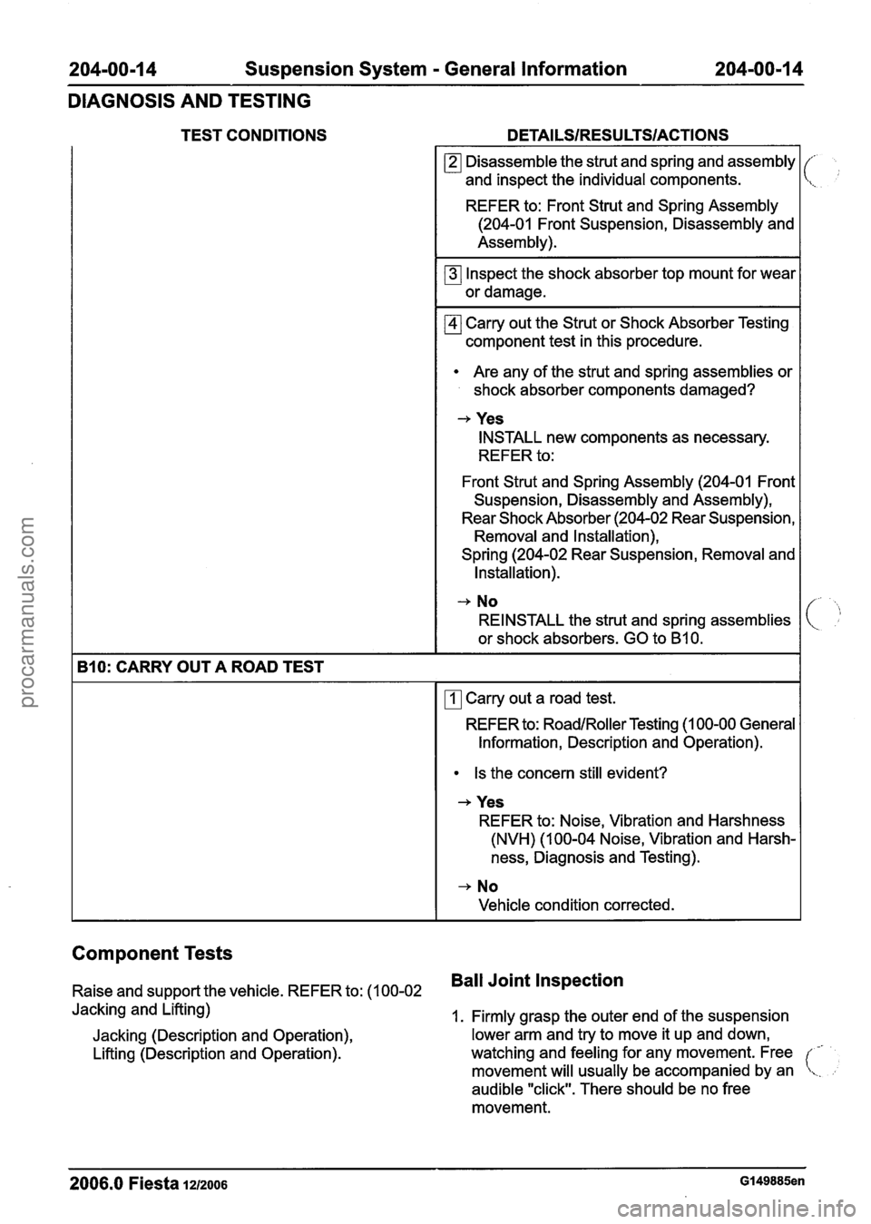
204-00-1 4 Suspension System - General Information 204-00-1 4
DIAGNOSIS AND TESTING
TEST CONDITIONS DETAILSIRESU LTSIACTIONS
Component Tests
Raise and support the vehicle. REFER to: (1 00-02 Ball Joint Inspection
Jacking and Lifting)
1. Firmly grasp the outer end of the suspension
Jacking (Description and Operation), lower arm and
try to move it up and down,
Lifting (Description and Operation). watching and feeling for
any movement. Free
-
movement will usually be accompanied by an !
audible "click". There should be no free
movement.
(,';
B10: CARRY OUT A ROAD TEST
2006.0 Fiesta 1212006 Gl49885en
Disassemble the strut and spring and assembly
and inspect the individual components.
REFER to: Front Strut and Spring Assembly
(204-01 Front Suspension, Disassembly and
Assembly).
Inspect the shock absorber top mount for wear
or damage.
Carry out the Strut or Shock Absorber Testing
component test in this procedure.
Are any of the strut and spring assemblies or
shock absorber components damaged?
-+ Yes
INSTALL new components as necessary.
REFER to:
Front Strut and Spring Assembly (204-01 Front
Suspension, Disassembly and Assembly),
Rear Shock Absorber (204-02 Rear Suspension, Removal and Installation),
Spring (204-02 Rear Suspension, Removal and Installation).
-, No
REINSTALL the strut and spring assemblies
or shock absorbers. GO to
B10.
Carry out a road test.
REFER to:
RoadlRoller Testing (1 00-00 General
Information, Description and Operation).
Is the concern still evident?
-+ Yes
REFER to: Noise, Vibration and Harshness
(NVH) (1 00-04 Noise, Vibration and Harsh-
ness, Diagnosis and Testing).
-+ No
Vehicle condition corrected.
procarmanuals.com
Page 95 of 1226
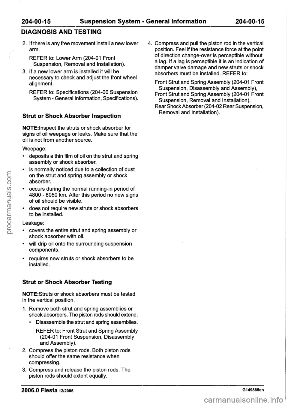
204-00-1 5 Suspension System - General Information 204-00-1 5 1
DIAGNOSIS AND TESTING
2. If there is any free movement install a new lower 4. Compress and pull the piston rod in the vertical
arm. position. Feel if the resistance force at the point
REFER to: Lower Arm (204-01 Front
Suspension, Removal and Installation).
3. If a new lower arm is installed it will be
necessary to check and adjust the front wheel
alignment.
REFER to: Specifications (204-00 Suspension
System
- General Information, Specifications). of direction change-over
is perceptible without
a lag. If a lag is perceptible it is an indication of
damper valve damage and new struts or shock
absorbers must be installed. REFER to:
Front Strut and Spring Assembly (204-01 Front
Suspension, Disassembly and Assembly),
Front Strut and Spring Assembly (204-01 Front
Suspension, Removal and Installation),
Rear Shock Absorber (204-02 Rear Suspension,
Removal and Installation).
Strut or Shock Absorber Inspection
N0TE:lnspect the struts or shock absorber for
signs of oil
weepage or leaks. Make sure that the
oil is not from another source.
Weepage:
deposits a thin film of oil on the strut and spring
assembly or shock absorber.
is normally noticed due to a collection of dust
on the strut and spring assembly or shock
absorber.
occurs during the normal running-in period of
4800
- 8050 km. After this period no new signs
of oil should be visible.
does not require new struts or shock absorbers
to be installed.
Leakage:
covers the entire strut and spring assembly or
shock absorber with oil.
will drip oil onto the surrounding suspension
components.
requires new struts or shock absorbers to be
installed.
Strut or Shock Absorber Testing
N0TE:Struts or shock absorbers must be tested
in the vertical position.
I. Remove both strut and spring assemblies or
shock absorbers. The piston rods should extend.
Disassemble the strut and spring assemblies.
REFER to: Front Strut and Spring Assembly
(204-01 Front Suspension, Disassembly
and Assembly).
2. Compress the piston rods. Both piston rods
should offer the same resistance when
compressing.
3. Compress and release the piston rods. The
piston rods should extent equally.
2006.0 Fiesta 1212006 Gl49885en
procarmanuals.com
Page 100 of 1226
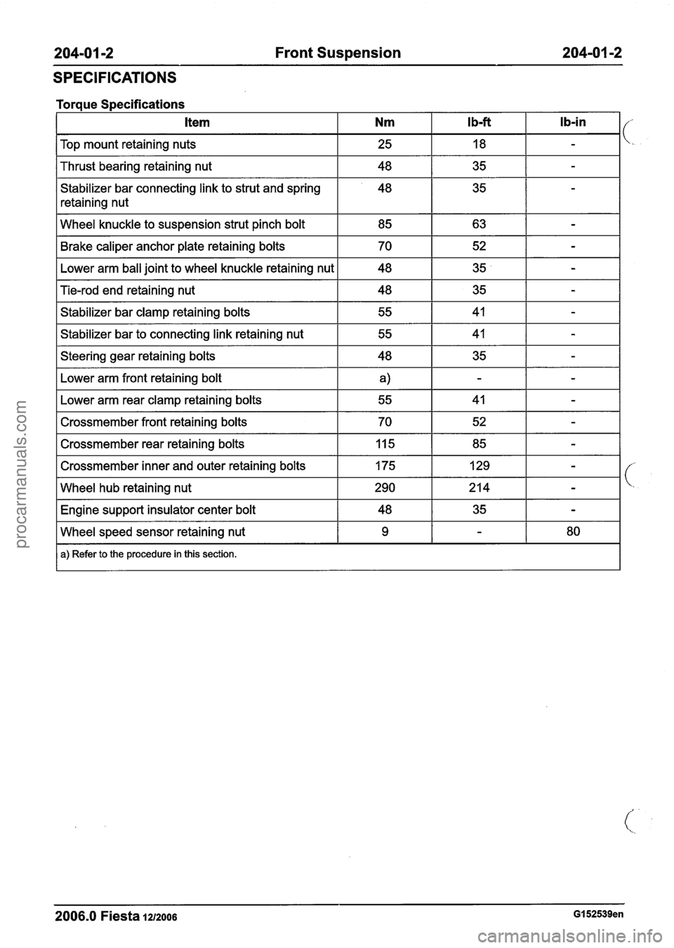
204-01 -2 Front Suspension 204-01 -2
SPECIFICATIONS
I Top mount retaining nuts I 25 I 18 I - I
Torque Specifications
I Thrust bearing retaining nut I 48 I 35 I - I
Stabilizer bar connecting link to strut and spring
retaining nut Ib-in
I Wheel
knuckle to suspension strut pinch bolt I 85 I 63 I - I
Ib-ft Item Nm
Brake caliper anchor plate retaining bolts
Lower arm ball joint to wheel knuckle retaining nut
I Steering gear retaining bolts I 48 I 35 I - I
Tie-rod end retaining nut
Stabilizer bar clamp retaining bolts
Stabilizer bar to connecting link retaining nut
Fb.wer arm front retaining bolt I
70
48
I Lower arm rear clamp retaining bolts I 55 I 41 I - I
48
55
55
I Crossmember front retaining bolts I 70 I 52 I - I
52
35
I Crossmember rear retaining bolts 1 Iq5 1 85 I - I
-
-
35
41
41
I Crossmember inner and outer retaining bolts 1 175 1 129 1 - I
-
-
-
I Wheel hub retaining nut 1290 1214 1 - I
I Engine support insulator center bolt I 48 I 35 I - I
2006.0 Fiesta 1212006 GI 52539en
Wheel speed sensor retaining nut
a) Refer to the procedure in this section.
9 - 80
procarmanuals.com
Page 102 of 1226
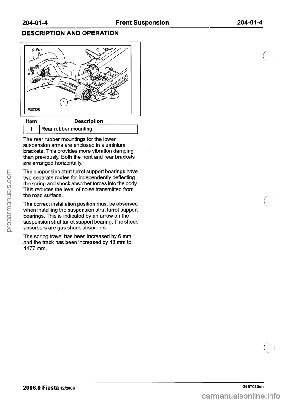
204101 -4 Front Suspension 204-01 -4
DESCRIPTION
AND OPERATION
Item Description
The rear rubber mountings for the lower
suspension arms are enclosed in aluminium
brackets. This provides more vibration damping
than previously. Both the front and rear brackets
are arranged horizontally.
1
The suspension strut turret support bearings have
two separate routes for independently deflecting
the spring and shock absorber forces into the body.
This reduces the level of noise transmitted from
the road surface. Rear rubber
mounting
The correct installation position must be observed
when installing the suspension strut turret support
bearings. This is indicated by an arrow on the
suspension strut turret support bearing. The shock
absorbers are gas shock absorbers.
The spring travel has been increased by
6 mm,
and the track has been increased by
48 mm to
1477 mm.
2006.0 Fiesta 1212006 GI 67080en
procarmanuals.com
Page 106 of 1226
204-0 I -8 Front Suspension 204-01 -8
REMOVAL AND INSTALLATION
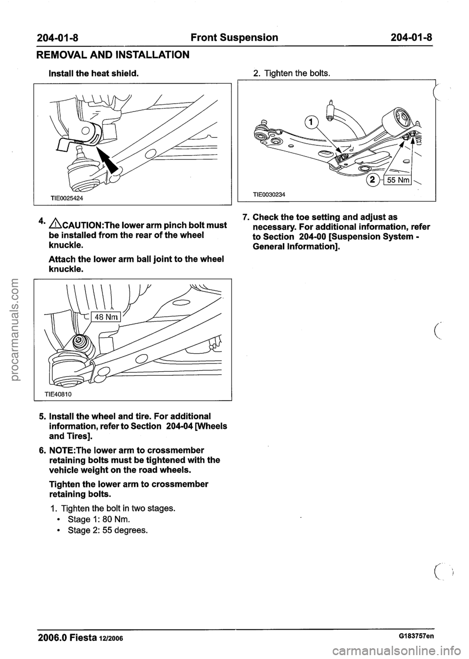
Install the heat shield. 2. Tighten the bolts.
7. Check the toe setting and adjust as
4m ACAUTION:T~~ lower arm pinch bolt must necessary. For additional information, refer
be installed from the rear of the wheel
to Section 204-00 [Suspension System -
knuckle. General Information].
Attach the lower arm ball joint to the wheel
knuckle.
5, Install the wheel and tire. For additional
information, refer to Section
204-04 wheels
and Tires].
6. N0TE:The lower arm to crossmember
retaining bolts must be tightened with the
vehicle weight on the road wheels.
Tighten the lower arm to crossmember
retaining bolts.
1. Tighten the bolt in two stages.
Stage I: 80 Nm.
Stage 2: 55 degrees.
2006.0 Fiesta 1212006 GI 83757en
procarmanuals.com
Page 114 of 1226
204-01 -1 6 Front Suspension 204-01 -1 6
REMOVAL AND INSTALLATION
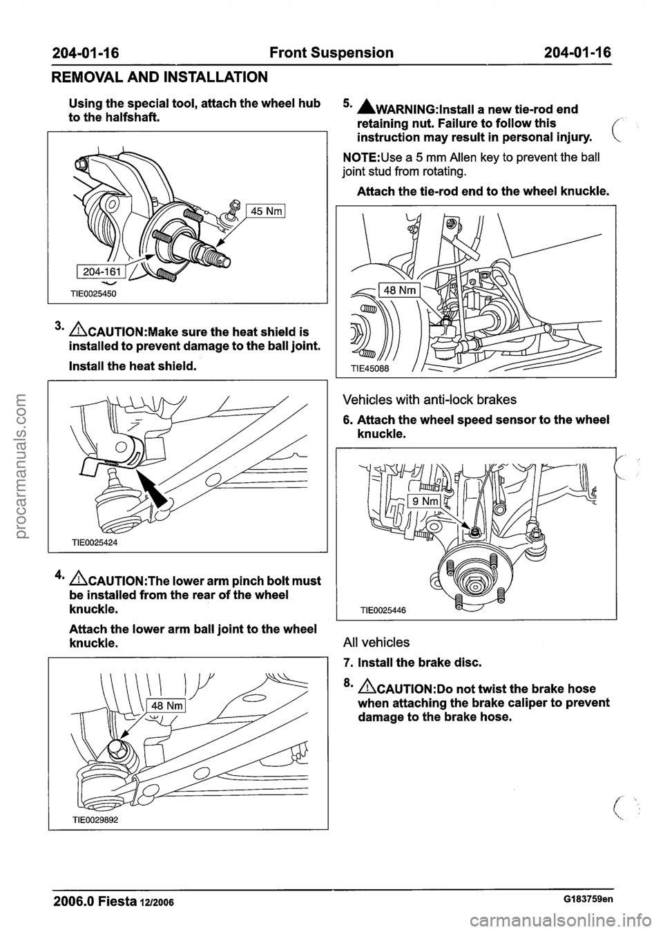
Using the special tool, attach the wheel hub 5. AWARNING:lnstall a new tie-rod end to the halfshaft.
retaining nut. Failure to follow this f
3m ACAUTION:M~~~ sure the heat shield is
installed to prevent damage to the ball joint.
Install the heat shield.
4m &AUTION:T~~ lower arm pinch bolt must
be installed from the rear of the wheel
knuckle. instruction
may result in personal injury.
N0TE:Use a 5 mm Allen key to prevent the ball
joint stud from rotating.
Attach the tie-rod end to the wheel knuckle.
Vehicles with anti-lock brakes
6. Attach the wheel speed sensor to the wheel
knuckle.
Attach the lower arm ball joint to the wheel
knuckle.
All vehicles
7. Install the brake disc.
8m &AUTION:DO not twist the brake hose
when attaching the brake caliper to prevent
damage to the brake hose.
2006.0 Fiesta 1212006 GI 83759en
procarmanuals.com
Page 118 of 1226
204-01 -20 Front Suspension 204-01 -20
REMOVAL AND INSTALLATION
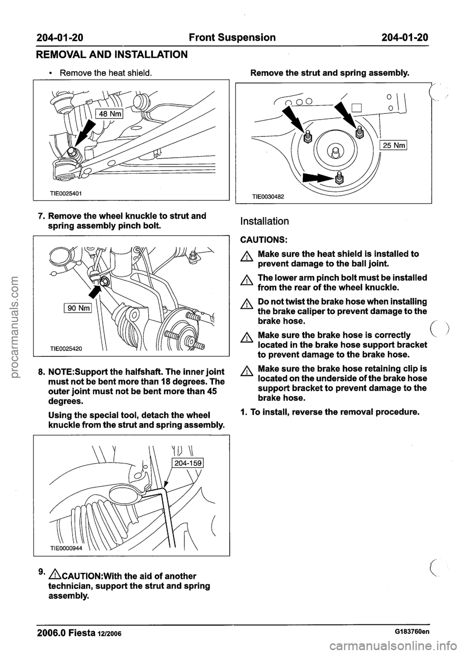
Remove the heat shield.
7. Remove the wheel knuckle to strut and
spring assembly pinch bolt.
8. N0TE:Suppot-t the halfshaft. The inner joint
must not be bent more than
I8 degrees. The
outer joint must not be bent more than
45
degrees.
Using the special tool, detach the wheel
knuckle from the strut and spring assembly.
ACAUTION:~~~~ the aid of another
technician, support the strut and spring
assembly. Remove
the strut and spring assembly.
Installation
CAUTIONS:
A Make sure the heat shield is installed to
prevent damage to the ball joint.
The lower arm pinch bolt must be installed
from the rear of the wheel knuckle.
A Do not twist the brake hose when installing
the brake caliper to prevent damage to the
brake hose.
f- ,
A Make sure the brake hose is correctly
located in the brake hose support bracket
to prevent damage to the brake hose.
A Make sure the brake hose retaining clip is
located on the underside of the brake hose
support bracket to prevent damage to the
brake hose.
I. To install, reverse the removal procedure.
2006.0 Fiesta 1~12006 GI 83760en
procarmanuals.com