steering wheel adjustment FORD FIESTA 2007 Workshop Manual
[x] Cancel search | Manufacturer: FORD, Model Year: 2007, Model line: FIESTA, Model: FORD FIESTA 2007Pages: 1226, PDF Size: 61.26 MB
Page 326 of 1226

211 -00-6 Steering System = General Information 21 1 =OO-6
DIAGNOSIS AND TESTING
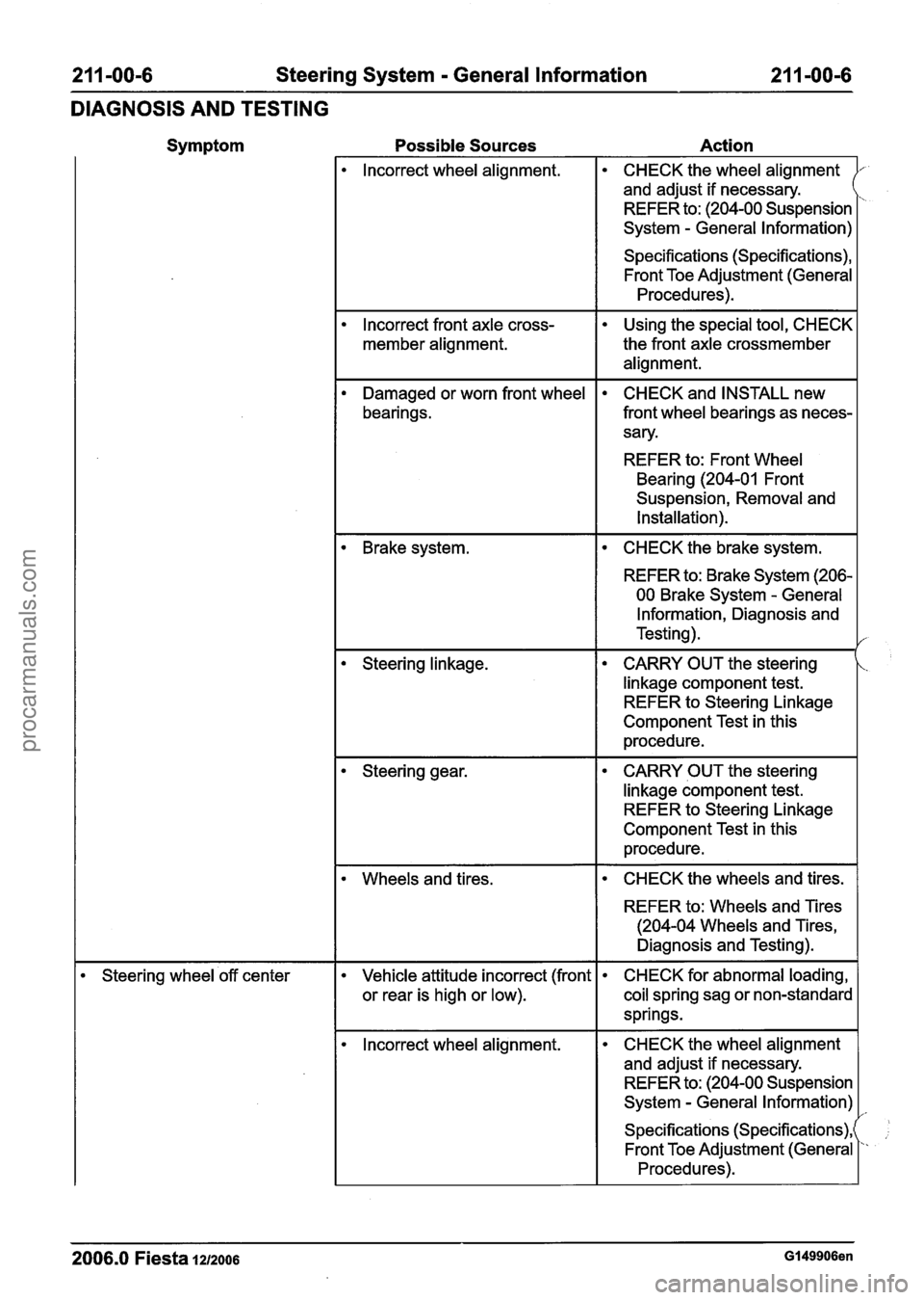
Symptom Possible Sources Action
lncorrect wheel alignment. CHECK the wheel alignment
and adjust if necessary.
REFER to: (204-00 Suspension
System
- General Information) r
Specifications (Specifications), Front Toe Adjustment (General
Procedures).
lncorrect front axle cross-
member alignment.
Using the special tool, CHECK
the front axle crossmember
alignment.
Damaged or worn front wheel
bearings. CHECK and INSTALL new
front wheel bearings as neces-
sary.
REFER to: Front Wheel
Bearing (204-01 Front
Suspension, Removal and
Installation).
I CHECK the brake system. I
REFER to: Brake System (206-
00 Brake System
- General
Information, Diagnosis and
Testing).
CARRY OUT the steering
linkage component test.
REFER to Steering Linkage
Component Test in this
procedure.
CARRY OUT the steering
linkage component test.
REFER to Steering Linkage
Component Test in this
procedure.
Wheels and tires. I CHECK the wheels and tires. I
REFER to: Wheels and Tires
(204-04 Wheels and Tires,
Diagnosis and Testing).
Steering wheel 'off center Vehicle attitude incorrect (front
or rear is high or low). CHECK
for abnormal loading,
coil spring sag or non-standard
springs.
lncorrect wheel alignment. CHECK
the wheel alignment
and adjust if necessary.
REFER to: (204-00 Suspension
System
- General Information)
Specifications (Specifications),
Front Toe Adjustment (General
Procedures).
2006.0 Fiesta 1212006 GI 49906en
procarmanuals.com
Page 327 of 1226

21 1-00-7 Steering System - General Information 21 1-00-7
DIAGNOSIS AND TESTING
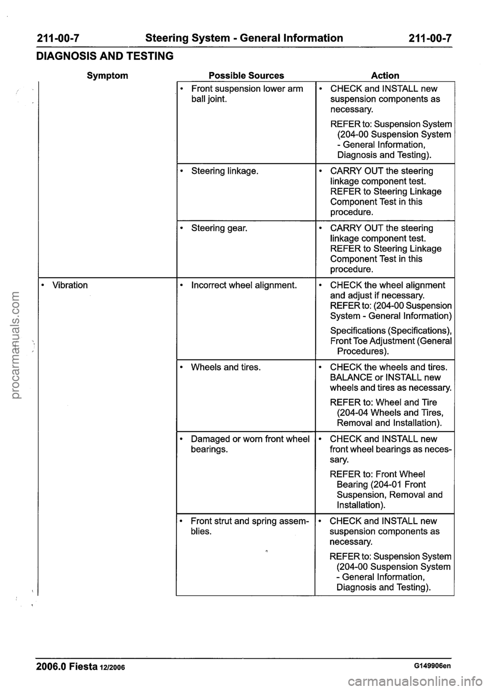
Symptom
Vibration
Possible Sources Action
Front suspension lower arm
ball joint. CHECK
and INSTALL new
suspension components as
necessary.
REFER to: Suspension System
(204-00 Suspension System
- General Information,
Diagnosis and Testing).
Steering linkage. CARRY OUT the steering
linkage component test. REFER to Steering Linkage
Component Test in this
procedure.
Steering gear. CARRY OUT the steering
linkage component test. REFER to Steering Linkage
Component Test in this
procedure.
Incorrect wheel alignment. CHECK the wheel alignment
and adjust if necessary.
REFER to: (204-00 Suspension
System
- General Information)
Specifications (Specifications), Front Toe Adjustment (General
Procedures).
Wheels and tires.
CHECK the wheels and tires.
BALANCE or INSTALL new
wheels and tires as necessary.
REFER to: Wheel and Tire
(204-04 Wheels and Tires,
Removal and
Installation).
Damaged or worn front wheel
bearings. CHECK
and INSTALL new
front wheel bearings as neces-
sary.
REFER to: Front Wheel
Bearing
(204-01 Front
Suspension, Removal and
Installation).
Front strut and spring assem-
blies. CHECK
and INSTALL new
suspension components as
necessary.
REFER to: Suspension System
(204-00 Suspension System
- General Information,
Diagnosis and Testing).
2006.0 Fiesta 1212006 GI 49906en
procarmanuals.com
Page 336 of 1226

21 1-00-1 6 Steering System - General Information 21 I -00-1 6
DIAGNOSIS AND TESTING
8m ACAUTION:T~ prevent damage to the
steering linkage, turn the steering wheel to
move the steering linkage to the steering
lock stop.
Turn the steering wheel to position the steering
linkage against the left-hand steering lock stop.
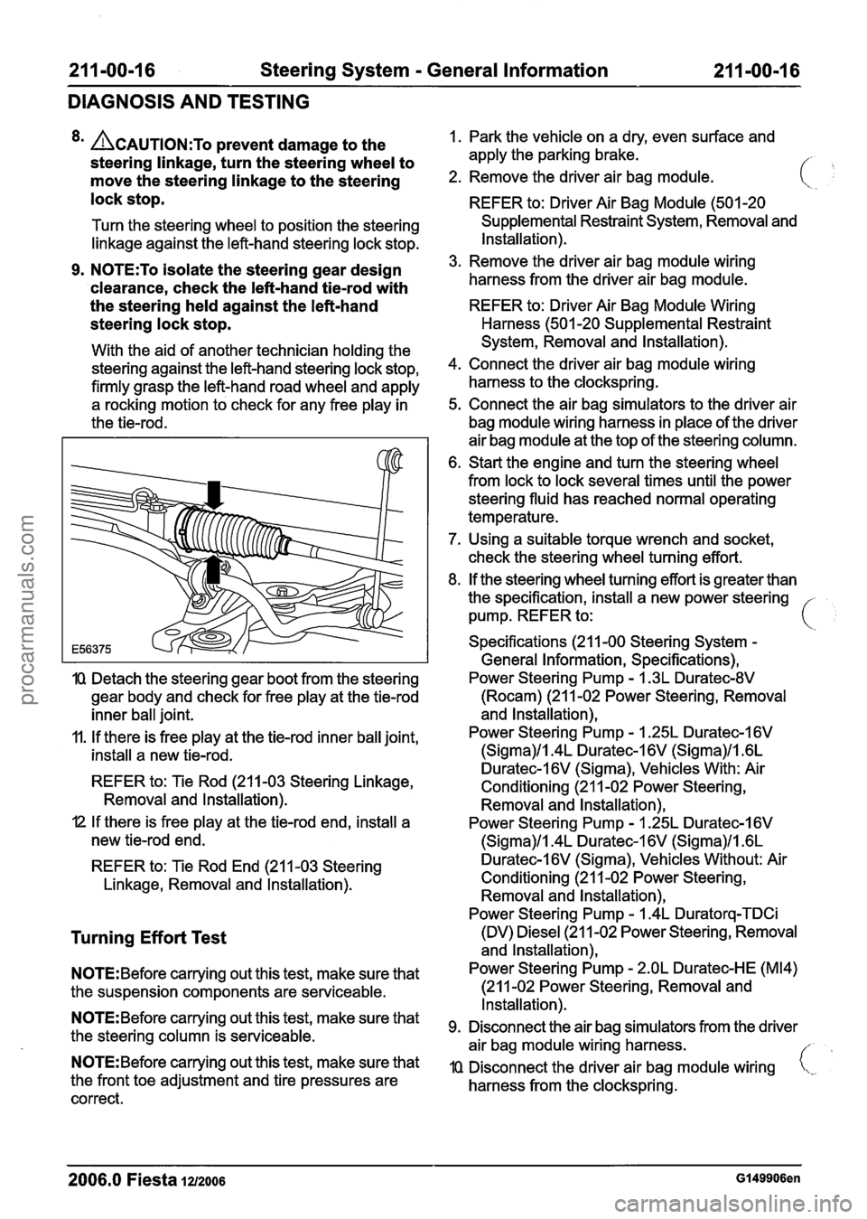
9. N0TE:To isolate the steering gear design
'clearance, check the left-hand
tiemrod with
the steering held against the left-hand
steering lock stop.
With the aid of another technician holding the
steering against the left-hand steering lock stop,
firmly grasp the left-hand road wheel and apply
a rocking motion to check for any free play in
the tie-rod.
IQ Detach the steering gear boot from the steering
gear body and check for free play at the tie-rod
inner ball joint.
11. If there is free play at the tie-rod inner ball joint,
install a new tie-rod.
REFER to: Tie Rod (211-03 Steering Linkage,
Removal and lnstallation).
I2 If there is free play at the tie-rod end, install a
new tie-rod end.
REFER to: Tie Rod End (21 1-03 Steering
Linkage, Removal and lnstallation).
Turning Effort Test
N0TE:Before carrying out this test, make sure that
the suspension components are serviceable.
N0TE:Before carrying out this test, make sure that
the steering column is serviceable.
N0TE:Before carrying out this test, make sure that
the front toe adjustment and tire pressures are
correct. 1.
Park the vehicle on a dry, even surface and
apply the parking brake.
/- ,
2. Remove the driver air bag module.
REFER to: Driver Air Bag Module (501 -20
Supplemental Restraint System, Removal and
Installation).
3. Remove the driver air bag module wiring
harness from the driver air bag module.
REFER to: Driver Air Bag Module Wiring
Harness (501 -20 Supplemental Restraint
System, Removal and Installation).
4. Connect the driver air bag module wiring
harness to the clockspring.
5. Connect the air bag simulators to the driver air
bag module wiring harness in place of the driver
air bag module at the top of the steering column.
6. Start the engine and turn the steering wheel
from lock to lock several times until the power
steering fluid has reached normal operating
temperature.
7. Using a suitable torque wrench and socket,
check the steering wheel turning effort.
8. If the steering wheel turning effort is greater than
the specification, install a new power steering -
pump. REFER to: i
Specifications (21 1-00 Steering System -
General Information, Specifications),
Power Steering Pump
- I .3L Duratec-8V
(Rocam) (21 1-02 Power Steering, Removal
and lnstallation),
Power Steering Pump
- 1.25L Duratec-1 6V
(Sigma)/l.4L Duratec-1 6V (Sigma)/l .6L
Duratec-l6V (Sigma), Vehicles With: Air
Conditioning (21 1-02 Power Steering,
Removal and lnstallation),
Power Steering Pump
- I .25L Duratec-I 6V
(Sigma)/l.4L Duratec-1 6V (Sigma)/l .6L
Duratec-I 6V (Sigma), Vehicles Without: Air
Conditioning (21 1-02 Power Steering, Removal and lnstallation),
Power Steering Pump
- 1.4L Duratorq-TDCi
(DV) Diesel (21 1-02 Power Steering, Removal
and lnstallation),
Power Steering Pump
- 2.OL Duratec-HE (M14)
(21 1-02 Power Steering, Removal and
Installation).
Disconnect the air bag simulators from the driver
air bag module wiring harness.
//
IQ Disconnect the driver air bag module wiring i,,.
harness from the clockspring.
2006.0 Fiesta 1212006 GI 49906en
procarmanuals.com
Page 393 of 1226

211 -02-45 Power Steering 21 1-02-45
REMOVAL AND INSTALLATION
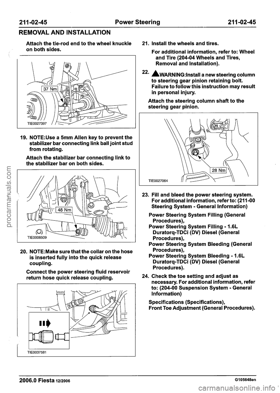
Attach the tie-rod end to the wheel knuckle 21. Install the wheels and tires.
on both sides.
For additional information, refer to: Wheel
and Tire (204-04 Wheels and Tires,
Removal and Installation).
22m AwARNING:~~~~~~~ a new steering column
to steering gear pinion retaining bolt.
Failure to follow this instruction may result
in personal injury.
19.
N0TE:Use a 5mm Allen key to prevent the
stabilizer bar connecting link ball joint stud
from rotating.
Attach the stabilizer bar connecting link to
the stabilizer bar on both sides. Attach
the steering column shaft to the
steering gear pinion.
23. Fill and bleed the power steering system.
For additional information, refer to: (211 -00
Steering System
- General Information)
Power Steering System Filling (General
Procedures),
Power Steering System Filling
- I .6L
Duratorq-TDCi (DV) Diesel (General
Procedures),
Power Steering System Bleeding (General
20.
N0TE:Make sure that the collar on the hose Procedures),
is inserted fully into the quick release Power Steering System
Bleeding - 1.6L
coupling. Duratorq-TDCi (DV) Diesel (General
Procedures).
Connect the power steering fluid reservoir
return hose quick release coupling. 24.
Check the toe setting and adjust as
necessary. For additional information, refer
to: (204-00 Suspension System
- General
Information)
Specifications (Specifications),
Front Toe Adjustment (General Procedures).
2006.0 Fiesta 1212006 GI 05648en
procarmanuals.com