wheels FORD FIESTA 2007 Workshop Manual
[x] Cancel search | Manufacturer: FORD, Model Year: 2007, Model line: FIESTA, Model: FORD FIESTA 2007Pages: 1226, PDF Size: 61.26 MB
Page 3 of 1226
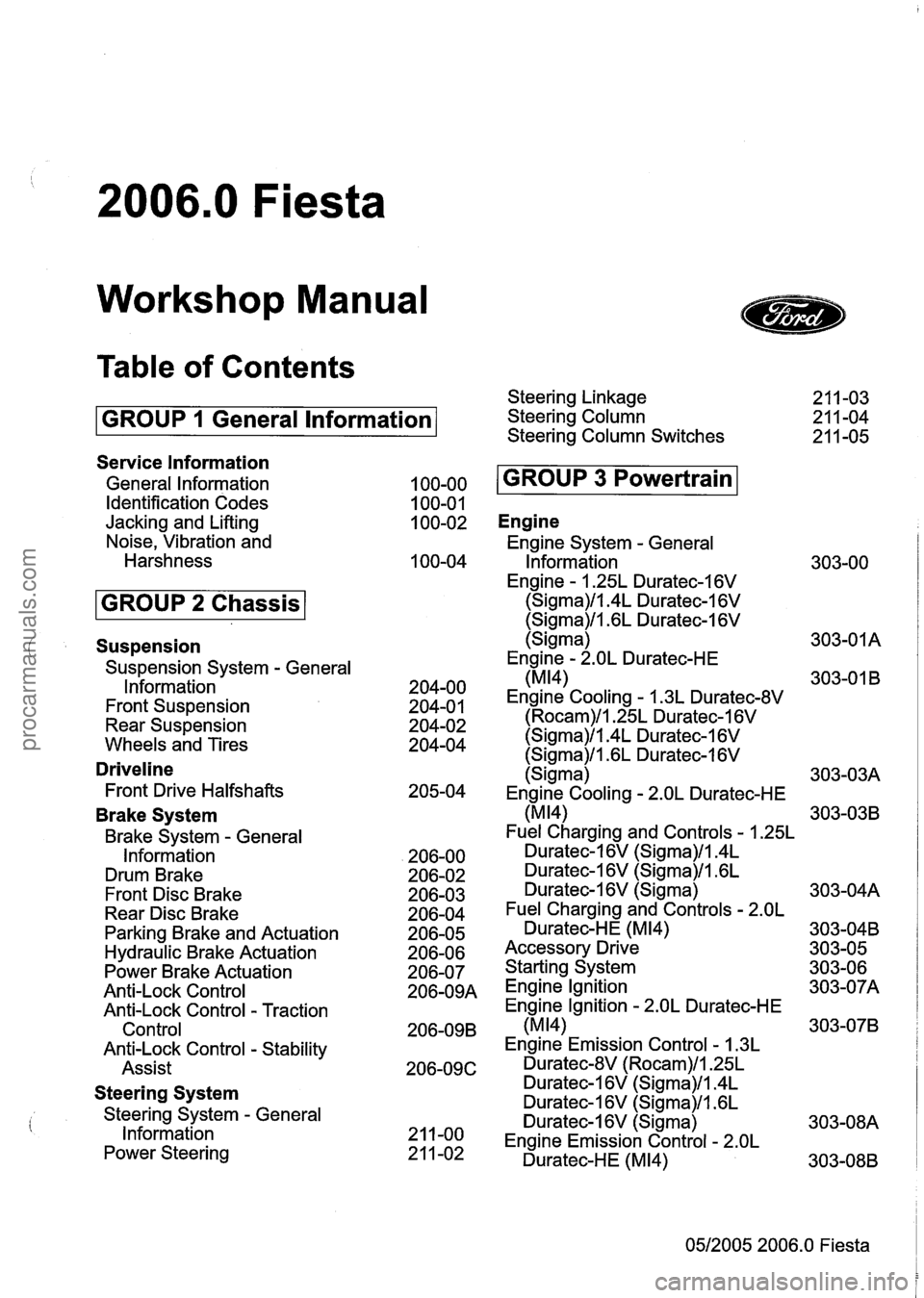
2006.0 Fiesta
Workshop Manual
Table of Contents
GROUP 1 General lnformation
Service lnformation
General lnformation
Identification Codes
Jacking and Lifting
Noise, Vibration and
Harshness
Suspension
Suspension System - General
lnformation
Front Suspension
Rear Suspension
Wheels and Tires
Driveline
Front Drive Halfshafts
Brake System
Brake System - General
Information
Drum Brake
Front Disc Brake
Rear Disc Brake
Parking Brake and Actuation
Hydraulic Brake Actuation
Power Brake Actuation
Anti-Lock Control
Anti-Lock Control
- Traction
Control
Anti-Lock Control
- Stability
Assist
Steering System
Steering System - General
lnformation
Power Steering Steering Linkage
Steering Column
Steering Column Switches
Engine
Engine System - General
lnformation
Engine
- 1.25L Duratec-1 6V
(Sigma)/l.4L Duratec-1 6V
(Sigma)/l.GL Duratec-I 6V
(Sigma)
Engine
- 2.OL Duratec-HE
(MI41
Engine Cooling - 1.3L Duratec-8V
(Rocam)/l.25L Duratec-1 6V
(Sigma)/l.4L Duratec-1 6V
(Sigma)/l .6L Duratec-1 6V
(Sigma)
Engine Cooling
- 2.OL Duratec-HE
(MI41
Fuel Charging and Controls - 1.25L
Duratec-1 6V (Sigma)/l.4L
Duratec-16V (Sigma)/l.GL
Duratec-1 6V (Sigma)
Fuel Charging and Controls
- 2.OL
Duratec-HE (M14)
Accessory Drive
Starting System
Engine lgnition
Engine Ignition
- 2.OL Duratec-HE
(M14)
Engine Emission Control - 1.3L
Duratec-8V (Rocam)/l.25L
Duratec-1 6V (Sigma)/l.4L
Duratec-1 6V (Sigma)/l .6L
Duratec-1
6V (Sigma)
Engine Emission Control
- 2.OL
Duratec-HE (M14)
05/2005 2006.0 Fiesta
procarmanuals.com
Page 9 of 1226
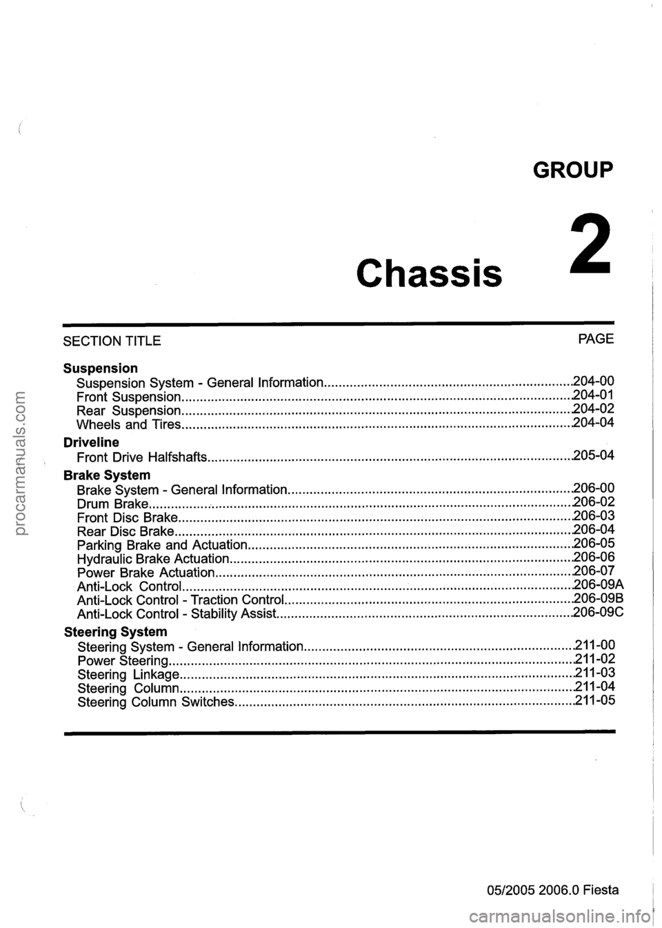
GROUP
Chassis
SECTION TITLE PAGE
Suspension
Suspension
System . General Information .................................................................... 204-00
........................................................................\
................................. Front Suspension .201 4.0
........................................................................\
................................. Rear Suspension .20 4.02
........................................................................\
.................................. Wheels and Tires 204-04
Driveline
Front Drive Halfshafts ........................................................................\
............................ 205-04
' Brake System
Brake System . General Information ........................................................................\
...... 206-00
........................................................................\
.......................................... Drum Brake .20 6.02
Front Disc Brake
........................................................................\
................................... 206-03
Rear Disc Brake
........................................................................\
.................................... 206-04
Parking Brake and Actuation
........................................................................\
................. 206-05
Hydraulic Brake Actuation ........................................................................\
...................... 206-06
Power Brake Actuation
........................................................................\
.......................... 206-07
........................................................................\
.................................. An ti-Lock Control .20 6.09A
Anti-Lock Control . Traction Control ........................................................................\
....... 206-09B
Anti-Lock Control . Stability Assist ........................................................................\
......... 206-09C
Steering System
........................................................................\
. Steering System . General Information .21 1.00
........................................................................\
..................................... Power Steering -21 1-02
........................................................................\
.................................. Steering Linkage -21 1-03
Steering Column
........................................................................\
................................... 21 1-04
Steering Column Switches
........................................................................\
..................... 21 1-05
0512005 2006.0 Fiesta
procarmanuals.com
Page 29 of 1226
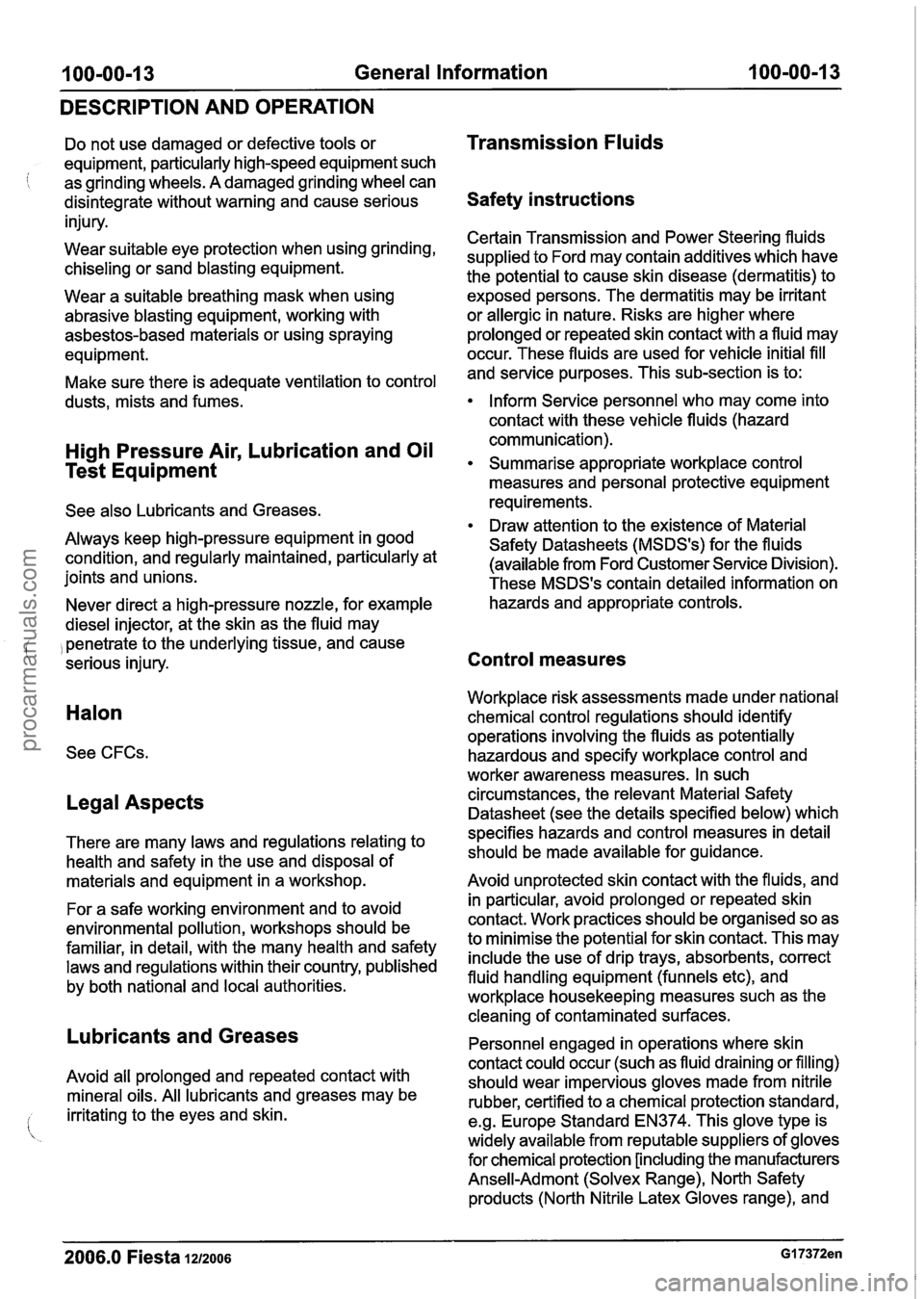
100-00-1 3 General Information 100-00-1 3
DESCRIPTION AND OPERATION
Do not use damaged or defective tools or
equipment, particularly high-speed equipment such
i as grinding wheels. A damaged grinding wheel can
disintegrate without warning and cause serious
injury.
Wear suitable eye protection when using grinding,
chiseling or sand blasting equipment.
Wear a suitable breathing mask when using
abrasive blasting equipment, working with
asbestos-based materials or using spraying
equipment.
Make sure there is adequate ventilation to control
dusts, mists and fumes.
High Pressure Air, Lubrication and Oil
Test Equipment
See also Lubricants and Greases.
Always keep high-pressure equipment in good
condition, and regularly maintained, particularly at
joints and unions.
Never direct a high-pressure nozzle, for example
diesel injector, at the skin as the fluid may
, penetrate to the underlying tissue, and cause
serious injury.
Halon
See CFCs.
Legal Aspects
There are many laws and regulations relating to
health and safety in the use and disposal of
materials and equipment in a workshop.
For a safe working environment and to avoid
environmental pollution, workshops should be
familiar, in detail, with the many health and safety
laws and regulations within their country, published
by both national and local authorities.
Lubricants and Greases
Avoid all prolonged and repeated contact with
mineral oils. All lubricants and greases may be
irritating to the eyes and skin.
'
Transmission Fluids
Safety instructions
Certain Transmission and Power Steering fluids
supplied to Ford may contain additives which have
the potential to cause skin disease (dermatitis) to
exposed persons. The dermatitis may be irritant
or allergic in nature. Risks are higher where
prolonged or repeated skin contact with a fluid may
occur. These fluids are used for vehicle initial
fill
and service purposes. This sub-section is to:
Inform Service personnel who may come into
contact with these vehicle fluids (hazard
communication).
Summarise appropriate workplace control
measures and personal protective equipment
requirements.
Draw attention to the existence of Material
Safety Datasheets (MSDS's) for the fluids
(available from Ford Customer Service Division).
These MSDS's contain detailed information on
hazards and appropriate controls.
Control measures
Workplace risk assessments made under national
chemical control regulations should identify
operations involving the fluids as potentially
hazardous and specify workplace control and
worker awareness measures. In such
circumstances, the relevant Material Safety
Datasheet (see the details specified below) which
specifies hazards and control measures in detail
should be made available for guidance.
Avoid unprotected skin contact with the fluids, and
in particular, avoid prolonged or repeated skin
contact. Work practices should be organised so as
to minimise the potential for skin contact. This may
include the use of drip trays, absorbents, correct
fluid handling equipment (funnels etc), and
workplace housekeeping measures such as the
cleaning of contaminated surfaces.
Personnel engaged in operations where skin
contact could occur (such as fluid draining or filling)
should wear impervious gloves made from
nitrile
rubber, certified to a chemical protection standard,
e.g. Europe Standard EN374. This glove type is
widely available from reputable suppliers of gloves
for chemical protection [including the manufacturers
Ansell-Admont
(Solvex Range), North Safety
products (North
Nitrile Latex Gloves range), and
2006.0 Fiesta 1212006 GI 7372en
procarmanuals.com
Page 35 of 1226
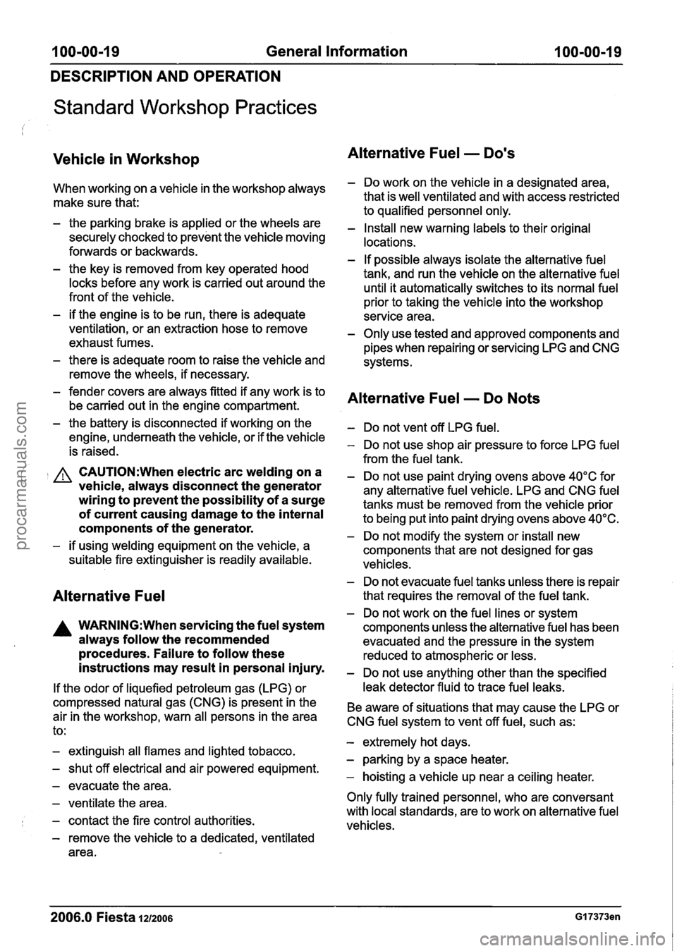
100-00-1 9 General Information 100-00-1 9
DESCRIPTION AND OPERATION
Standard Workshop Practices
Vehicle in Workshop
When working on a vehicle in the workshop always
make sure that:
- the parking brake is applied or the wheels are
securely chocked to prevent the vehicle moving
forwards or backwards.
- the key is removed from key operated hood
locks before any work is carried out around the
front of the vehicle.
- if the engine is to be run, there is adequate
ventilation, or an extraction hose to remove
exhaust fumes.
- there is adequate room to raise the vehicle and
remove the wheels, if necessary.
- fender covers are always fitted if any work is to
be carried out in the engine compartment.
- the battery is disconnected if working on the
engine, underneath the vehicle, or if the vehicle
is raised.
Alternative Fuel - Dons
- Do work on the vehicle in a designated area,
that is well ventilated and with access restricted
to qualified personnel only.
- Install new warning labels to their original
locations.
- If possible always isolate the alternative fuel
tank, and run the vehicle on the alternative fuel
until it automatically switches to its normal fuel
prior to taking the vehicle into the workshop
service area.
- Only use tested and approved components and
pipes when repairing or servicing
LPG and CNG
systems.
Alternative Fuel - Do Nots
- Do not vent off LPG fuel.
- Do not use shop air pressure to force LPG fuel
from the fuel tank.
( A CAUTION:When electric arc welding on a - Do not use paint drying ovens above 40°C for vehicle, always disconnect the generator any alternative fuel vehicle. LPG and CNG fuel wiring to prevent the possibility of a surge tanks must be removed from the vehicle prior of current causing damage to the internal to being put into paint drying ovens above 40°C. components of the generator. - Do not modify the system or install new - if using welding equipment on the vehicle, a
components that are not designed for gas
suitable fire extinguisher is readily available.
vehicles.
Alternative Fuel
A WARNING:When servicing the fuel system
always follow the recommended
procedures. Failure to follow these
instructions may result in personal injury.
If the odor of liquefied petroleum gas (LPG) or
compressed natural gas
(CNG) is present in the
air in the workshop, warn all persons in the area
to:
- extinguish all flames and lighted tobacco.
- shut off electrical and air powered equipment.
- evacuate the area.
- ventilate the area.
- contact the fire control authorities.
- remove the vehicle to a dedicated, ventilated
area.
- Do not evacuate fuel tanks unless there is repair
that requires the removal of the fuel tank.
- Do not work on the fuel lines or system
components unless the alternative fuel has been
evacuated and the pressure in the system
reduced to atmospheric or less.
- Do not use anything other than the specified
leak detector fluid to trace fuel leaks.
Be aware of situations that may cause the
LPG or I
CNG fuel system to vent off fuel, such as: I
- extremely hot days.
- parking by a space heater.
- hoisting a vehicle up near a ceiling heater.
Only fully trained personnel, who are conversant
with local standards, are to work on alternative fuel
vehicles.
2006.0 Fiesta 1212006 GI 7373en
procarmanuals.com
Page 36 of 1226
100-00-20 General Information 100-00-20
DESCRIPTION AND OPERATION
Towing the Vehicle
an instance, the discharged battery must
be recharged immediately after jump
A WARN1NG:When the vehicle is being starting
to avoid permanent damage. ( towed, the ignition switch must be in - Always make sure that the jumper cables are
position ll (steering lock released and adequate for the task. Heavy duty cables must
warning lamps illuminated). Only then will be used.
the turn signal lamps, horn and - Always make sure that the slave battery is of stop lamps be operational. Failure to follow the same voltage as the vehicle battery. The these instructions may result in personal batteries must be connected in parallel. injury. - Always make sure that switched electric circuits
N0TE:The removable towing eye (if equipped),
are switched off before connecting jumper
has a left-hand thread and must be fully tightened cables. This reduces the risk of arcing occurring
before towing can commence.
when the final connection is made.
When towing is necessary, the vehicle towing eyes
should be used. The rope must be securely
fastened to the towing eyes and must also be
attached to the other vehicle such that the rope will
not foul the bodywork.
When a vehicle with automatic transmission is
towed, the gear selector must be in position
N
(Neutral). Never tow a vehicle with automatic
transmission at a speed greater than 30 mph (50
kmlh) or for a distance greater than 30 miles (50
km). If it is necessary to tow the vehicle a greater
distance, the drive wheels must be lifted clear off
the ground.
I A WARN1NG:Make sure that the ends of the Alternatively the vehicle can be transported on a jumper cables do not touch each other or low loader or a trailer. ground against the vehicle body at any
time while the cables are attached to the
Connectin a Slave Battery Using
73
battery. A fully charged battery, if shorted
Jumper Ca les through jumper cables, can discharge at
a rate well above
I000 amps causing
A WARNING:H the slave battery has recently violent arcing
and very rapid heating of the
been charged and is gassing, cover the jumper cables and
terminals, and can even
vent plugs or covers with a damp cloth to cause
the battery to explode. Failure to
reduce the risk of explosion should arcing follow
these instructions may result in
occur when connecting the jumper cables. personal injury.
Failure to follow these instructions may
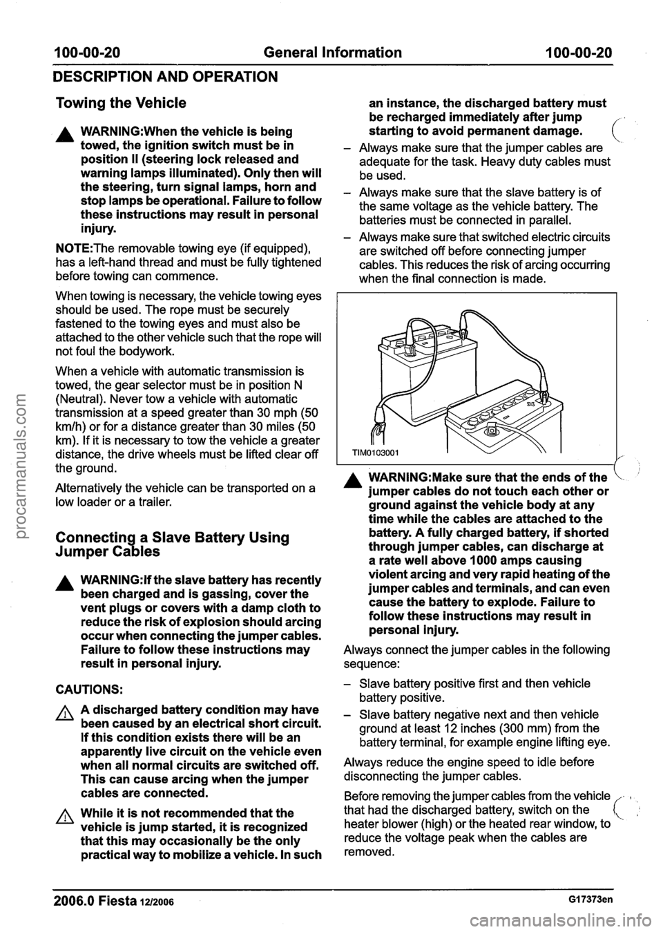
Always connect the jumper cables in the following
result in personal injury. sequence:
CAUTIONS:
A A discharged battery condition may have
been caused by an electrical short circuit.
If this condition exists there will be an
apparently live circuit on the vehicle even
when all normal circuits are switched off.
This can cause arcing when the jumper
cables are connected.
A While it is not recommended that the
vehicle is jump started,
it is recognized
that this may occasionally be the only
practical way to mobilize a vehicle. In such
- Slave battery positive first and then vehicle
battery positive.
- Slave battery negative next and then vehicle
ground at least
12 inches (300 mm) from the
battery terminal, for example engine lifting eye.
Always reduce the engine speed to idle before
disconnecting the jumper cables.
Before removing the jumper cables from the vehicle
-
heater blower (high) or the heated rear window, to
that
had the discharged battery, switch on the
reduce the voltage peak when the cables are
removed.
2006.0 Fiesta 1~12006 GI 7373en
procarmanuals.com
Page 46 of 1226

Identification Codes
DESCRIPTION AND OPERATION
I Item 1 Details I
Indicates the maximum combined mass of vehicle
and trailer or caravan.
ltem 5: Maximum permissible front axle mass Maximum permissible loading on the front wheels
of the vehicle.
ltem
6: Maximum permissible rear axle mass Maximum permissible loading on the rear wheels
of the vehicle.
I Per meter I
ltem 7: Smoke Value (Diesel only)
Number
I JC3 I %door van (Fiesta) I
Smoke Value
ltem
8 Model Body or Type
I JD3 I %door (Fiesta) I
Code
I JHI I 5-door (Fiesta) I
Model Body or Type
I JU2 I 5-door (Fusion) I
ltem 10: Door Combination
ltem
9: Model
Type
ltem 11: Exhaust Emission Level Codes
f Code
Code
-
Model Type
Door Combination
-
ltem 12: Body Color Codes
Code
S 7 Exhaust Emissions
2000 EEC (Stage
Ill)
Stage IV requirements
Code B
I J I Tonic
Body Color
Diamond White
D
G Panther Black
Performance Blue
I Q I Oyster Silver I
K
L
M
2006.0 Fiesta 1212006 G413286en
Colorado Red
Deep Rosso Red Magnum Grey
([
procarmanuals.com
Page 61 of 1226
100-04-5 Noise, Vibration and Harshness 100-04-5
DIAGNOSIS AND TESTING
Noise Conditions
Gear noise is typically a howling or whining due
to gear damage or incorrect bearing preload. It
can occur at various speeds and driving
conditions, or it can be continuous.
Chuckle is a particular rattling noise that sounds
like a stick against the spokes of a spinning
bicycle wheel. It occurs while decelerating from
64
kmlh (40 mph) and can usually be heard all
the way to a stop. The frequency varies with
vehicle speed.
Knock is very similar to chuckle, though it may
be louder and occurs on acceleration or
deceleration. The
teardown will disclose what
has to be corrected.
Clicking, popping or grinding noises may be caused
by the following:
worn, damaged or incorrectly installed wheel
bearing, suspension or brake component.
Check and rule out tires, exhaust and trim items
before disassembling the transmission to diagnose
and correct gear noise.
The noises described under Road Test usually
( have specific causes that can be diagnosed by
observation as the unit is disassembled. The initial
clues are the type of noise heard on the road test
and driving conditions.
Vibration Conditions
Vibration at highway speeds may be caused by
the following:
out-of-balance front or rear wheels.
out-of-round tires.
Shudder or vibration during acceleration may be
caused by the following:
damaged powertrainldrivetrain mounts.
excessively high constant velocity (CV) joint
operating angles caused by incorrect ride height.
Check ride height, verify correct spring rate and
check items under inoperative conditions.
Road Test
I A gear-driven unit will produce a certain amount
of noise. Some noise is acceptable and may be
audible at certain speeds or under various driving conditions,
as on a newly paved asphalt road. The
slight noise is in no way detrimental and must be
considered normal.
The road test and customer interview (if available)
provide information needed to identify the condition
-
and give direction to the correct starting point for
diagnosis.
1. Make notes throughout the diagnosis routine.
Make sure to write down even the smallest bit
of information, because it may turn out to be the
most important.
2. Do not touch anything until a road test and a
thorough visual inspection of the vehicle have been carried out. Leave the tire pressures and
vehicle load just where they were when the
condition was first observed. Adjusting tire
pressures, vehicle load or making other
adjustments may reduce the
condition(s)
intensity to a point where it cannot be identified
clearly. It may also inject something new into
the system, preventing correct diagnosis.
3. Make a visual inspection as part of the
preliminary diagnosis routine, writing down
anything that does not look right. Note tire
pressures, but do not adjust them yet. Note
leaking fluids, loose nuts and bolts, or bright
spots where components may be rubbing
against each other. Check the load space for
unusual loads.
4. Road test the vehicle and define the condition
by reproducing it several times during the road
test.
5. Carry out the Road Test Quick Checks as soon
as the condition is reproduced. This will identify
the correct diagnostic procedure. Carry out the
Road Test Quick Checks more than once to
verify they are providing a valid result.
Remember, the Road Test Quick Checks may
not tell where the concern is, but they will tell
where it is not.
Road Test Quick Checks
1. 24-80 kmlh (1 5-50 mph): with light acceleration,
a moaning noise is heard and possibly a
vibration felt in the front floor panel. It is usually
worse at a particular engine speed and at a
particular throttle setting during acceleration at
that speed. It may also produce a moaning
sound, depending on what component is
causing it. REFER to Tip-in Moan in the
Driveline Noise and Vibration Symptom Chart.
2006.0 Fiesta 1212006 G37349en
procarmanuals.com
Page 62 of 1226
100-04-6 Noise, Vibration and Harshness 100-04-6
DIAGNOSIS AND TESTING
2. AccelerationIDeceleration: With slow
acceleration and deceleration, a shake is
sometimes noticed in the steering
wheellcolumn,
seats, front floor panel, front door trim panel or
front end sheet metal. It is a low frequency
vibration (around
9-1 5 cycles per second). It
may or may not be increased by applying the
brakes lightly. REFER to
Idle
BoomIShakeNibration in the Driveline Noise
and Vibration Symptom Chart.
High Speed: A vibration is felt in the front floor
panel or seats with no visible shake, but with
an accompanying sound or rumble, buzz, hum,
drone or booming noise. Coast with the clutch
pedal depressed (manual transmission) or shift
control selector lever in "N" (NEUTRAL)
(automatic transmission) and engine idling. If
vibration is still evident, it may be related to
wheels, tires, front brake discs, wheel hubs or
front wheel bearings. REFER to Shake and
Vibration While Driving in the Driveline Noise
and Vibration Symptom Chart.
4. Engine rpm Sensitive: A vibration is felt
whenever the engine reaches a particular rpm.
It will disappear in neutral coasts. The vibration
can be duplicated by operating the engine at
the problem rpm while the vehicle is stationary.
It can be caused by any component, from the
accessory drive belt to the clutch or torque
converter which turns at engine speed when the
vehicle is stopped. REFER to Shake and
Vibration While Driving in the Driveline Noise
and Vibration Symptom Chart.
5. Noise and Vibration While Turning: Clicking,
popping or grinding noises may be due to the
following:
worn, damaged or incorrectly installed front
wheel bearing.
damaged
powertrainldrivetrain mounts.
Road Conditions
An experienced technician will always establish a
route that will be used for all NVH diagnosis road
tests. The road selected should be reasonably
smooth, level and free of undulations (unless a
particular condition needs to be identified). A
smooth asphalt road that allows driving over a
range of speeds is best. Gravel or bumpy roads
are unsuitable because of the additional road noise produced.
Once the route is established and
consistently used, the road noise variable is
eliminated from the test results.
N0TE:Some concerns may be apparent only on
smooth asphalt roads.
If a customer complains of a noise or vibration on
a particular road and only on a particular road, the
source of the concern may be the road surface. If
possible, try to test the vehicle on the same type
of road.
Vehicle Preparation
Carry out a thorough visual inspection of the
vehicle before carrying out the road test. Note
anything which is unusual. Do not repair or adjust
any condition until the road test is carried out,
unless the vehicle is inoperative or the condition
could pose a hazard to the technician. After
verifying that the condition has been corrected,
make sure all components removed have been
installed.
Power Steering Conditions
c !
Check for the noise in the following conditions to
verify the customer concern.
Check for the noise in several temperature
conditions.
Is the noise from when the vehicle was new?
Can the noise be repeated constantly or is it
random?
Check the condition of the vehicle age, mileage
and service record.
Interview the customer to find the operating
condition in which the noise will occur. Test the
vehicle based on the
detail(s) from the customer
interview.
Follow the power steering operation noise
condition tables below, to find which condition
the noise will occur.
Power Steering Operation Noise Check
Step 1 : Check for NVH concerns from non-steering
components, which may sound like noises coming
from the steering system.
I:. ':
2006.0 Fiesta 121zoo6 G37349en
procarmanuals.com
Page 76 of 1226

100-04-20 Noise, Vibration and Harshness 100-04-20
DIAGNOSIS AND TESTING
TEST CONDITIONS DETAILSIRESULTSIACTIONS
C4: CHECK THE POWERTRAINIDRIVETRAIN MOUNTS
Carry out the powertrainldrivetrain mount neut-
ralizing procedure
Are the powertrainldrivetrain mounts OK?
+ Yes
Vehicle condition corrected. ROAD TEST as
necessary.
+ No
INSTALL new powertrainldrivetrain mounts
as necessary. ROAD TEST as necessary.
PINPOINT TEST D
: WHEEL END VIBRATION ANALYSIS
TEST CONDITIONS
DETAILSIRESU LTSIACTIONS
Dl: INSPECT THE WHEELS AND TIRES
Inspect the wheels and tires.
REFER to: Wheels and Tires (204-04 Wheels
and Tires, Diagnosis and Testing).
Are the wheels and tires OK?
+ Yes
GO to D2.
+ No
INSTALL new wheels or tires as necessary.
REFER to: Wheel and Tire (204-04 Wheels
and Tires, Removal and Installation).
ROAD TEST as necessary.
2006.0 Fiesta 1212006 G37349en
procarmanuals.com
Page 77 of 1226

100-04-21 Noise, Vibration and Harshness 100-04-21
DIAGNOSIS AND TESTING
TEST CONDITIONS DETAILSIRESULTSIACTIONS
I D2: INSPECT THE WHEEL BEARINGS
lnspect the wheel bearings.
REFER to: Wheel Bearing Inspection (204-00
Suspension System
- General Information,
General Procedures).
Are the wheel bearings OK?
+ Yes
GO to D3.
+ No
INSTALL new wheel bearings as necessary.
REFER to:
Wheel Bearing (204-01 Front Suspension,
Removal and lnstallation),
Wheel Bearing
- 2.OL Duratorq-DiITDDi (Puma)
Diesel12.0L Duratorq-TDCi (Puma) Diesel,
Vehicles With: 5-Speed Automatic Transaxle
(5F31 J) (204-01 Front Suspension, Removal
and lnstallation),
Wheel Hub (204-02 Rear Suspension, Removal
and lnstallation). ROAD TEST as necessary.
I D3: INSPECT THE WHEEL AND TIRE RUNOUT I
lnspect the wheel and tire runout.
Is the wheel and tire runout OK?
+ Yes
Balance the wheels and tires. Refer to the
wheel balance equipment manufacturer's
instructions. ROAD TEST as necessary.
+ No
INSTALL new wheels or tires as necessary.
REFER to: Wheel and Tire (204-04 Wheels
and Tires, Removal and Installation).
ROAD TEST as necessary.
2006.0 Fiesta 1212006 G37349en
procarmanuals.com