warning FORD FLEX 2014 1.G Owners Manual
[x] Cancel search | Manufacturer: FORD, Model Year: 2014, Model line: FLEX, Model: FORD FLEX 2014 1.GPages: 554, PDF Size: 8.04 MB
Page 255 of 554
Remember to account for the trailer tongue weight as part of your
vehicle load when calculating the total vehicle weight.
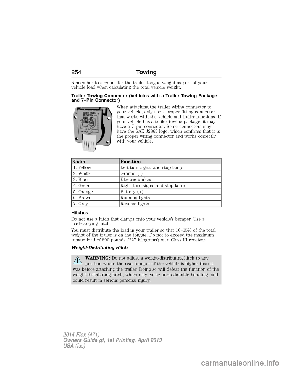
Trailer Towing Connector (Vehicles with a Trailer Towing Package
and 7–Pin Connector)
When attaching the trailer wiring connector to
your vehicle, only use a proper fitting connector
that works with the vehicle and trailer functions. If
your vehicle has a trailer towing package, it may
have a 7–pin connector. Some connectors may
have the SAE J2863 logo, which confirms that it is
the proper wiring connector and works correctly
with your vehicle.
Color Function
1. Yellow Left turn signal and stop lamp
2. White Ground (-)
3. Blue Electric brakes
4. Green Right turn signal and stop lamp
5. Orange Battery (+)
6. Brown Running lights
7. Grey Reverse lights
Hitches
Do not use a hitch that clamps onto your vehicle’s bumper. Use a
load-carrying hitch.
You must distribute the load in your trailer so that 10–15% of the total
weight of the trailer is on the tongue. Do not to exceed the maximum
tongue load of 500 pounds (227 kilograms) on a Class III receiver.
Weight-Distributing Hitch
WARNING:Do not adjust a weight-distributing hitch to any
position where the rear bumper of the vehicle is higher than it
was before attaching the trailer. Doing so will defeat the function of the
weight-distributing hitch, which may cause unpredictable handling, and
could result in serious personal injury.
254Towing
2014 Flex(471)
Owners Guide gf, 1st Printing, April 2013
USA(fus)
Page 256 of 554
When hooking-up a trailer using a weight-distributing hitch, always use
the following procedure:
1. Park your vehicle, without the trailer, on a level surface.
2. Measure the height of the top of your vehicle’s front wheel opening
on the fender. This is H1.
3. Attach the trailer to your vehicle without the weight-distributing bars
connected.
4. Measure the height of the top of your vehicle’s front wheel opening
on the fender a second time. This is H2.
5. Install and adjust the tension in the weight distributing bars so that
the height of the front fender is approximately halfway between H1
and H2.
6. Check that the trailer is level. If not level, adjust the ball height
accordingly and repeat Steps 3–6.
Safety Chains
Note:Never attach safety chains to the bumper.
Always connect the safety chains to the hook retainers of your vehicle
hitch.
To connect the safety chains, cross them under the trailer tongue and
allow enough slack for turning tight corners. Do not allow the chains to
drag on the ground.
Trailer Brakes
WARNING:Do not connect a trailer’s hydraulic brake system
directly to your vehicle’s brake system. Your vehicle may not have
enough braking power and your chances of having a collision greatly
increase.
Electric brakes and manual, automatic or surge-type trailer brakes are
safe if you install them properly and adjust them to the manufacturer’s
specifications. The trailer brakes must meet local and federal regulations.
The rating for the tow vehicle’s braking system operation is at
the gross vehicle weight rating, not the gross combined weight
rating.
Separate functioning brake systems are required for safe control
of towed vehicles and trailers weighing more than 1500 pounds
(680 kilograms) when loaded.
Towing255
2014 Flex(471)
Owners Guide gf, 1st Printing, April 2013
USA(fus)
Page 257 of 554
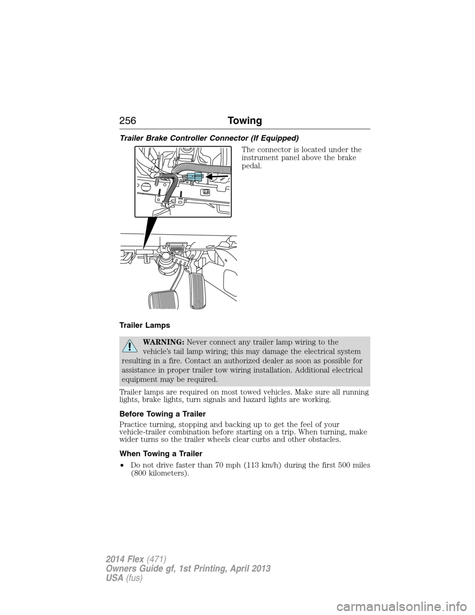
Trailer Brake Controller Connector (If Equipped)
The connector is located under the
instrument panel above the brake
pedal.
Trailer Lamps
WARNING:Never connect any trailer lamp wiring to the
vehicle’s tail lamp wiring; this may damage the electrical system
resulting in a fire. Contact an authorized dealer as soon as possible for
assistance in proper trailer tow wiring installation. Additional electrical
equipment may be required.
Trailer lamps are required on most towed vehicles. Make sure all running
lights, brake lights, turn signals and hazard lights are working.
Before Towing a Trailer
Practice turning, stopping and backing up to get the feel of your
vehicle-trailer combination before starting on a trip. When turning, make
wider turns so the trailer wheels clear curbs and other obstacles.
When Towing a Trailer
•Do not drive faster than 70 mph (113 km/h) during the first 500 miles
(800 kilometers).
256Towing
2014 Flex(471)
Owners Guide gf, 1st Printing, April 2013
USA(fus)
Page 263 of 554
•Add particular accessories to your vehicle (e.g.; bug deflectors,
rollbars or light bars, running boards, ski racks).
•Drive with the wheels out of alignment.
DRIVING THROUGH WATER
WARNING:Drive through water in an emergency only, and not
as part of normal driving.
WARNING:Engine damage can occur if water enters the air
filter.
Note:Driving through deep water may allow water into the transmission
or air intake and can cause internal vehicle damage or cause it to stall.
Note:Once through the water, always dry the brakes by moving your
vehicle slowly while applying light pressure on the brake pedal.
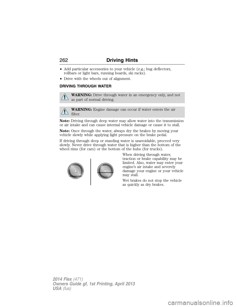
If driving through deep or standing water is unavoidable, proceed very
slowly. Never drive through water that is higher than the bottom of the
wheel rims (for cars) or the bottom of the hubs (for trucks).
When driving through water,
traction or brake capability may be
limited. Also, water may enter your
engine’s air intake and severely
damage your engine or your vehicle
may stall.
Wet brakes do not stop the vehicle
as quickly as dry brakes.
262Driving Hints
2014 Flex(471)
Owners Guide gf, 1st Printing, April 2013
USA(fus)
Page 264 of 554
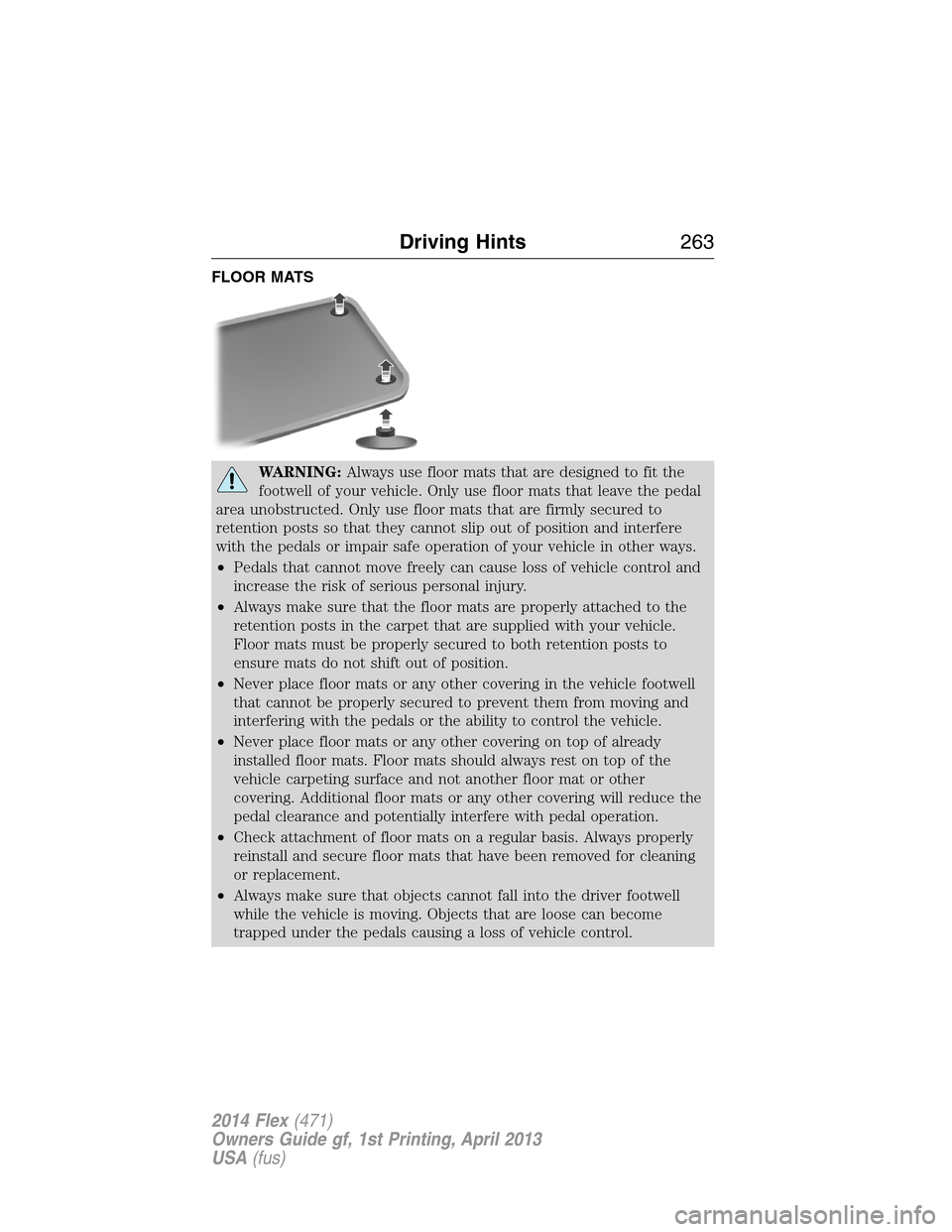
FLOOR MATS
WARNING:Always use floor mats that are designed to fit the
footwell of your vehicle. Only use floor mats that leave the pedal
area unobstructed. Only use floor mats that are firmly secured to
retention posts so that they cannot slip out of position and interfere
with the pedals or impair safe operation of your vehicle in other ways.
•Pedals that cannot move freely can cause loss of vehicle control and
increase the risk of serious personal injury.
•Always make sure that the floor mats are properly attached to the
retention posts in the carpet that are supplied with your vehicle.
Floor mats must be properly secured to both retention posts to
ensure mats do not shift out of position.
•Never place floor mats or any other covering in the vehicle footwell
that cannot be properly secured to prevent them from moving and
interfering with the pedals or the ability to control the vehicle.
•Never place floor mats or any other covering on top of already
installed floor mats. Floor mats should always rest on top of the
vehicle carpeting surface and not another floor mat or other
covering. Additional floor mats or any other covering will reduce the
pedal clearance and potentially interfere with pedal operation.
•Check attachment of floor mats on a regular basis. Always properly
reinstall and secure floor mats that have been removed for cleaning
or replacement.
•Always make sure that objects cannot fall into the driver footwell
while the vehicle is moving. Objects that are loose can become
trapped under the pedals causing a loss of vehicle control.
Driving Hints263
2014 Flex(471)
Owners Guide gf, 1st Printing, April 2013
USA(fus)
Page 265 of 554
WARNING(Continued)
•Failure to properly follow floor mat installation or attachment
instructions can potentially cause interference with pedal operation
causing loss of control of vehicle.
•To install floor mats, position the floor mat so that the eyelet is over
the retention post and press down to lock in.
•To remove the floor mat, reverse the installation procedure.
264Driving Hints
2014 Flex(471)
Owners Guide gf, 1st Printing, April 2013
USA(fus)
Page 267 of 554
U.S. Ford vehicle customers who require Roadside Assistance, call
1-800-241-3673.
If you need to arrange roadside assistance for yourself, Ford Motor
Company will reimburse a reasonable amount for towing to the nearest
dealership within 35 miles (56 kilometers). To obtain reimbursement
information, U.S. Ford vehicle customers call 1-800-241-3673. Customers
will be asked to submit their original receipts.
Vehicles Sold in Canada: Getting Roadside Assistance
Canadian customers who require roadside assistance, call
1–800–665–2006.
Vehicles Sold in Canada: Using Roadside Assistance
For your convenience, you may complete the roadside assistance
identification card found in the centerfold of this warranty guide and
retain for future reference.
Canadian roadside coverage and benefits may differ from the U.S.
coverage. If you require more information, please refer to the coverage
section of your warranty guide, call us in Canada at 1-800-665-2006, or
visit our website at www.ford.ca.
HAZARD WARNING FLASHERS
The hazard flasher control is located on the instrument panel
by the radio. Use it when your vehicle is disabled and is
creating a safety hazard for other motorists.
•Press the flasher control and all front and rear direction signals will
flash.
•Press the flasher control again to turn them off.
Note:With extended use, the flashers may run down your 12–volt
battery.
FUEL CUT-OFF SWITCH
WARNING:Failure to inspect and if necessary repair fuel leaks
after a collision may increase the risk of fire and serious injury.
Ford Motor Company recommends that the fuel system be inspected by
an authorized dealer after any collision.
In the event of a moderate to severe collision, this vehicle is equipped
with a fuel pump shut-off feature that stops the flow of fuel to the
engine. Not every impact will cause a shut-off.
266Roadside Emergencies
2014 Flex(471)
Owners Guide gf, 1st Printing, April 2013
USA(fus)
Page 268 of 554
Should your vehicle shut off after a collision, you may restart your
vehicle by doing the following:
1. Turn the ignition off and wait approximately 10 seconds.
2. Turn the ignition on.
3. Repeat steps 1 and 2 to re-enable the fuel pump.
JUMP-STARTING THE VEHICLE
WARNING:The gases around the battery can explode if exposed
to flames, sparks, or lit cigarettes. An explosion could result in
injury or vehicle damage.
WARNING:Batteries contain sulfuric acid which can burn skin,
eyes and clothing, if contacted.
Do not attempt to push-start your automatic transmission vehicle.
Automatic transmissions do not have push-start capability. Attempting to
push-start a vehicle with an automatic transmission may cause
transmission damage.
When the battery is disconnected or a new battery is installed, the
automatic transmission must relearn its shift strategy. As a result, the
transmission may exhibit a combination of firm and soft shifts. This
operation is considered normal and will not affect function or durability
of the transmission. Over time, the adaptive learning process will fully
update transmission operation.
Preparing Your Vehicle
Note:Use only a 12–volt supply to start your vehicle.
Note:Do not disconnect the battery of the disabled vehicle as this could
damage the vehicle’s electrical system.
1. Park the booster vehicle close to the hood of the disabled vehicle
making sure the two vehicles do not touch. Set the parking brake on
both vehicles and stay clear of the engine cooling fan and other moving
parts.
2. Check all battery terminals. Remove the positive terminal cover (if
equipped) and any excessive corrosion before you attach the battery
cables. Ensure that vent caps are tight and level.
3. Turn the heater fan on in both vehicles to protect from any electrical
surges. Turn all other accessories off.
Roadside Emergencies267
2014 Flex(471)
Owners Guide gf, 1st Printing, April 2013
USA(fus)
Page 269 of 554
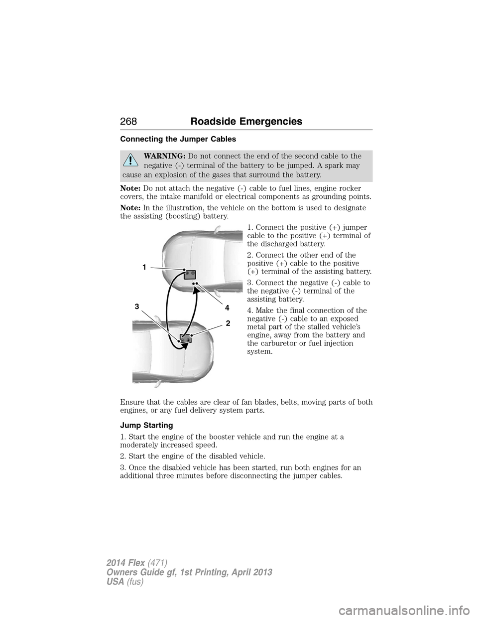
Connecting the Jumper Cables
WARNING:Do not connect the end of the second cable to the
negative (-) terminal of the battery to be jumped. A spark may
cause an explosion of the gases that surround the battery.
Note:Do not attach the negative (-) cable to fuel lines, engine rocker
covers, the intake manifold or electrical components as grounding points.
Note:In the illustration, the vehicle on the bottom is used to designate
the assisting (boosting) battery.
1. Connect the positive (+) jumper
cable to the positive (+) terminal of
the discharged battery.
2. Connect the other end of the
positive (+) cable to the positive
(+) terminal of the assisting battery.
3. Connect the negative (-) cable to
the negative (-) terminal of the
assisting battery.
4. Make the final connection of the
negative (-) cable to an exposed
metal part of the stalled vehicle’s
engine, away from the battery and
the carburetor or fuel injection
system.
Ensure that the cables are clear of fan blades, belts, moving parts of both
engines, or any fuel delivery system parts.
Jump Starting
1. Start the engine of the booster vehicle and run the engine at a
moderately increased speed.
2. Start the engine of the disabled vehicle.
3. Once the disabled vehicle has been started, run both engines for an
additional three minutes before disconnecting the jumper cables.
4
2
1
3
268Roadside Emergencies
2014 Flex(471)
Owners Guide gf, 1st Printing, April 2013
USA(fus)
Page 279 of 554
CHANGING A FUSE
Fuses
WARNING:Always replace a fuse with one that has the
specified amperage rating. Using a fuse with a higher amperage
rating can cause severe wire damage and could start a fire.
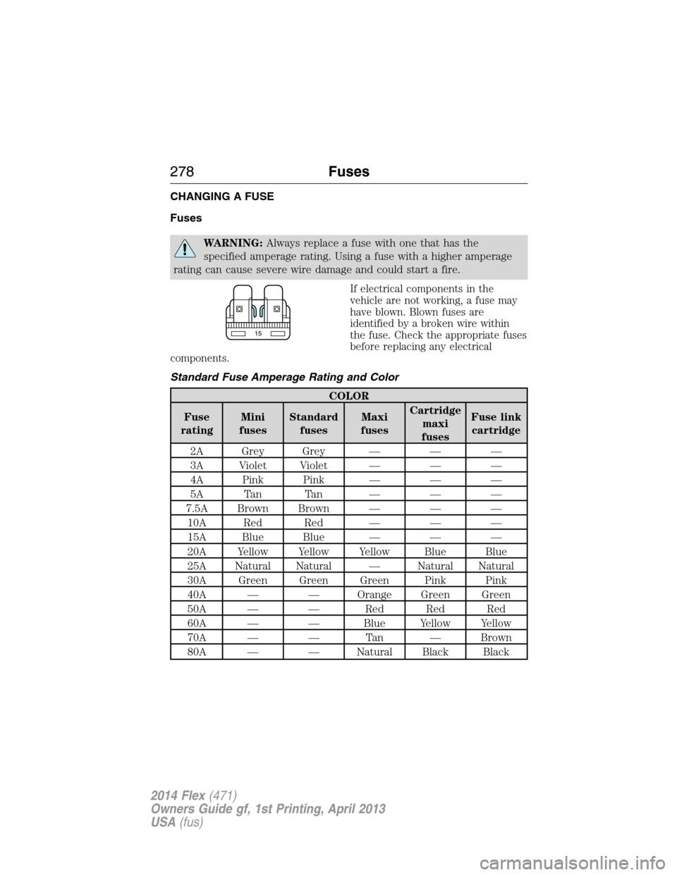
If electrical components in the
vehicle are not working, a fuse may
have blown. Blown fuses are
identified by a broken wire within
the fuse. Check the appropriate fuses
before replacing any electrical
components.
Standard Fuse Amperage Rating and Color
COLOR
Fuse
ratingMini
fusesStandard
fusesMaxi
fusesCartridge
maxi
fusesFuse link
cartridge
2A Grey Grey — — —
3A Violet Violet — — —
4A Pink Pink — — —
5A Tan Tan — — —
7.5A Brown Brown — — —
10A Red Red — — —
15A Blue Blue — — —
20A Yellow Yellow Yellow Blue Blue
25A Natural Natural — Natural Natural
30A Green Green Green Pink Pink
40A — — Orange Green Green
50A — — Red Red Red
60A — — Blue Yellow Yellow
70A — — Tan — Brown
80A — — Natural Black Black
15
278Fuses
2014 Flex(471)
Owners Guide gf, 1st Printing, April 2013
USA(fus)