battery FORD FOCUS 2003 1.G Owners Manual
[x] Cancel search | Manufacturer: FORD, Model Year: 2003, Model line: FOCUS, Model: FORD FOCUS 2003 1.GPages: 216, PDF Size: 4.15 MB
Page 3 of 216
Maintenance and Specifications 161
Engine compartment 163
Engine oil 166
Battery 170
Fuel information 178
Part numbers 196
Refill capacities 196
Lubricant specifications 198
Accessories 205
Index 208
All rights reserved. Reproduction by any means, electronic or mechanical
including photocopying, recording or by any information storage and retrieval
system or translation in whole or part is not permitted without written
authorization from Ford Motor Company. Ford may change the contents without
notice and without incurring obligation.
Copyright © 2002 Ford Motor Company
Table of Contents
3
Page 9 of 216
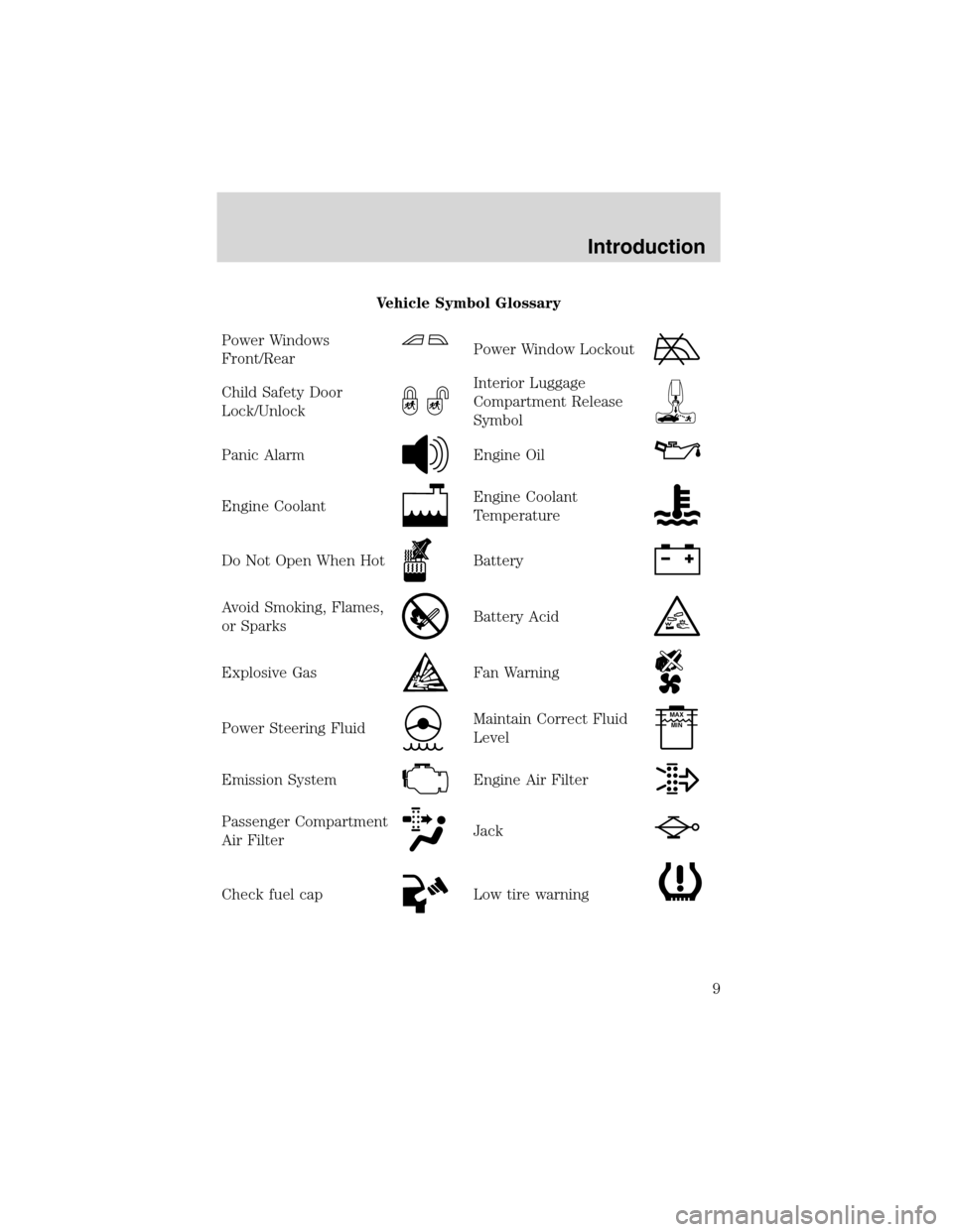
Vehicle Symbol Glossary
Power Windows
Front/Rear
Power Window Lockout
Child Safety Door
Lock/UnlockInterior Luggage
Compartment Release
Symbol
Panic AlarmEngine Oil
Engine CoolantEngine Coolant
Temperature
Do Not Open When HotBattery
Avoid Smoking, Flames,
or SparksBattery Acid
Explosive GasFan Warning
Power Steering FluidMaintain Correct Fluid
LevelMAX
MIN
Emission SystemEngine Air Filter
Passenger Compartment
Air FilterJack
Check fuel capLow tire warning
Introduction
9
Page 12 of 216
Driving a vehicle with the brake system warning light on is
dangerous. A significant decrease in braking performance may
occur. It will take you longer to stop the vehicle. Have the vehicle
checked by your dealer immediately.
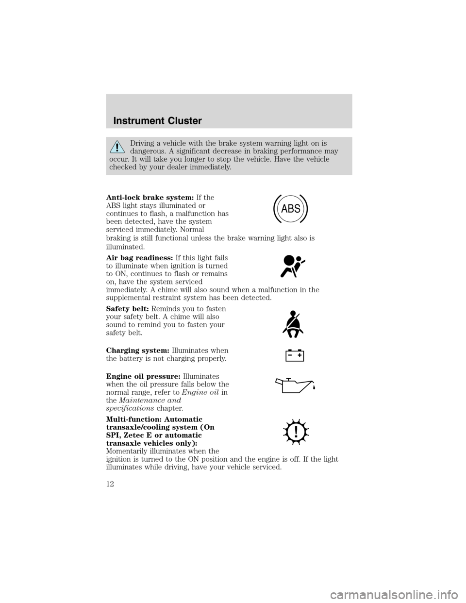
Anti-lock brake system:If the
ABS light stays illuminated or
continues to flash, a malfunction has
been detected, have the system
serviced immediately. Normal
braking is still functional unless the brake warning light also is
illuminated.
Air bag readiness:If this light fails
to illuminate when ignition is turned
to ON, continues to flash or remains
on, have the system serviced
immediately. A chime will also sound when a malfunction in the
supplemental restraint system has been detected.
Safety belt:Reminds you to fasten
your safety belt. A chime will also
sound to remind you to fasten your
safety belt.
Charging system:Illuminates when
the battery is not charging properly.
Engine oil pressure:Illuminates
when the oil pressure falls below the
normal range, refer toEngine oilin
theMaintenance and
specificationschapter.
Multi-function: Automatic
transaxle/cooling system (On
SPI, Zetec E or automatic
transaxle vehicles only):
Momentarily illuminates when the
ignition is turned to the ON position and the engine is off. If the light
illuminates while driving, have your vehicle serviced.
ABS
Instrument Cluster
12
Page 41 of 216
3. Open the hood.
4. Remove the battery cover.
5. Remove the headlamp bulb cover by releasing the four snap hooks
(two top and two bottom).
Note:On the left headlamp, pull the bulb cover approximately 1 inch
rearward and then slide it out until the vertical aiming adjuster is
accessible.
6. Turn on the low beam to illuminate the wall or screen. On the wall or
screen you will observe an area of high intensity light. If the left side of
each light pattern is not at the reference line, the beam needs to be
adjusted.
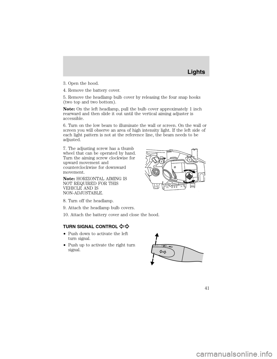
7. The adjusting screw has a thumb
wheel that can be operated by hand.
Turn the aiming screw clockwise for
upward movement and
counterclockwise for downward
movement.
Note:HORIZONTAL AIMING IS
NOT REQUIRED FOR THIS
VEHICLE AND IS
NON-ADJUSTABLE.
8. Turn off the headlamp.
9. Attach the headlamp bulb covers.
10. Attach the battery cover and close the hood.
TURN SIGNAL CONTROL
•Push down to activate the left
turn signal.
•Push up to activate the right turn
signal.
Lights
41
Page 66 of 216
Locking the doors
•Pressand release to lock all the doors.Note:the parking lamps
will flash once.
If any of the doors are not properly closed the horn will make two quick
chirps.
This process will also activate the vehicle’s anti-theft system (if
equipped). For more information on arming the anti-theft system, refer
toSecurilock passive anti-theft systemin this chapter.
Opening the luggage compartment
Pressonce to open the luggage compartment.Note:This feature
will only operate with the ignition in the OFF or ACC positions.
•Ensure that the trunk is closed and latched before driving your
vehicle. Failure to properly latch the trunk may cause objects to fall
out or block the driver’s rear view.
Sounding a panic alarm
Press
to activate the alarm. Press again or turn the ignition to ACC
or ON to deactivate.
Note:The panic alarm will only operate when the ignition is in the OFF
position.
Replacing the battery
The remote entry transmitter uses one coin type three-volt lithium
battery CR2032 or equivalent. The typical operating range for your
remote entry transmitter is approximately 10 meters (33 feet). A
decrease in the operating range could be caused by:
•weather conditions,
•nearby radio towers,
•structures around the vehicle and
•other vehicles parked next to the vehicle.
Locks and Security
66
Page 67 of 216
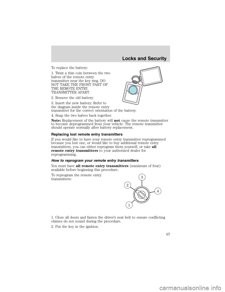
To replace the battery:
1. Twist a thin coin between the two
halves of the remote entry
transmitter near the key ring. DO
NOT TAKE THE FRONT PART OF
THE REMOTE ENTRY
TRANSMITTER APART.
2. Remove the old battery.
3. Insert the new battery. Refer to
the diagram inside the remote entry
transmitter for the correct orientation of the battery.
4. Snap the two halves back together.
Note:Replacement of the battery willnotcause the remote transmitter
to become deprogrammed from your vehicle. The remote transmitter
should operate normally after battery replacement.
Replacing lost remote entry transmitters
If you would like to have your remote entry transmitter reprogrammed
because you lost one, or would like to buy additional remote entry
transmitters, you can either reprogram them yourself, or takeall
remote entry transmittersto your authorized dealer for
reprogramming.
How to reprogram your remote entry transmitters
You must haveall remote entry transmitters(maximum of four)
available before beginning this procedure.
To reprogram the remote entry
transmitters:
1. Close all doors and fasten the driver’s seat belt to ensure conflicting
chimes do not sound during the procedure.
2. Put the key in the ignition.
Locks and Security
67
Page 74 of 216
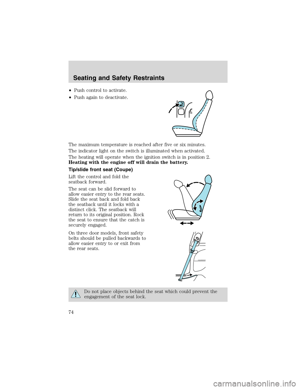
•Push control to activate.
•Push again to deactivate.
The maximum temperature is reached after five or six minutes.
The indicator light on the switch is illuminated when activated.
The heating will operate when the ignition switch is in position 2.
Heating with the engine off will drain the battery.
Tip/slide front seat (Coupe)
Lift the control and fold the
seatback forward.
The seat can be slid forward to
allow easier entry to the rear seats.
Slide the seat back and fold back
the seatback until it locks with a
distinct click. The seatback will
return to its original position. Rock
the seat to ensure that the catch is
securely engaged.
On three door models, front safety
belts should be pulled backwards to
allow easier entry to or exit from
the rear seats.
Do not place objects behind the seat which could prevent the
engagement of the seat lock.
Seating and Safety Restraints
74
Page 126 of 216
U.S. Ford or Mercury vehicle customers who require roadside assistance,
call 1–800–241–3673; Lincoln vehicle customers call 1–800–521–4140.
Canadian customers who require roadside assistance, call
1–800–665–2006.
If you need to arrange roadside assistance for yourself, Ford Motor
Company will reimburse a reasonable amount. To obtain reimbursement
information, U.S. Ford or Mercury vehicles customers call
1-800-241-3673; Lincoln vehicle customers call 1–800–521–4140.
Canadian customers who need to obtain reimbursement information, call
1–800–665–2006.
ROADSIDE COVERAGE BEYOND BASIC WARRANTY
In the United States, you may purchase additional roadside assistance
coverage beyond this period through the Ford Auto Club by contacting
your Ford or Lincoln Mercury dealer.
Similarly in Canada, for uninterrupted Roadside Assistance coverage, you
may purchase extended coverage prior to your Basic Warranty’s Roadside
Assistance expiring. For more information and enrollment, contact
1–877–294–2582 or visit our website at www.ford.ca.
HAZARD FLASHER CONTROL
The hazard flasher is located on the
instrument panel by the radio. The
hazard flashers will operate when
the ignition is off.
Push in the flasher control and all front and rear direction signals will
flash. Press the flasher control again to turn them off. Use it when your
vehicle is disabled and is creating a safety hazard for other motorists.
Note:With extended use, the flasher may run down your battery.
FUEL PUMP SHUT-OFF SWITCH
FUEL
RESET
This device stops the electric fuel pump from sending fuel to the engine
when your vehicle has had a substantial jolt.
After an accident, if the engine cranks but does not start, this switch
may have been activated.
Roadside Emergencies
126
Page 130 of 216
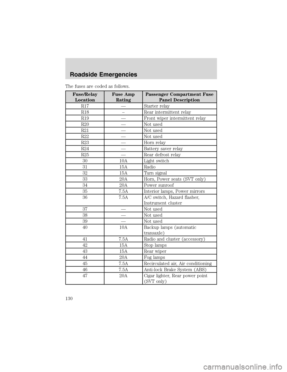
The fuses are coded as follows.
Fuse/Relay
LocationFuse Amp
RatingPassenger Compartment Fuse
Panel Description
R17—Starter relay
R18–Rear intermittent relay
R19—Front wiper intermittent relay
R20—Not used
R21—Not used
R22—Not used
R23—Horn relay
R24—Battery saver relay
R25—Rear defrost relay
30 10A Light switch
31 15A Radio
32 15A Turn signal
33 20A Horn, Power seats (SVT only)
34 20A Power sunroof
35 7.5A Interior lamps, Power mirrors
36 7.5A A/C switch, Hazard flasher,
Instrument cluster
37—Not used
38—Not used
39—Not used
40 10A Backup lamps (automatic
transaxle)
41 7.5A Radio and cluster (accessory)
42 15A Stop lamps
43 15A Rear wiper
44 20A Fog lamps
45 7.5A Recirculated air, Air conditioning
46 7.5A Anti-lock Brake System (ABS)
47 20A Cigar lighter, Rear power point
(SVT only)
Roadside Emergencies
130
Page 131 of 216
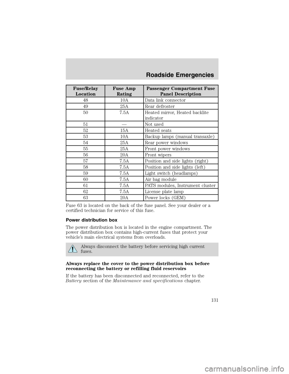
Fuse/Relay
LocationFuse Amp
RatingPassenger Compartment Fuse
Panel Description
48 10A Data link connector
49 25A Rear defroster
50 7.5A Heated mirror, Heated backlite
indicator
51—Not used
52 15A Heated seats
53 10A Backup lamps (manual transaxle)
54 25A Rear power windows
55 25A Front power windows
56 20A Front wipers
57 7.5A Position and side lights (right)
58 7.5A Position and side lights (left)
59 7.5A Light switch (headlamps)
60 7.5A Air bag module
61 7.5A PATS modules, Instrument cluster
62 7.5A License plate lamp
63 20A Power locks (GEM)
Fuse 63 is located on the back of the fuse panel. See your dealer or a
certified technician for service of this fuse.
Power distribution box
The power distribution box is located in the engine compartment. The
power distribution box contains high-current fuses that protect your
vehicle’s main electrical systems from overloads.
Always disconnect the battery before servicing high current
fuses.
Always replace the cover to the power distribution box before
reconnecting the battery or refilling fluid reservoirs
If the battery has been disconnected and reconnected, refer to the
Batterysection of theMaintenance and specificationschapter.
Roadside Emergencies
131