FORD FOCUS 2005 1.G Owners Manual
Manufacturer: FORD, Model Year: 2005, Model line: FOCUS, Model: FORD FOCUS 2005 1.GPages: 224, PDF Size: 3.39 MB
Page 131 of 224
Fuse/Relay
LocationFuse Amp
RatingPassenger Compartment Fuse
Panel Description
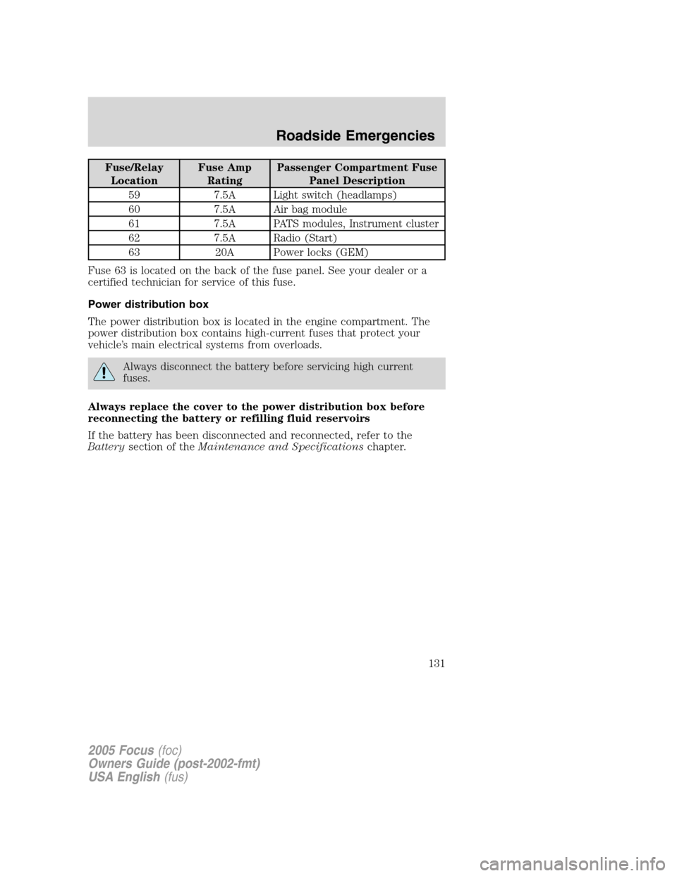
59 7.5A Light switch (headlamps)
60 7.5A Air bag module
61 7.5A PATS modules, Instrument cluster
62 7.5A Radio (Start)
63 20A Power locks (GEM)
Fuse 63 is located on the back of the fuse panel. See your dealer or a
certified technician for service of this fuse.
Power distribution box
The power distribution box is located in the engine compartment. The
power distribution box contains high-current fuses that protect your
vehicle’s main electrical systems from overloads.
Always disconnect the battery before servicing high current
fuses.
Always replace the cover to the power distribution box before
reconnecting the battery or refilling fluid reservoirs
If the battery has been disconnected and reconnected, refer to the
Batterysection of theMaintenance and Specificationschapter.
2005 Focus(foc)
Owners Guide (post-2002-fmt)
USA English(fus)
Roadside Emergencies
131
Page 132 of 224
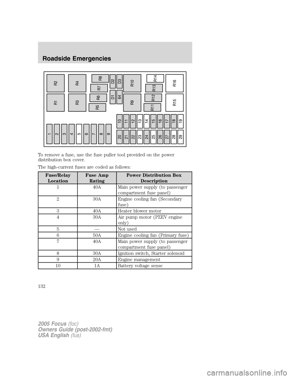
To remove a fuse, use the fuse puller tool provided on the power
distribution box cover.
The high-current fuses are coded as follows:
Fuse/Relay
LocationFuse Amp
RatingPower Distribution Box
Description
1 40A Main power supply (to passenger
compartment fuse panel)
2 30A Engine cooling fan (Secondary
fuse)
3 40A Heater blower motor
4 30A Air pump motor (PZEV engine
only)
5—Not used
6 50A Engine cooling fan (Primary fuse)
7 40A Main power supply (to passenger
compartment fuse panel)
8 30A Ignition switch, Starter solenoid
9 20A Engine management
10 1A Battery voltage sense
2005 Focus(foc)
Owners Guide (post-2002-fmt)
USA English(fus)
Roadside Emergencies
132
Page 133 of 224
Fuse/Relay
LocationFuse Amp
RatingPower Distribution Box
Description
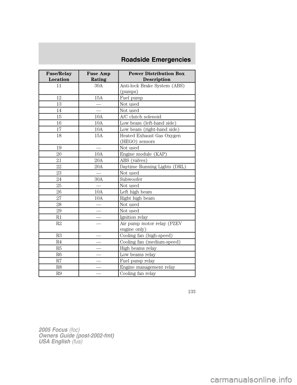
11 30A Anti-lock Brake System (ABS)
(pumps)
12 15A Fuel pump
13—Not used
14—Not used
15 10A A/C clutch solenoid
16 10A Low beam (left-hand side)
17 10A Low beam (right-hand side)
18 15A Heated Exhaust Gas Oxygen
(HEGO) sensors
19—Not used
20 10A Engine module (KAP)
21 20A ABS (valves)
22 20A Daytime Running Lights (DRL)
23—Not used
24 30A Subwoofer
25—Not used
26 10A Left high beam
27 10A Right high beam
28—Not used
29—Not used
R1—Ignition relay
R2—Air pump motor relay (PZEV
engine only)
R3—Cooling fan (high-speed)
R4—Cooling fan (medium-speed)
R5—High beams relay
R6—Low beams relay
R7—Fuel pump relay
R8—Engine management relay
R9—Cooling fan relay
2005 Focus(foc)
Owners Guide (post-2002-fmt)
USA English(fus)
Roadside Emergencies
133
Page 134 of 224
Fuse/Relay
LocationFuse Amp
RatingPower Distribution Box
Description
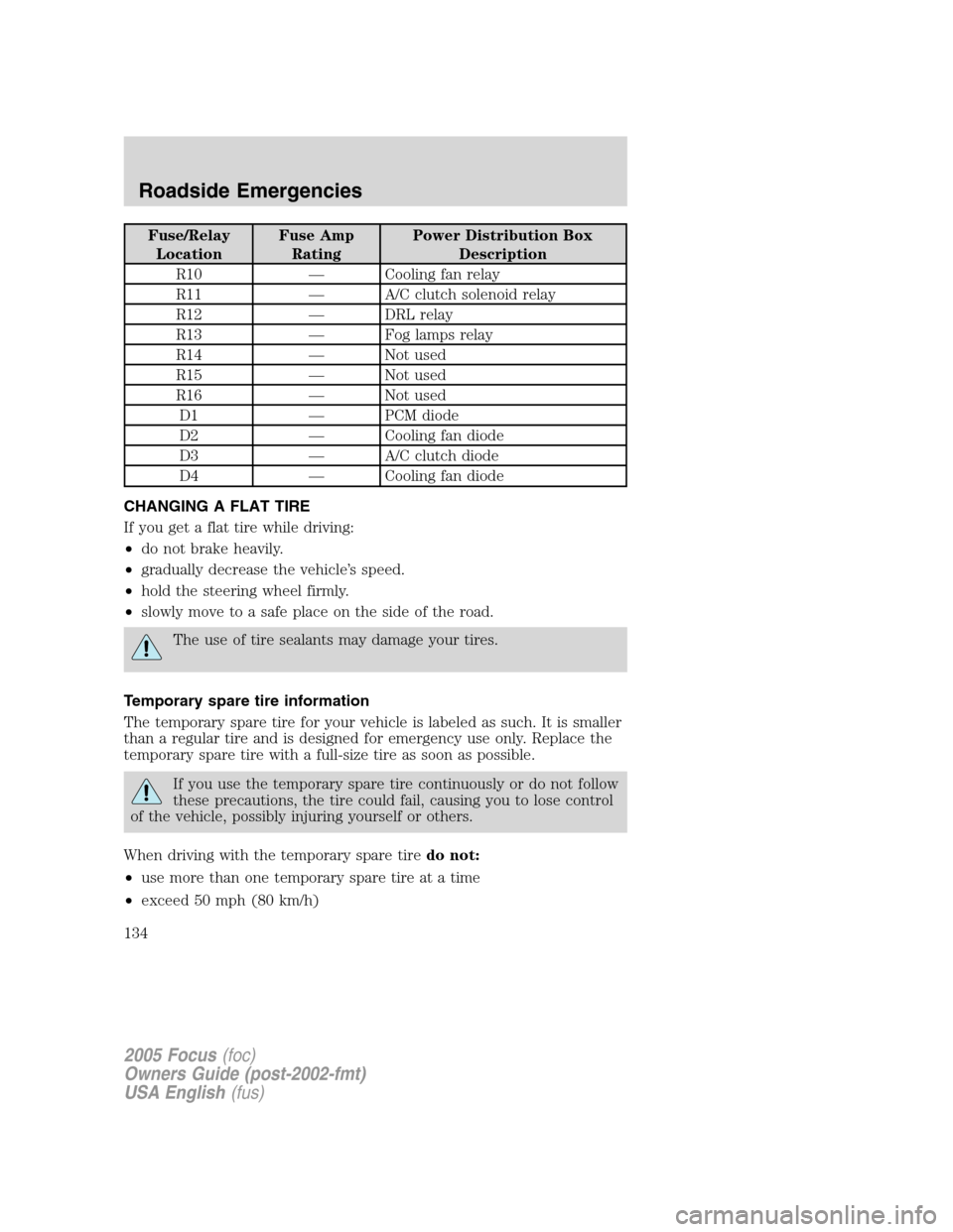
R10—Cooling fan relay
R11—A/C clutch solenoid relay
R12—DRL relay
R13—Fog lamps relay
R14—Not used
R15—Not used
R16—Not used
D1—PCM diode
D2—Cooling fan diode
D3—A/C clutch diode
D4—Cooling fan diode
CHANGING A FLAT TIRE
If you get a flat tire while driving:
•do not brake heavily.
•gradually decrease the vehicle’s speed.
•hold the steering wheel firmly.
•slowly move to a safe place on the side of the road.
The use of tire sealants may damage your tires.
Temporary spare tire information
The temporary spare tire for your vehicle is labeled as such. It is smaller
than a regular tire and is designed for emergency use only. Replace the
temporary spare tire with a full-size tire as soon as possible.
If you use the temporary spare tire continuously or do not follow
these precautions, the tire could fail, causing you to lose control
of the vehicle, possibly injuring yourself or others.
When driving with the temporary spare tiredo not:
•use more than one temporary spare tire at a time
•exceed 50 mph (80 km/h)
2005 Focus(foc)
Owners Guide (post-2002-fmt)
USA English(fus)
Roadside Emergencies
134
Page 135 of 224
•load the vehicle beyond maximum vehicle load rating listed on the
Safety Compliance Label
•tow a trailer
•use tire chains
•drive through an automatic car wash, because of the vehicle’s reduced
ground clearance
•try to repair the temporary spare tire or remove it from its wheel
•use the wheel for any other type of vehicle
Use of a temporary spare tire at any one wheel location can lead to
impairment of the following:
•handling, stability and braking performance
•comfort and noise
•ground clearance and parking at curbs
•Winter driving capability
Dissimilar spare tire/wheel information
Failure to follow these guidelines could result in an increased
risk of loss of vehicle control, injury or death.
Your vehicle may be equipped with a dissimilar spare tire/wheel. A
dissimilar spare tire/wheel is defined as a spare tire and/or wheel that is
different in brand, size or appearance from the road tires and wheels. If
you have a dissimilar spare tire/wheel, then it is intended for temporary
use only. This means that if you need to use it, you should replace it as
soon as possible with a road tire/wheel that is the same size and type as
the road tires and wheels that were originally provided by Ford. If the
dissimilar spare tire or wheel is damaged, it should be replaced rather
than repaired.
When driving with the dissimilar spare tire/wheel,do not:
•Exceed 70 mph (113 km/h)
•Use more than one dissimilar spare tire/wheel at a time
•Use commercial car washing equipment
•Use snow chains on the end of the vehicle with the dissimilar spare
tire/wheel
2005 Focus(foc)
Owners Guide (post-2002-fmt)
USA English(fus)
Roadside Emergencies
135
Page 136 of 224
The usage of a dissimilar spare tire/wheel can lead to impairment of the
following:
•Handling, stability and braking performance
•Comfort and noise
•Ground clearance and parking at curbs
•Winter weather driving capability
•Wet weather driving capability
•All-Wheel Driving Capability (if applicable)
•Load Leveling Adjustment (if applicable)
When driving with the dissimilar spare tire/wheel additional caution
should be given to:
•Towing a trailer
•Driving vehicles equipped with a camper body
•Driving vehicles with a load on the cargo rack
Drive cautiously when using a dissimilar spare tire/wheel and seek
service as soon as possible.
Tire change procedure
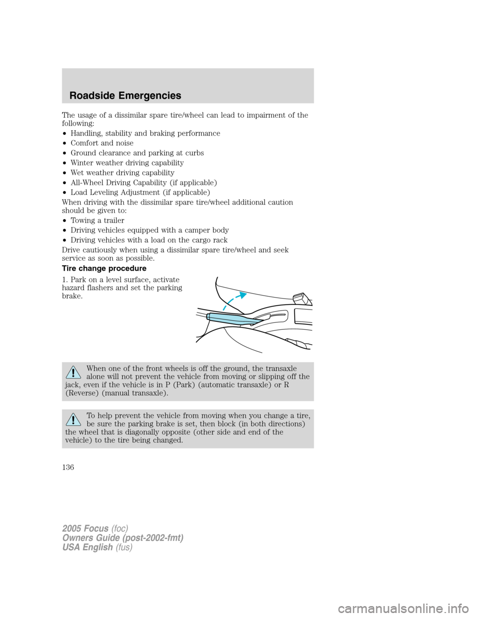
1. Park on a level surface, activate
hazard flashers and set the parking
brake.
When one of the front wheels is off the ground, the transaxle
alone will not prevent the vehicle from moving or slipping off the
jack, even if the vehicle is in P (Park) (automatic transaxle) or R
(Reverse) (manual transaxle).
To help prevent the vehicle from moving when you change a tire,
be sure the parking brake is set, then block (in both directions)
the wheel that is diagonally opposite (other side and end of the
vehicle) to the tire being changed.
2005 Focus(foc)
Owners Guide (post-2002-fmt)
USA English(fus)
Roadside Emergencies
136
Page 137 of 224
If the vehicle slips off the jack, you or someone else could be
seriously injured.
2. Place gearshift lever in P (Park) (automatic transaxle) or R (Reverse)
(manual transaxle), turn engine OFF, and block the diagonally opposite
wheel.
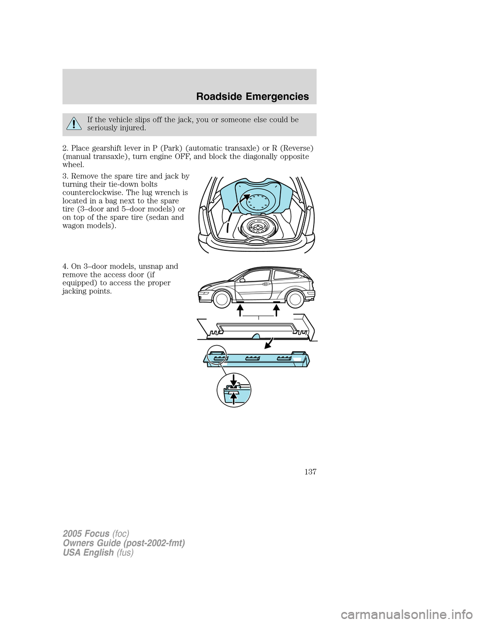
3. Remove the spare tire and jack by
turning their tie-down bolts
counterclockwise. The lug wrench is
located in a bag next to the spare
tire (3–door and 5–door models) or
on top of the spare tire (sedan and
wagon models).
4. On 3–door models, unsnap and
remove the access door (if
equipped) to access the proper
jacking points.
2005 Focus(foc)
Owners Guide (post-2002-fmt)
USA English(fus)
Roadside Emergencies
137
Page 138 of 224
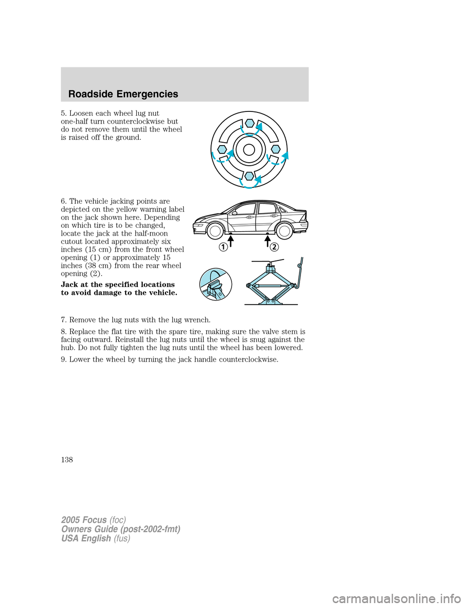
5. Loosen each wheel lug nut
one-half turn counterclockwise but
do not remove them until the wheel
is raised off the ground.
6. The vehicle jacking points are
depicted on the yellow warning label
on the jack shown here. Depending
on which tire is to be changed,
locate the jack at the half-moon
cutout located approximately six
inches (15 cm) from the front wheel
opening (1) or approximately 15
inches (38 cm) from the rear wheel
opening (2).
Jack at the specified locations
to avoid damage to the vehicle.
7. Remove the lug nuts with the lug wrench.
8. Replace the flat tire with the spare tire, making sure the valve stem is
facing outward. Reinstall the lug nuts until the wheel is snug against the
hub. Do not fully tighten the lug nuts until the wheel has been lowered.
9. Lower the wheel by turning the jack handle counterclockwise.
2005 Focus(foc)
Owners Guide (post-2002-fmt)
USA English(fus)
Roadside Emergencies
138
Page 139 of 224
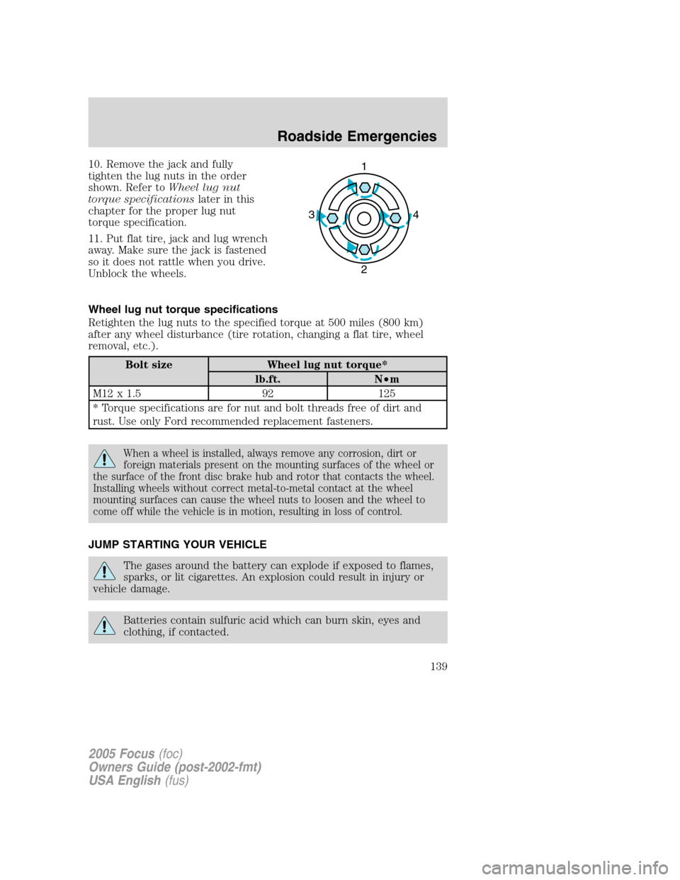
10. Remove the jack and fully
tighten the lug nuts in the order
shown. Refer toWheel lug nut
torque specificationslater in this
chapter for the proper lug nut
torque specification.
11. Put flat tire, jack and lug wrench
away. Make sure the jack is fastened
so it does not rattle when you drive.
Unblock the wheels.
Wheel lug nut torque specifications
Retighten the lug nuts to the specified torque at 500 miles (800 km)
after any wheel disturbance (tire rotation, changing a flat tire, wheel
removal, etc.).
Bolt size Wheel lug nut torque*
lb.ft. N•m
M12 x 1.5 92 125
* Torque specifications are for nut and bolt threads free of dirt and
rust. Use only Ford recommended replacement fasteners.
When a wheel is installed, always remove any corrosion, dirt or
foreign materials present on the mounting surfaces of the wheel or
the surface of the front disc brake hub and rotor that contacts the wheel.
Installing wheels without correct metal-to-metal contact at the wheel
mounting surfaces can cause the wheel nuts to loosen and the wheel to
come off while the vehicle is in motion, resulting in loss of control.
JUMP STARTING YOUR VEHICLE
The gases around the battery can explode if exposed to flames,
sparks, or lit cigarettes. An explosion could result in injury or
vehicle damage.
Batteries contain sulfuric acid which can burn skin, eyes and
clothing, if contacted.
1
4 3
2
2005 Focus(foc)
Owners Guide (post-2002-fmt)
USA English(fus)
Roadside Emergencies
139
Page 140 of 224
Do not attempt to push-start your vehicle. Automatic
transmissions do not have push-start capability; doing so may
damage the catalytic converter.
Preparing your vehicle
When the battery is disconnected or a new battery is installed, the
transmission must relearn its shift strategy. As a result, the transmission
may have firm and/or soft shifts. This operation is considered normal and
will not affect function or durability of the transmission. Over time, the
adaptive learning process will fully update transmission operation.
1.Use only a 12–volt supply to start your vehicle.
2. Do not disconnect the battery of the disabled vehicle as this could
damage the vehicle’s electrical system.
3. Park the booster vehicle close to the hood of the disabled vehicle
making sure the two vehiclesdo nottouch. Set the parking brake on
both vehicles and stay clear of the engine cooling fan and other moving
parts.
4. Check all battery terminals and remove any excessive corrosion before
you attach the battery cables. Ensure that vent caps are tight and level.
5. Turn the heater fan on in both vehicles to protect any electrical
surges. Turn all other accessories off.
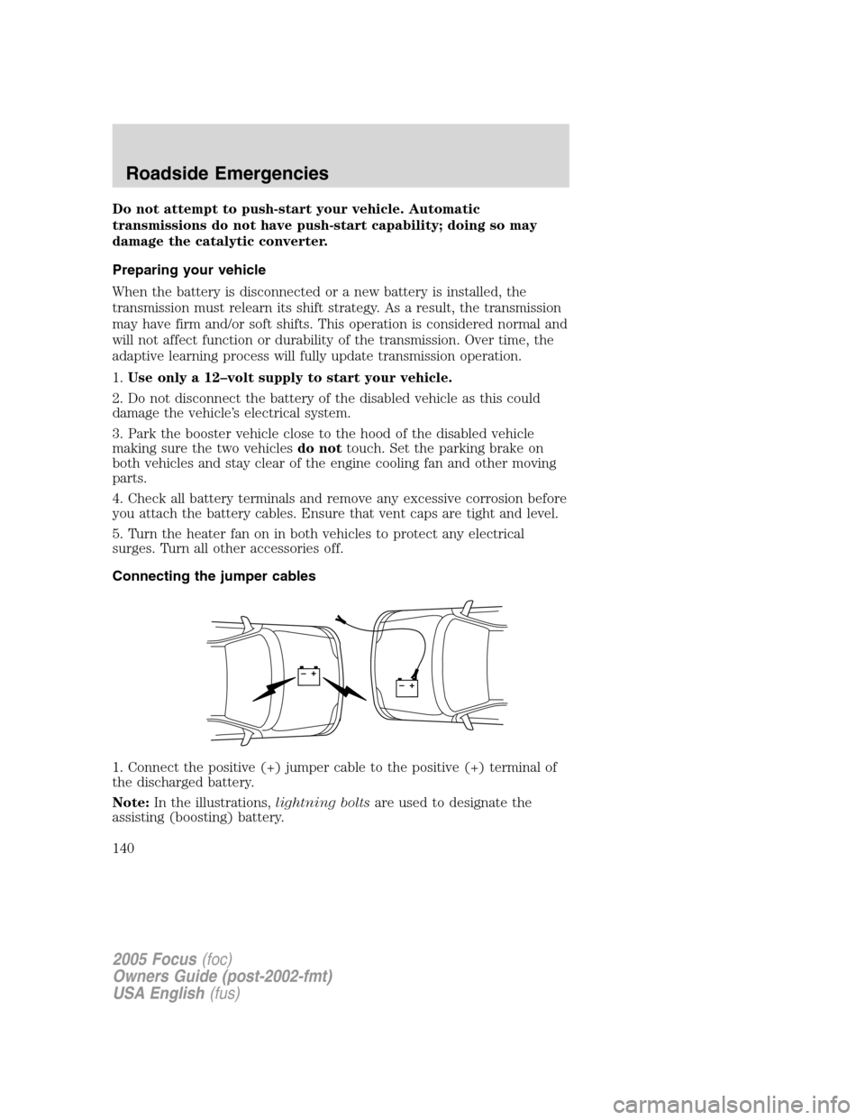
Connecting the jumper cables
1. Connect the positive (+) jumper cable to the positive (+) terminal of
the discharged battery.
Note:In the illustrations,lightning boltsare used to designate the
assisting (boosting) battery.
+–+–
2005 Focus(foc)
Owners Guide (post-2002-fmt)
USA English(fus)
Roadside Emergencies
140