FORD FOCUS ELECTRIC 2014 3.G Owners Manual
Manufacturer: FORD, Model Year: 2014, Model line: FOCUS ELECTRIC, Model: FORD FOCUS ELECTRIC 2014 3.GPages: 403, PDF Size: 6.42 MB
Page 261 of 403
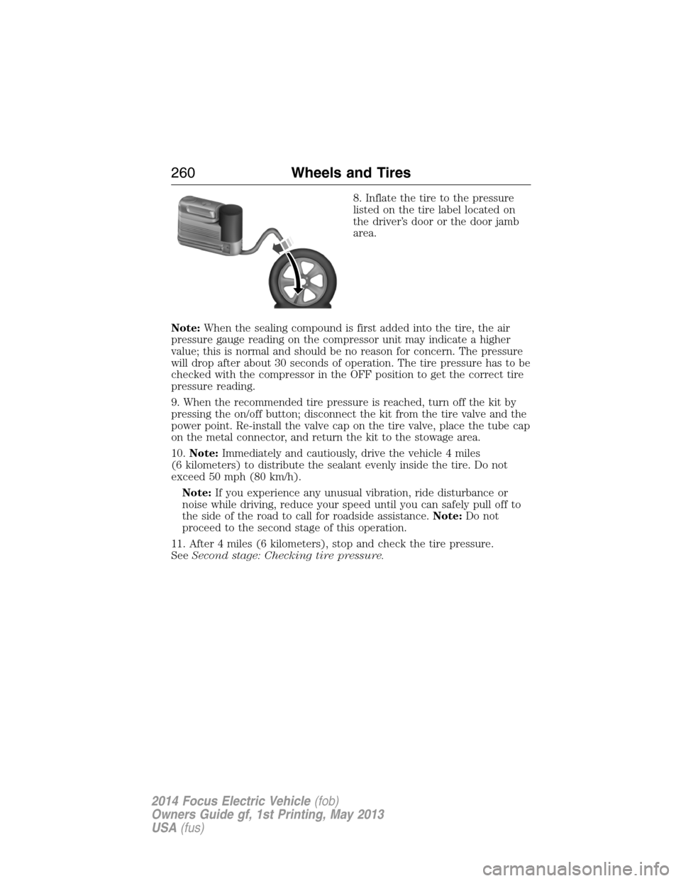
8. Inflate the tire to the pressure
listed on the tire label located on
the driver’s door or the door jamb
area.
Note:When the sealing compound is first added into the tire, the air
pressure gauge reading on the compressor unit may indicate a higher
value; this is normal and should be no reason for concern. The pressure
will drop after about 30 seconds of operation. The tire pressure has to be
checked with the compressor in the OFF position to get the correct tire
pressure reading.
9. When the recommended tire pressure is reached, turn off the kit by
pressing the on/off button; disconnect the kit from the tire valve and the
power point. Re-install the valve cap on the tire valve, place the tube cap
on the metal connector, and return the kit to the stowage area.
10.Note:Immediately and cautiously, drive the vehicle 4 miles
(6 kilometers) to distribute the sealant evenly inside the tire. Do not
exceed 50 mph (80 km/h).
Note:If you experience any unusual vibration, ride disturbance or
noise while driving, reduce your speed until you can safely pull off to
the side of the road to call for roadside assistance.Note:Do not
proceed to the second stage of this operation.
11. After 4 miles (6 kilometers), stop and check the tire pressure.
SeeSecond stage: Checking tire pressure.
260Wheels and Tires
2014 Focus Electric Vehicle(fob)
Owners Guide gf, 1st Printing, May 2013
USA(fus)
Page 262 of 403
Second Stage: Checking Tire Pressure
WARNING:If you are proceeding from theFirst Stage:
Reinflating the Tire with Sealing Compound and Airsection
and have injected sealant in the tire and the pressure is below 20 psi
(1.4 bar), stop and call roadside assistance. If tire pressure is above
20 psi (1.4 bar), continue to the next step.
WARNING:The power plug may get hot after use and should be
handled carefully while unplugging.
Check the air pressure of your tires as follows:
1. Remove the valve cap from the tire valve.
2. Unhook the black hose from the side of the compressor and fasten
firmly on the valve stem by turning clockwise.
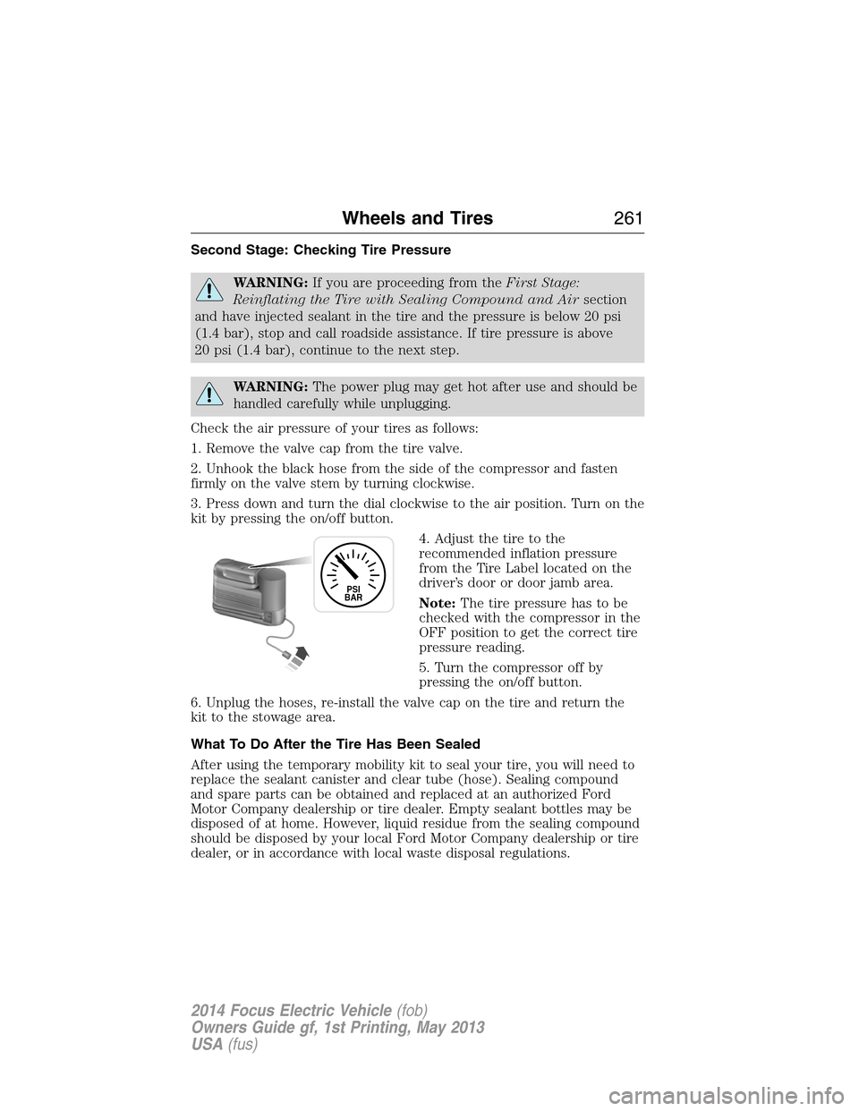
3. Press down and turn the dial clockwise to the air position. Turn on the
kit by pressing the on/off button.
4. Adjust the tire to the
recommended inflation pressure
from the Tire Label located on the
driver’s door or door jamb area.
Note:The tire pressure has to be
checked with the compressor in the
OFF position to get the correct tire
pressure reading.
5. Turn the compressor off by
pressing the on/off button.
6. Unplug the hoses, re-install the valve cap on the tire and return the
kit to the stowage area.
What To Do After the Tire Has Been Sealed
After using the temporary mobility kit to seal your tire, you will need to
replace the sealant canister and clear tube (hose). Sealing compound
and spare parts can be obtained and replaced at an authorized Ford
Motor Company dealership or tire dealer. Empty sealant bottles may be
disposed of at home. However, liquid residue from the sealing compound
should be disposed by your local Ford Motor Company dealership or tire
dealer, or in accordance with local waste disposal regulations.
PSI
BAR
Wheels and Tires261
2014 Focus Electric Vehicle(fob)
Owners Guide gf, 1st Printing, May 2013
USA(fus)
Page 263 of 403
Note:After the sealing compound has been used, the maximum vehicle
speed is 50 mph (80 km/h) and the maximum driving distance is
120 miles (200 kilometers). The sealed tire should be inspected
immediately.
Note:After sealant use, the tire pressure monitoring system sensor and
valve stem on the wheel must be replaced by an authorized Ford dealer.
You can check the tire pressure anytime within the 120 miles
(200 kilometers) by performing the procedure fromSecond Stage:
Checking Tire Pressurelisted previously.
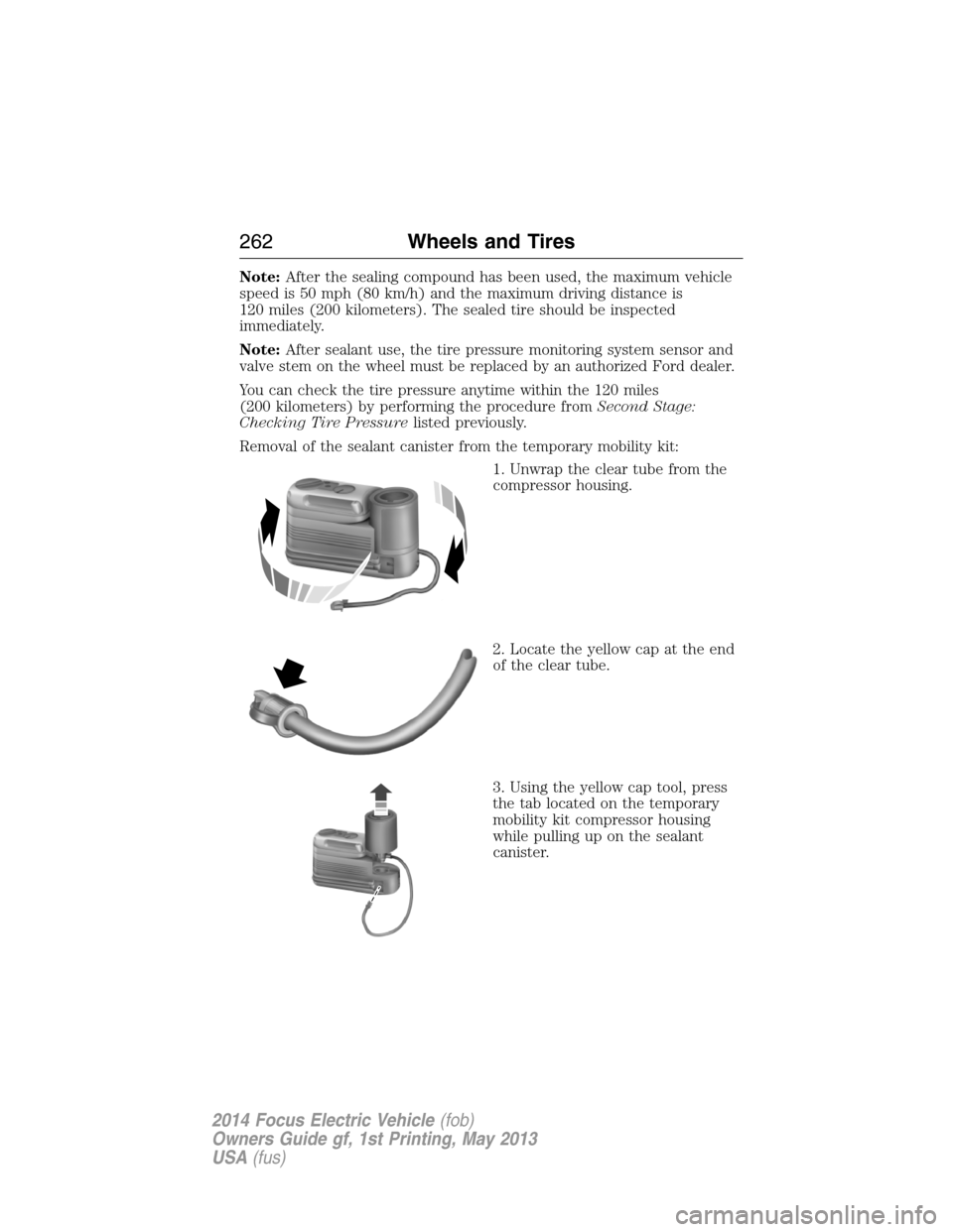
Removal of the sealant canister from the temporary mobility kit:
1. Unwrap the clear tube from the
compressor housing.
2. Locate the yellow cap at the end
of the clear tube.
3. Using the yellow cap tool, press
the tab located on the temporary
mobility kit compressor housing
while pulling up on the sealant
canister.
262Wheels and Tires
2014 Focus Electric Vehicle(fob)
Owners Guide gf, 1st Printing, May 2013
USA(fus)
Page 264 of 403
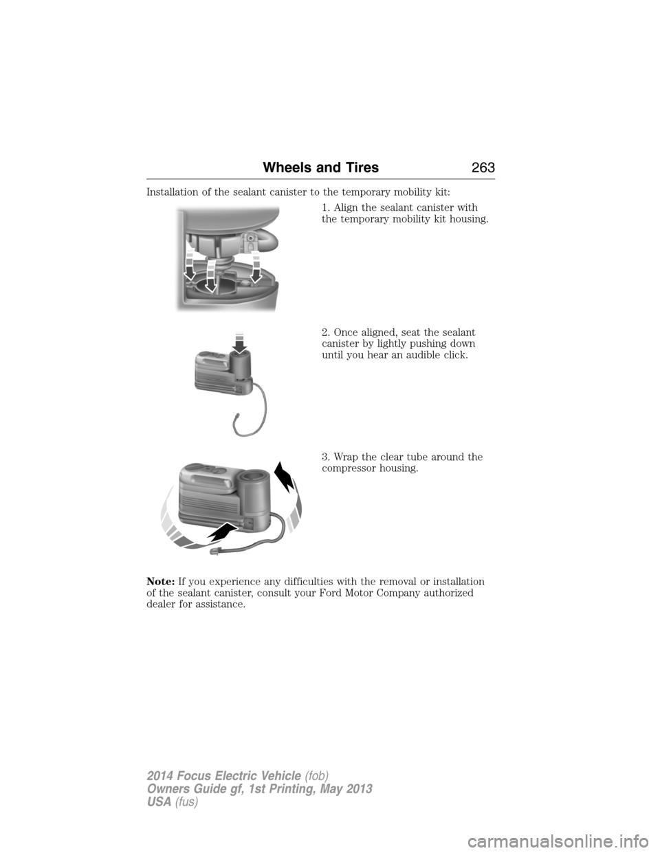
Installation of the sealant canister to the temporary mobility kit:
1. Align the sealant canister with
the temporary mobility kit housing.
2. Once aligned, seat the sealant
canister by lightly pushing down
until you hear an audible click.
3. Wrap the clear tube around the
compressor housing.
Note:If you experience any difficulties with the removal or installation
of the sealant canister, consult your Ford Motor Company authorized
dealer for assistance.
Wheels and Tires263
2014 Focus Electric Vehicle(fob)
Owners Guide gf, 1st Printing, May 2013
USA(fus)
Page 265 of 403
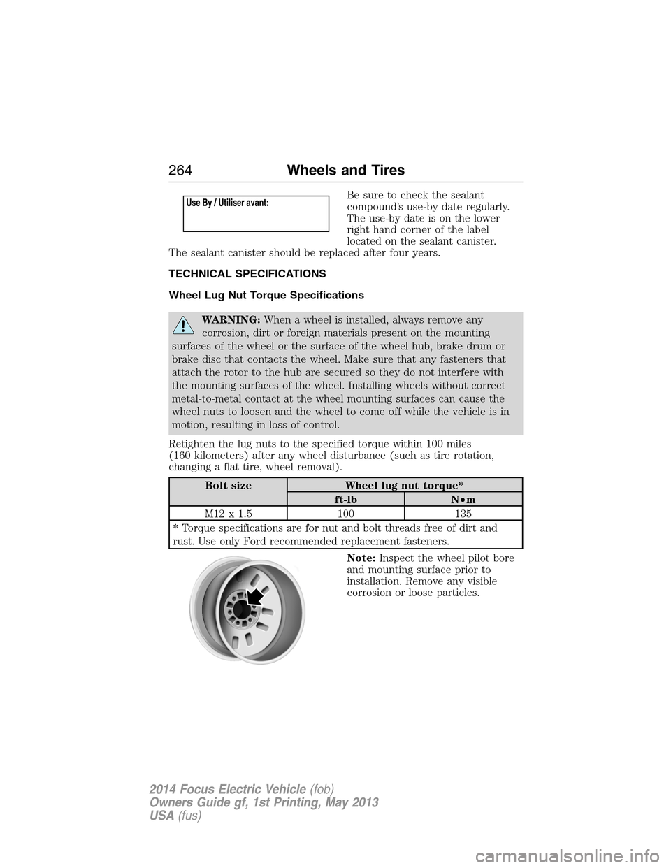
Be sure to check the sealant
compound’s use-by date regularly.
The use-by date is on the lower
right hand corner of the label
located on the sealant canister.
The sealant canister should be replaced after four years.
TECHNICAL SPECIFICATIONS
Wheel Lug Nut Torque Specifications
WARNING:When a wheel is installed, always remove any
corrosion, dirt or foreign materials present on the mounting
surfaces of the wheel or the surface of the wheel hub, brake drum or
brake disc that contacts the wheel. Make sure that any fasteners that
attach the rotor to the hub are secured so they do not interfere with
the mounting surfaces of the wheel. Installing wheels without correct
metal-to-metal contact at the wheel mounting surfaces can cause the
wheel nuts to loosen and the wheel to come off while the vehicle is in
motion, resulting in loss of control.
Retighten the lug nuts to the specified torque within 100 miles
(160 kilometers) after any wheel disturbance (such as tire rotation,
changing a flat tire, wheel removal).
Bolt size Wheel lug nut torque*
ft-lb N•m
M12 x 1.5 100 135
* Torque specifications are for nut and bolt threads free of dirt and
rust. Use only Ford recommended replacement fasteners.
Note:Inspect the wheel pilot bore
and mounting surface prior to
installation. Remove any visible
corrosion or loose particles.
264Wheels and Tires
2014 Focus Electric Vehicle(fob)
Owners Guide gf, 1st Printing, May 2013
USA(fus)
Page 266 of 403
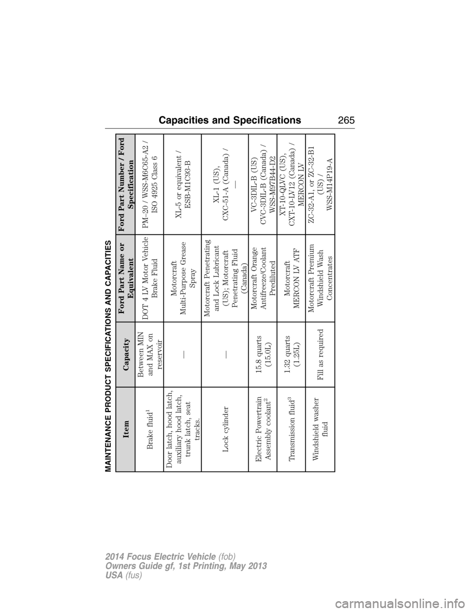
MAINTENANCE PRODUCT SPECIFICATIONS AND CAPACITIES
Item CapacityFord Part Name or
EquivalentFord Part Number / Ford
Specification
Brake fluid
1
Between MIN
and MAX on
reservoirDOT 4 LV Motor Vehicle
Brake FluidPM–20 / WSS-M6C65-A2 /
ISO 4925 Class 6
Door latch, hood latch,
auxiliary hood latch,
trunk latch, seat
tracks.—Motorcraft
Multi-Purpose Grease
SprayXL-5 or equivalent /
ESB-M1C93-B
Lock cylinder —Motorcraft Penetrating
and Lock Lubricant
(US); Motorcraft
Penetrating Fluid
(Canada)XL-1 (US),
CXC-51-A (Canada) /
—
Electric Powertrain
Assembly coolant
2
15.8 quarts
(15.0L)Motorcraft Orange
Antifreeze/Coolant
PredilutedVC-3DIL-B (US)
CVC-3DIL-B (Canada) /
WSS-M97B44-D2
Transmission fluid
3
1.32 quarts
(1.25L)Motorcraft
MERCON LV ATFXT-10-QLVC (US),
CXT-10-LV12 (Canada) /
MERCON LV
Windshield washer
fluidFill as requiredMotorcraft Premium
Windshield Wash
ConcentratesZC-32-A1, or ZC-32-B1
(US) /
WSS-M14P19-A
Capacities and Specifications265
2014 Focus Electric Vehicle(fob)
Owners Guide gf, 1st Printing, May 2013
USA(fus)
Page 267 of 403
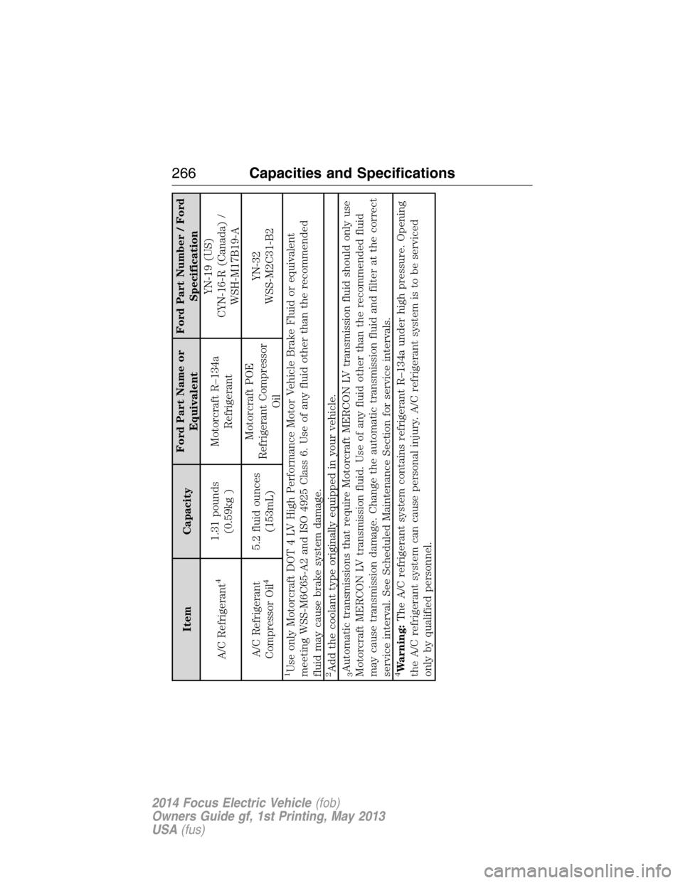
Item CapacityFord Part Name or
EquivalentFord Part Number / Ford
Specification
A/C Refrigerant
4
1.31 pounds
(0.59kg )Motorcraft R–134a
RefrigerantYN-19 (US)
CYN-16-R (Canada) /
WSH-M17B19-A
A/C Refrigerant
Compressor Oil
4
5.2 fluid ounces
(153mL)Motorcraft POE
Refrigerant Compressor
OilYN-32
WSS-M2C31-B2
1Use only Motorcraft DOT 4 LV High Performance Motor Vehicle Brake Fluid or equivalent
meeting WSS-M6C65-A2 and ISO 4925 Class 6. Use of any fluid other than the recommended
fluid may cause brake system damage.2Add the coolant type originally equipped in your vehicle.3Automatic transmissions that require Motorcraft MERCON LV transmission fluid should only use
Motorcraft MERCON LV transmission fluid. Use of any fluid other than the recommended fluid
may cause transmission damage. Change the automatic transmission fluid and filter at the correct
service interval. See Scheduled Maintenance Section for service intervals.4Warning:The A/C refrigerant system contains refrigerant R–134a under high pressure. Opening
the A/C refrigerant system can cause personal injury. A/C refrigerant system is to be serviced
only by qualified personnel.
266Capacities and Specifications
2014 Focus Electric Vehicle(fob)
Owners Guide gf, 1st Printing, May 2013
USA(fus)
Page 268 of 403
MOTORCRAFT PART NUMBERS
Component Part number
12 Volt battery BXT-96R-500/BXT-96R-590
Cabin air filter FP70
Windshield wiper blade Driver’s side: WW2802
Passenger side: WW2803
Rear wiper blade WW1204
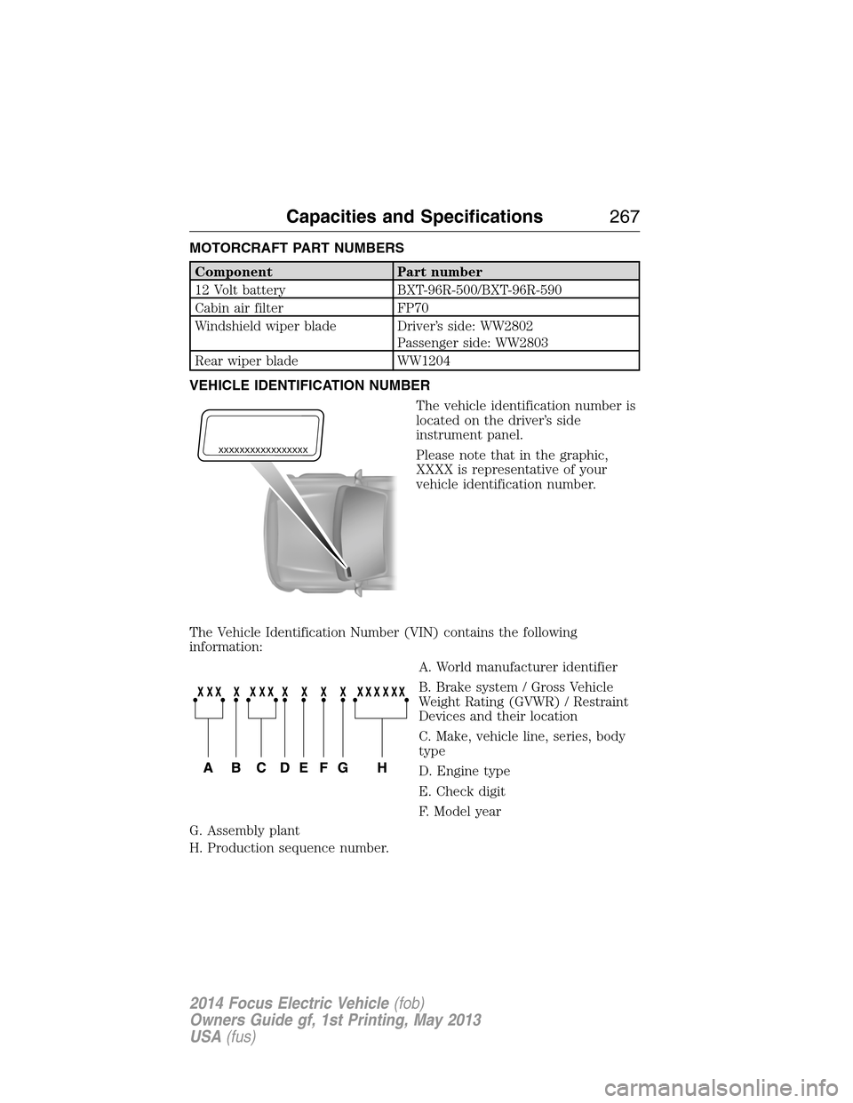
VEHICLE IDENTIFICATION NUMBER
The vehicle identification number is
located on the driver’s side
instrument panel.
Please note that in the graphic,
XXXX is representative of your
vehicle identification number.
The Vehicle Identification Number (VIN) contains the following
information:
A. World manufacturer identifier
B. Brake system / Gross Vehicle
Weight Rating (GVWR) / Restraint
Devices and their location
C. Make, vehicle line, series, body
type
D. Engine type
E. Check digit
F. Model year
G. Assembly plant
H. Production sequence number.
XXXXXXXXXXXXXXXXX
Capacities and Specifications267
2014 Focus Electric Vehicle(fob)
Owners Guide gf, 1st Printing, May 2013
USA(fus)
Page 269 of 403
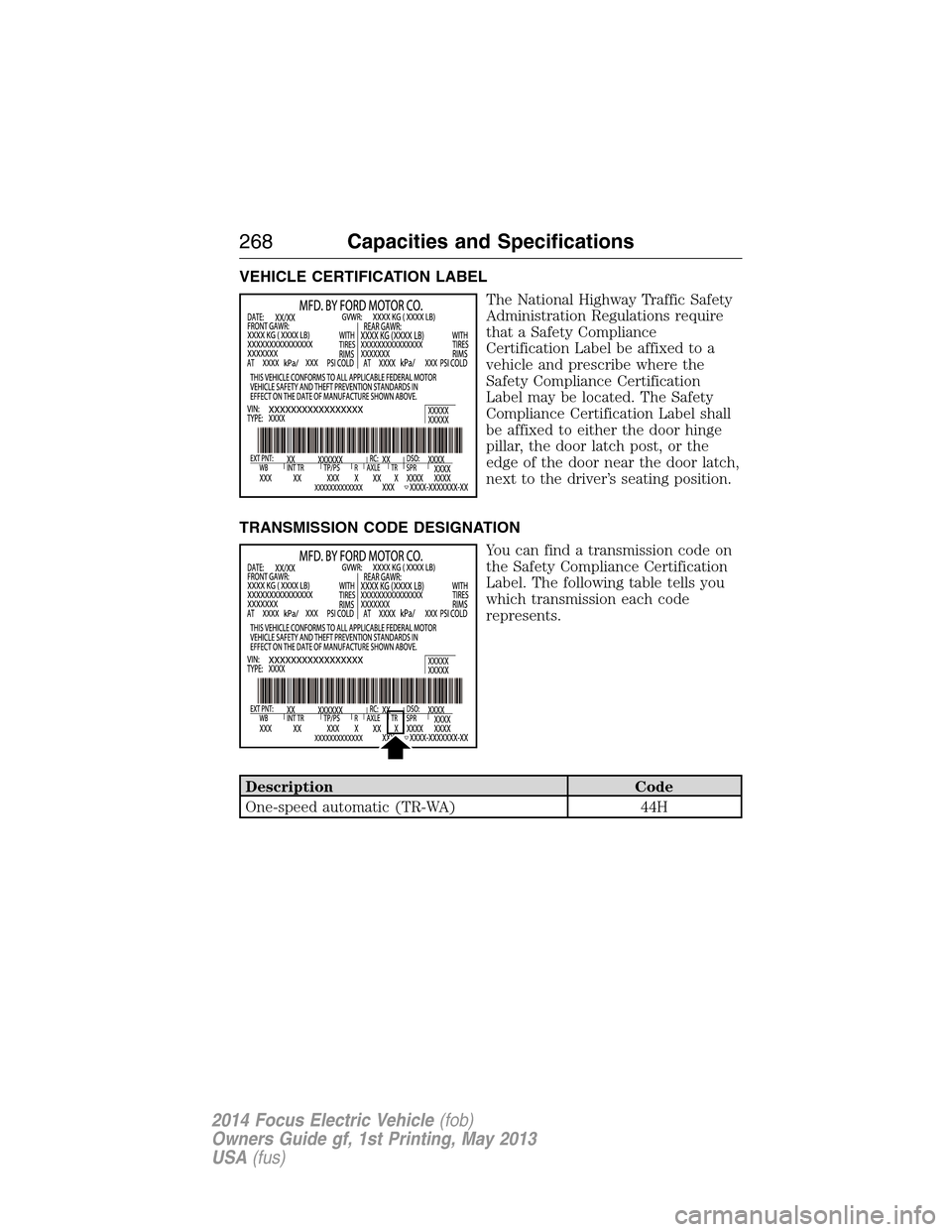
VEHICLE CERTIFICATION LABEL
The National Highway Traffic Safety
Administration Regulations require
that a Safety Compliance
Certification Label be affixed to a
vehicle and prescribe where the
Safety Compliance Certification
Label may be located. The Safety
Compliance Certification Label shall
be affixed to either the door hinge
pillar, the door latch post, or the
edge of the door near the door latch,
next to the driver’s seating position.
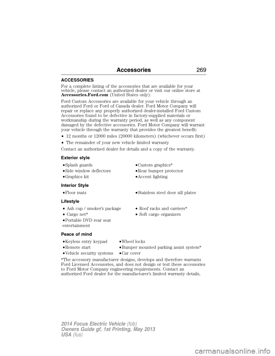
TRANSMISSION CODE DESIGNATION
You can find a transmission code on
the Safety Compliance Certification
Label. The following table tells you
which transmission each code
represents.
Description Code
One-speed automatic (TR-WA) 44H
268Capacities and Specifications
2014 Focus Electric Vehicle(fob)
Owners Guide gf, 1st Printing, May 2013
USA(fus)
Page 270 of 403
ACCESSORIES
For a complete listing of the accessories that are available for your
vehicle, please contact an authorized dealer or visit our online store at
Accessories.Ford.com(United States only).
Ford Custom Accessories are available for your vehicle through an
authorized Ford or Ford of Canada dealer. Ford Motor Company will
repair or replace any properly authorized dealer-installed Ford Custom
Accessories found to be defective in factory-supplied materials or
workmanship during the warranty period, as well as any component
damaged by the defective accessories. Ford Motor Company will warrant
your vehicle through the warranty that provides the greatest benefit:
•12 months or 12000 miles (20000 kilometers) (whichever occurs first)
•The remainder of your new vehicle limited warranty
Contact an authorized dealer for details and a copy of the warranty.
Exterior style
•Splash guards•Custom graphics*
•Side window deflectors•Rear bumper protector
•Graphics kit•Accent lighting
Interior Style
•Floor mats•Stainless steel door sill plates
Lifestyle
•Ash cup / smoker’s package•Roof racks and carriers*
•Cargo net*•Soft cargo organizers
•Portable DVD rear seat
entertainment
Peace of mind
•Keyless entry keypad•Wheel locks
•Remote start•Bumper mounted parking assist system*
•Vehicle security systems•Car cover
*The accessory manufacturer designs, develops and therefore warrants
Ford Licensed Accessories, and does not design or test these accessories
to Ford Motor Company engineering requirements. Contact an
authorized Ford dealer for the manufacturer’s limited warranty details,
Accessories269
2014 Focus Electric Vehicle(fob)
Owners Guide gf, 1st Printing, May 2013
USA(fus)