clock FORD FUSION 2020 User Guide
[x] Cancel search | Manufacturer: FORD, Model Year: 2020, Model line: FUSION, Model: FORD FUSION 2020Pages: 497, PDF Size: 6.64 MB
Page 276 of 497
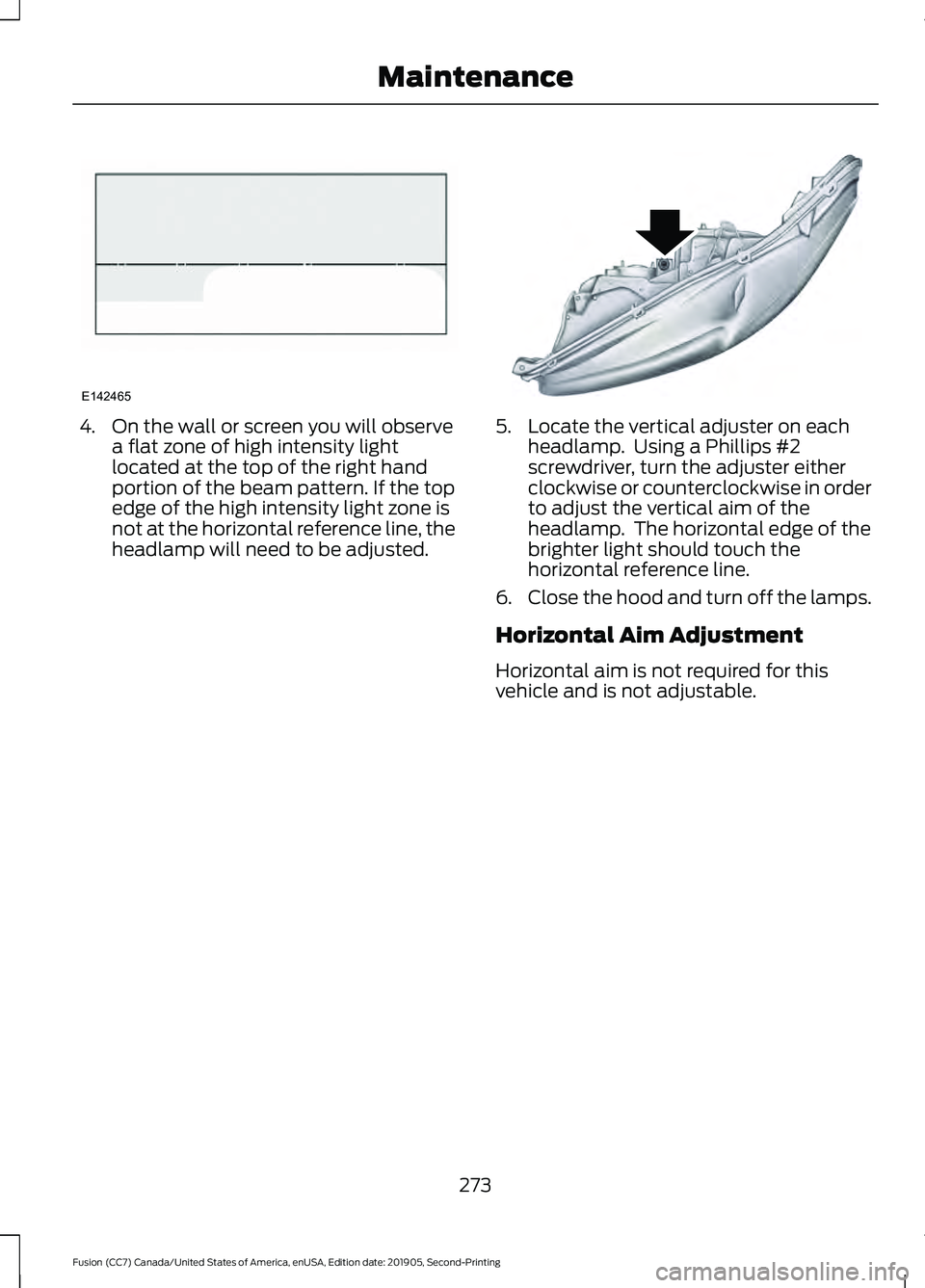
4. On the wall or screen you will observe
a flat zone of high intensity light
located at the top of the right hand
portion of the beam pattern. If the top
edge of the high intensity light zone is
not at the horizontal reference line, the
headlamp will need to be adjusted. 5. Locate the vertical adjuster on each
headlamp. Using a Phillips #2
screwdriver, turn the adjuster either
clockwise or counterclockwise in order
to adjust the vertical aim of the
headlamp. The horizontal edge of the
brighter light should touch the
horizontal reference line.
6. Close the hood and turn off the lamps.
Horizontal Aim Adjustment
Horizontal aim is not required for this
vehicle and is not adjustable.
273
Fusion (CC7) Canada/United States of America, enUSA, Edition date: 201905, Second-Printing MaintenanceE142465 E145594
Page 277 of 497
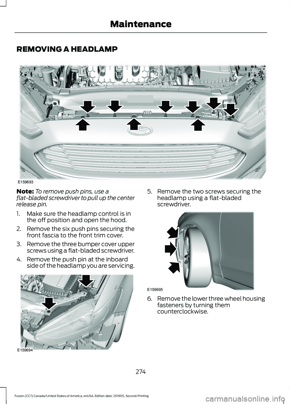
REMOVING A HEADLAMP
Note:
To remove push pins, use a
flat-bladed screwdriver to pull up the center
release pin.
1. Make sure the headlamp control is in the off position and open the hood.
2. Remove the six push pins securing the
front fascia to the front trim cover.
3. Remove the three bumper cover upper
screws using a flat-bladed screwdriver.
4. Remove the push pin at the inboard side of the headlamp you are servicing. 5. Remove the two screws securing the
headlamp using a flat-bladed
screwdriver. 6.
Remove the lower three wheel housing
fasteners by turning them
counterclockwise.
274
Fusion (CC7) Canada/United States of America, enUSA, Edition date: 201905, Second-Printing MaintenanceE159693 E159694 E159695
Page 278 of 497
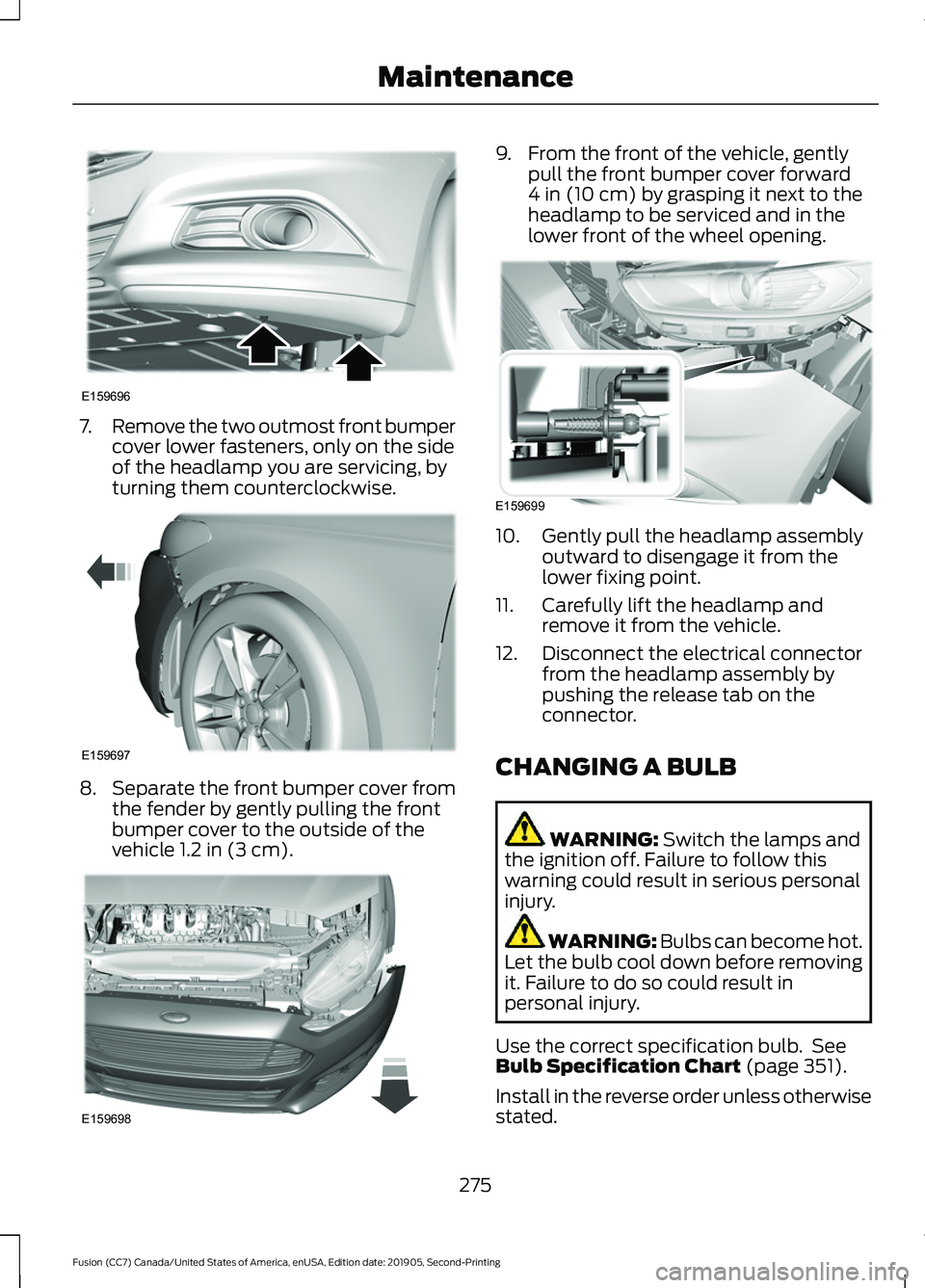
7.
Remove the two outmost front bumper
cover lower fasteners, only on the side
of the headlamp you are servicing, by
turning them counterclockwise. 8.
Separate the front bumper cover from
the fender by gently pulling the front
bumper cover to the outside of the
vehicle 1.2 in (3 cm). 9. From the front of the vehicle, gently
pull the front bumper cover forward
4 in (10 cm)
by grasping it next to the
headlamp to be serviced and in the
lower front of the wheel opening. 10. Gently pull the headlamp assembly
outward to disengage it from the
lower fixing point.
11. Carefully lift the headlamp and remove it from the vehicle.
12. Disconnect the electrical connector from the headlamp assembly by
pushing the release tab on the
connector.
CHANGING A BULB WARNING:
Switch the lamps and
the ignition off. Failure to follow this
warning could result in serious personal
injury. WARNING: Bulbs can become hot.
Let the bulb cool down before removing
it. Failure to do so could result in
personal injury.
Use the correct specification bulb. See
Bulb Specification Chart
(page 351).
Install in the reverse order unless otherwise
stated.
275
Fusion (CC7) Canada/United States of America, enUSA, Edition date: 201905, Second-Printing MaintenanceE159696 E159697 E159698 E159699
Page 279 of 497
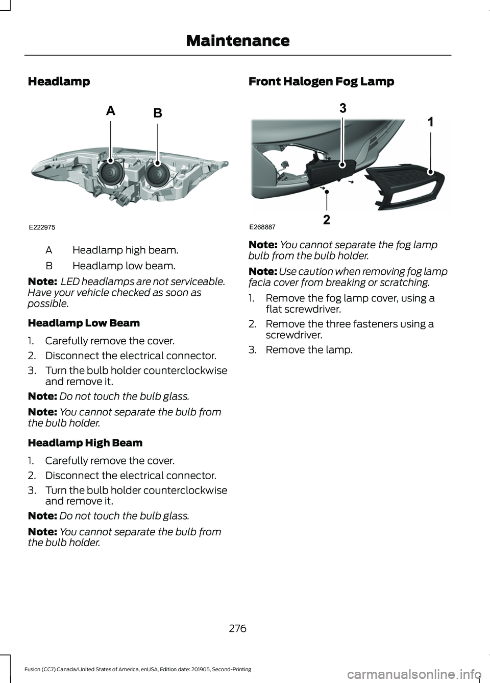
Headlamp
Headlamp high beam.
A
Headlamp low beam.
B
Note: LED headlamps are not serviceable.
Have your vehicle checked as soon as
possible.
Headlamp Low Beam
1. Carefully remove the cover.
2. Disconnect the electrical connector.
3. Turn the bulb holder counterclockwise
and remove it.
Note: Do not touch the bulb glass.
Note: You cannot separate the bulb from
the bulb holder.
Headlamp High Beam
1. Carefully remove the cover.
2. Disconnect the electrical connector.
3. Turn the bulb holder counterclockwise
and remove it.
Note: Do not touch the bulb glass.
Note: You cannot separate the bulb from
the bulb holder. Front Halogen Fog Lamp
Note:
You cannot separate the fog lamp
bulb from the bulb holder.
Note: Use caution when removing fog lamp
facia cover from breaking or scratching.
1. Remove the fog lamp cover, using a flat screwdriver.
2. Remove the three fasteners using a screwdriver.
3. Remove the lamp.
276
Fusion (CC7) Canada/United States of America, enUSA, Edition date: 201905, Second-Printing MaintenanceE222975
AB E268887
Page 280 of 497
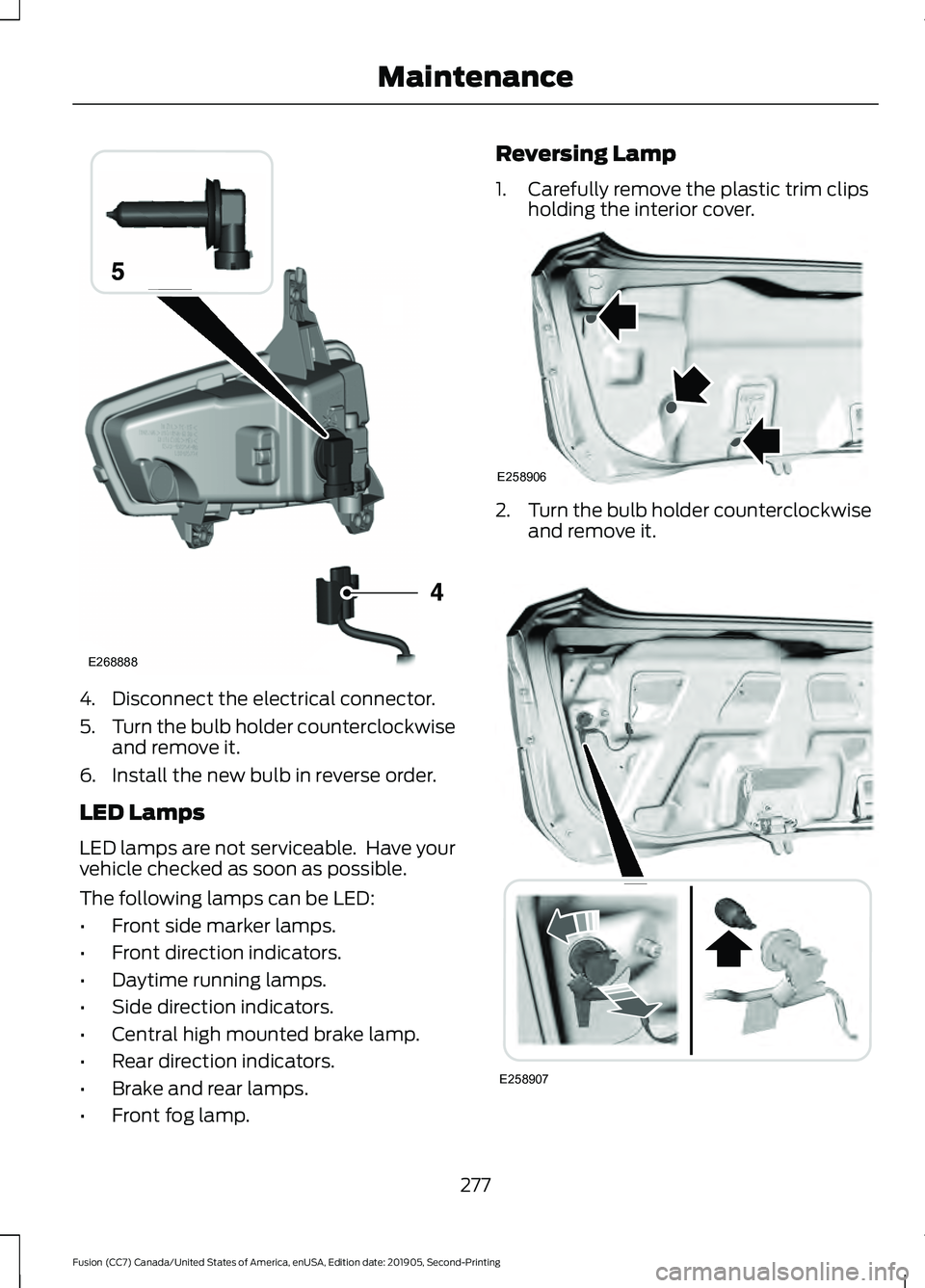
4. Disconnect the electrical connector.
5.
Turn the bulb holder counterclockwise
and remove it.
6. Install the new bulb in reverse order.
LED Lamps
LED lamps are not serviceable. Have your
vehicle checked as soon as possible.
The following lamps can be LED:
• Front side marker lamps.
• Front direction indicators.
• Daytime running lamps.
• Side direction indicators.
• Central high mounted brake lamp.
• Rear direction indicators.
• Brake and rear lamps.
• Front fog lamp. Reversing Lamp
1. Carefully remove the plastic trim clips
holding the interior cover. 2.
Turn the bulb holder counterclockwise
and remove it. 277
Fusion (CC7) Canada/United States of America, enUSA, Edition date: 201905, Second-Printing MaintenanceE268888 E258906 E258907
Page 281 of 497
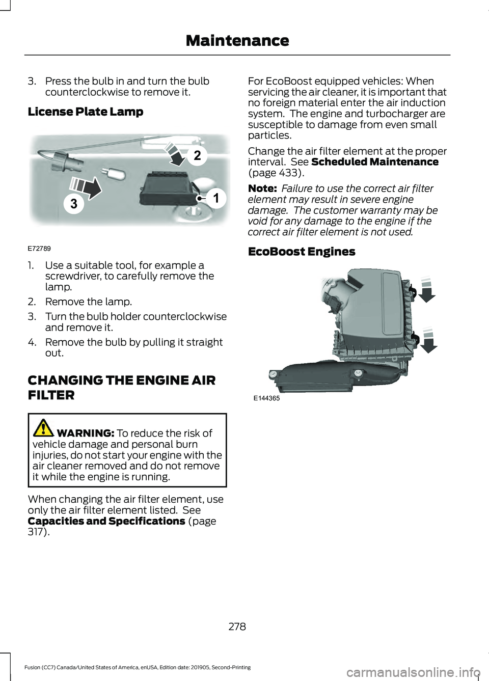
3. Press the bulb in and turn the bulb
counterclockwise to remove it.
License Plate Lamp 1. Use a suitable tool, for example a
screwdriver, to carefully remove the
lamp.
2. Remove the lamp.
3. Turn the bulb holder counterclockwise
and remove it.
4. Remove the bulb by pulling it straight out.
CHANGING THE ENGINE AIR
FILTER WARNING: To reduce the risk of
vehicle damage and personal burn
injuries, do not start your engine with the
air cleaner removed and do not remove
it while the engine is running.
When changing the air filter element, use
only the air filter element listed. See
Capacities and Specifications
(page
317). For EcoBoost equipped vehicles: When
servicing the air cleaner, it is important that
no foreign material enter the air induction
system. The engine and turbocharger are
susceptible to damage from even small
particles.
Change the air filter element at the proper
interval. See
Scheduled Maintenance
(page 433).
Note: Failure to use the correct air filter
element may result in severe engine
damage. The customer warranty may be
void for any damage to the engine if the
correct air filter element is not used.
EcoBoost Engines 278
Fusion (CC7) Canada/United States of America, enUSA, Edition date: 201905, Second-Printing Maintenance3
2
1
E72789 E144365
Page 314 of 497
Note:
Do not allow passengers to remain
in your vehicle when using the jack on the
vehicle.
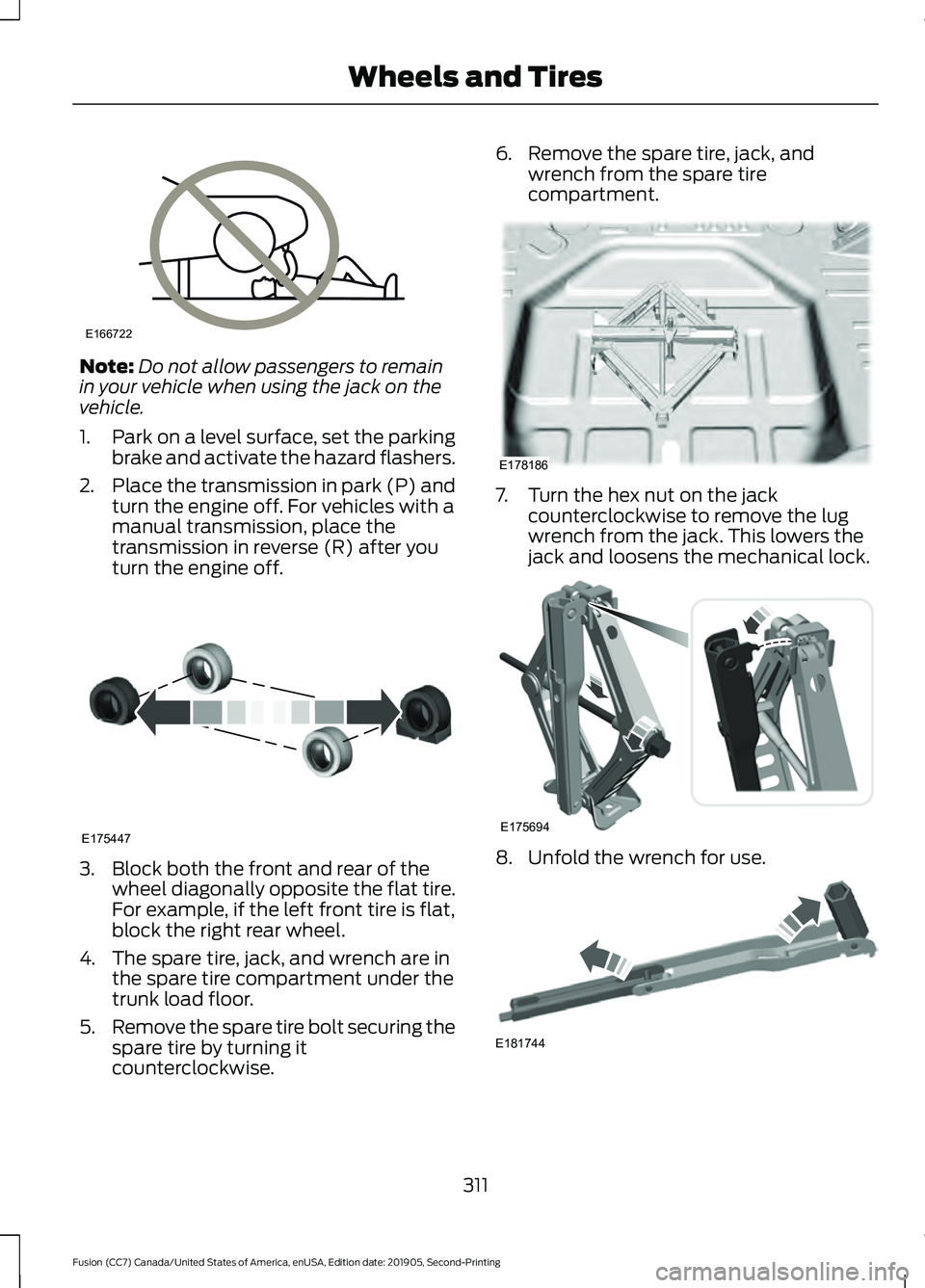
1. Park on a level surface, set the parking
brake and activate the hazard flashers.
2. Place the transmission in park (P) and
turn the engine off. For vehicles with a
manual transmission, place the
transmission in reverse (R) after you
turn the engine off. 3. Block both the front and rear of the
wheel diagonally opposite the flat tire.
For example, if the left front tire is flat,
block the right rear wheel.
4. The spare tire, jack, and wrench are in the spare tire compartment under the
trunk load floor.
5. Remove the spare tire bolt securing the
spare tire by turning it
counterclockwise. 6. Remove the spare tire, jack, and
wrench from the spare tire
compartment. 7. Turn the hex nut on the jack
counterclockwise to remove the lug
wrench from the jack. This lowers the
jack and loosens the mechanical lock. 8. Unfold the wrench for use.
311
Fusion (CC7) Canada/United States of America, enUSA, Edition date: 201905, Second-Printing Wheels and TiresE166722 E175447 E178186 E175694 E181744
Page 315 of 497
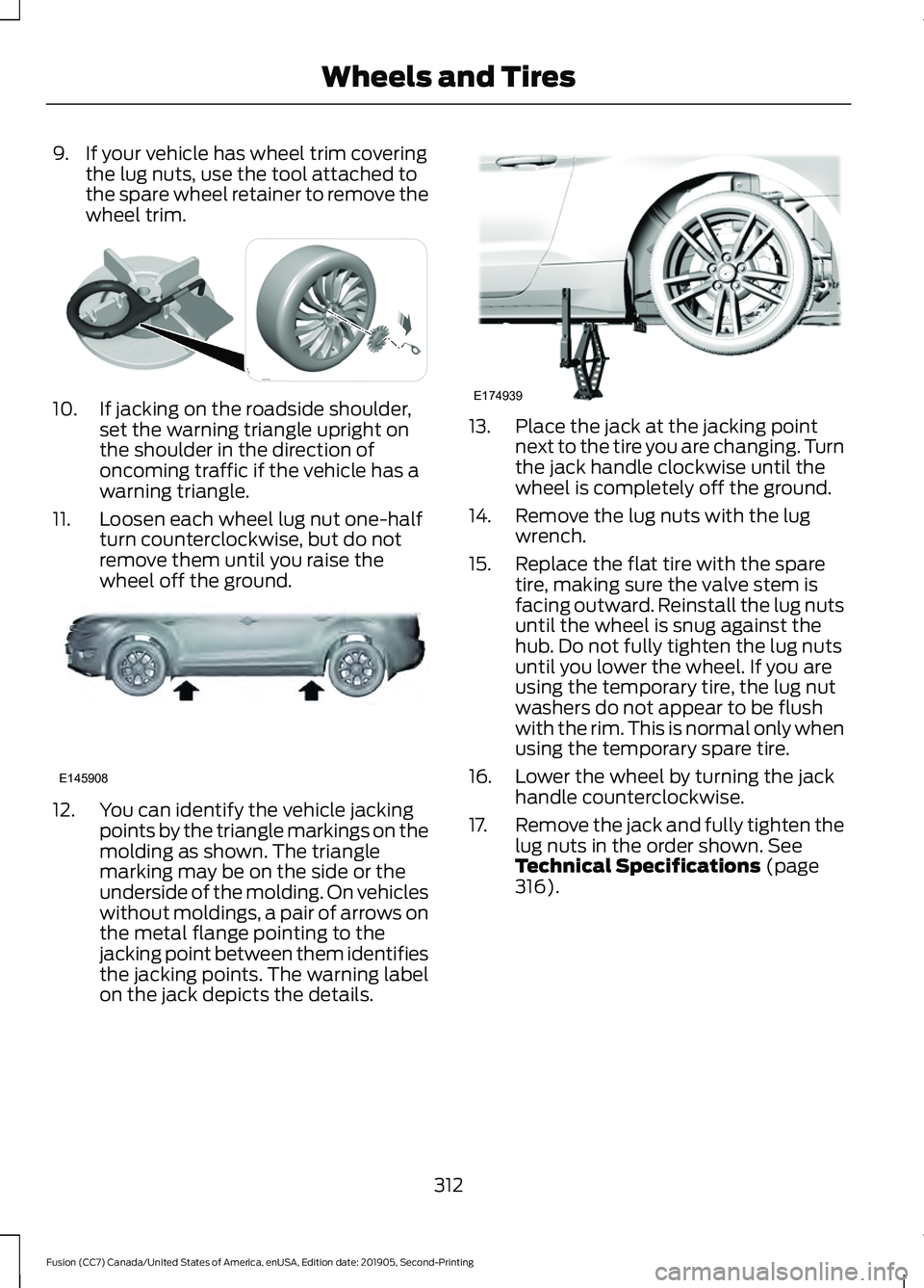
9. If your vehicle has wheel trim covering
the lug nuts, use the tool attached to
the spare wheel retainer to remove the
wheel trim. 10. If jacking on the roadside shoulder,
set the warning triangle upright on
the shoulder in the direction of
oncoming traffic if the vehicle has a
warning triangle.
11. Loosen each wheel lug nut one-half turn counterclockwise, but do not
remove them until you raise the
wheel off the ground.12. You can identify the vehicle jacking
points by the triangle markings on the
molding as shown. The triangle
marking may be on the side or the
underside of the molding. On vehicles
without moldings, a pair of arrows on
the metal flange pointing to the
jacking point between them identifies
the jacking points. The warning label
on the jack depicts the details. 13. Place the jack at the jacking point
next to the tire you are changing. Turn
the jack handle clockwise until the
wheel is completely off the ground.
14. Remove the lug nuts with the lug wrench.
15. Replace the flat tire with the spare tire, making sure the valve stem is
facing outward. Reinstall the lug nuts
until the wheel is snug against the
hub. Do not fully tighten the lug nuts
until you lower the wheel. If you are
using the temporary tire, the lug nut
washers do not appear to be flush
with the rim. This is normal only when
using the temporary spare tire.
16. Lower the wheel by turning the jack handle counterclockwise.
17. Remove the jack and fully tighten the
lug nuts in the order shown. See
Technical Specifications (page
316).
312
Fusion (CC7) Canada/United States of America, enUSA, Edition date: 201905, Second-Printing Wheels and TiresE302004 E145908 E174939
Page 316 of 497
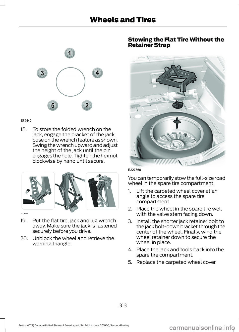
18. To store the folded wrench on the
jack, engage the bracket of the jack
base on the wrench feature as shown.
Swing the wrench upward and adjust
the height of the jack until the pin
engages the hole. Tighten the hex nut
clockwise by hand until secure. 19. Put the flat tire, jack and lug wrench
away. Make sure the jack is fastened
securely before you drive.
20. Unblock the wheel and retrieve the warning triangle. Stowing the Flat Tire Without the
Retainer Strap
You can temporarily stow the full-size road
wheel in the spare tire compartment.
1. Lift the carpeted wheel cover at an
angle to access the spare tire
compartment.
2. Place the wheel in the spare tire well with the valve stem facing down.
3. Install the shorter jack retainer bolt to the jack bolt-down bracket through the
center of the wheel. Finally, wind the
wheel retainer down to secure the
wheel in place.
4. Place the jack and tools back into the spare tire compartment.
5. Replace the carpeted wheel cover.
313
Fusion (CC7) Canada/United States of America, enUSA, Edition date: 201905, Second-Printing Wheels and Tires12
3
4
5
E75442 E176165 E227869
Page 362 of 497
hand-held device while driving and
encourage the use of voice-operated
systems when possible. Make sure you
are aware of all applicable local laws
that may affect the use of electronic
devices while driving.
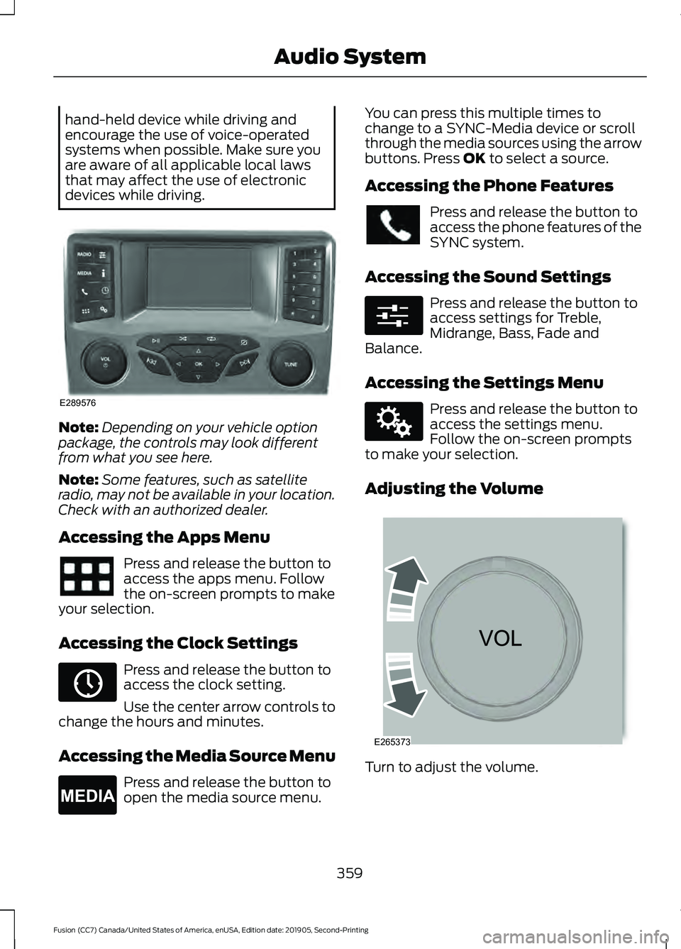
Note:
Depending on your vehicle option
package, the controls may look different
from what you see here.
Note: Some features, such as satellite
radio, may not be available in your location.
Check with an authorized dealer.
Accessing the Apps Menu Press and release the button to
access the apps menu. Follow
the on-screen prompts to make
your selection.
Accessing the Clock Settings Press and release the button to
access the clock setting.
Use the center arrow controls to
change the hours and minutes.
Accessing the Media Source Menu Press and release the button to
open the media source menu. You can press this multiple times to
change to a SYNC-Media device or scroll
through the media sources using the arrow
buttons. Press OK to select a source.
Accessing the Phone Features Press and release the button to
access the phone features of the
SYNC system.
Accessing the Sound Settings Press and release the button to
access settings for Treble,
Midrange, Bass, Fade and
Balance.
Accessing the Settings Menu Press and release the button to
access the settings menu.
Follow the on-screen prompts
to make your selection.
Adjusting the Volume Turn to adjust the volume.
359
Fusion (CC7) Canada/United States of America, enUSA, Edition date: 201905, Second-Printing Audio SystemE289576 E265036 E265035 E280315 E142607 E265373