auxiliary battery location FORD GRANADA 1985 Service Repair Manual
[x] Cancel search | Manufacturer: FORD, Model Year: 1985, Model line: GRANADA, Model: FORD GRANADA 1985Pages: 255, PDF Size: 14.98 MB
Page 7 of 255
1•6Maintenance Procedures
This Chapter is designed to help the home
mechanic maintain his/her vehicle for safety,
economy, long life and peak performance.
The Chapter contains a master maintenance
schedule, followed by Sections dealing
specifically with each task in the schedule.
Visual checks, adjustments, component
renewal and other helpful items are included.
Refer to the accompanying illustrations of the
engine compartment and the underside of the
vehicle for the locations of the various
components.
Servicing your vehicle in accordance with
the mileage/time maintenance schedule and
the following Sections will provide a planned
maintenance programme, which should result
in a long and reliable service life. This is a
comprehensive plan, so maintaining some
items but not others at the specified service
intervals, will not produce the same results.
As you service your vehicle, you will
discover that many of the procedures can -
and should - be grouped together, because of
the particular procedure being performed, or
because of the close proximity of two
otherwise-unrelated components to one
another. For example, if the vehicle is raised
for any reason, the exhaust can be inspected
at the same time as the suspension and
steering components.
The first step in this maintenanceprogramme is to prepare yourself before the
actual work begins. Read through all the
Sections relevant to the work to be carried out,
then make a list and gather together all the
parts and tools required. If a problem is
encountered, seek advice from a parts
specialist, or a dealer service department.
If, from the time the vehicle is new, the
routine maintenance schedule is followed
closely, and frequent checks are made of fluid
levels and high-wear items, as suggested
throughout this manual, the engine will be kept
in relatively good running condition, and the
need for additional work will be minimised.
It is possible that there will be times when
the engine is running poorly due to the lack of
regular maintenance. This is even more likely if
a used vehicle, which has not received regular
and frequent maintenance checks, is
purchased. In such cases, additional work
may need to be carried out, outside of the
regular maintenance intervals.
If engine wear is suspected, a compression
test will provide valuable information regarding
the overall performance of the main internal
components. Such a test can be used as a
basis to decide on the extent of the work to be
carried out. If, for example, a compression test
indicates serious internal engine wear,
conventional maintenance as described in this
Chapter will not greatly improve theperformance of the engine, and may prove a
waste of time and money, unless extensive
overhaul work is carried out first.
The following series of operations are those
most often required to improve the
performance of a generally poor-running
engine:
Primary operations
a)Clean, inspect and test the battery
(Section 6)
b)Check all the engine-related fluids
(Section 3).
c)Check the condition and tension of the
auxiliary drivebelt (Section 21).
d)Renew the spark plugs (Section 20).
e)Inspect the distributor cap, rotor arm and
HT leads - as applicable (Chapter 5).
f)Check the condition of the air cleaner filter
element, and renew if necessary (Section 38).
g)Renew the fuel filter (Section 41).
h)Check the condition of all hoses, and
check for fluid leaks (Section 10).
i)Check the idle speed and mixture settings
- as applicable (Chapter 4).
If the above operations do not prove fully
effective, carry out the following secondary
operations:
Secondary operations
a)Check the charging system (Chapter 5).
b)Check the ignition system (Chapter 5).
c)Check the fuel system (Chapter 4).
d)Renew the distributor cap and rotor arm -
as applicable (Chapter 5).
f)Renew the ignition HT leads - as
applicable (Chapter 5).
2Intensive maintenance
1Introduction
Engine oil
1Check the oil level as follows.
2With the vehicle parked on level ground,
and with the engine having been stopped for a
few minutes, open and prop the bonnet.
Withdraw the dipstick, wipe it on a clean ragand re-insert it fully. Withdraw it again and
read the oil level relative to the marks on the
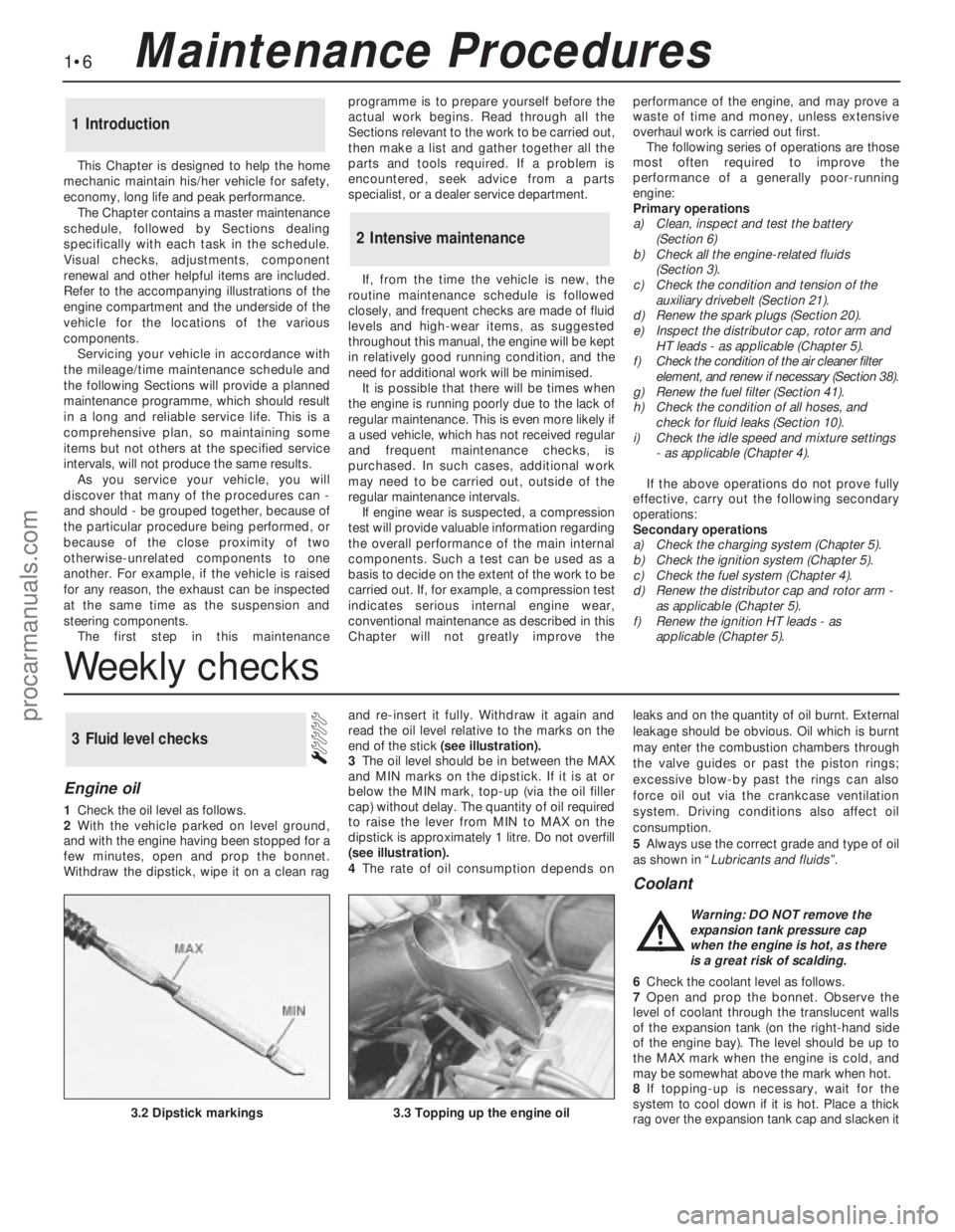
end of the stick (see illustration).
3The oil level should be in between the MAX
and MIN marks on the dipstick. If it is at or
below the MIN mark, top-up (via the oil filler
cap) without delay. The quantity of oil required
to raise the lever from MIN to MAX on the
dipstick is approximately 1 litre. Do not overfill
(see illustration).
4The rate of oil consumption depends onleaks and on the quantity of oil burnt. External
leakage should be obvious. Oil which is burnt
may enter the combustion chambers through
the valve guides or past the piston rings;
excessive blow-by past the rings can also
force oil out via the crankcase ventilation
system. Driving conditions also affect oil
consumption.
5Always use the correct grade and type of oil
as shown in “Lubricants and fluids”.
Coolant
6Check the coolant level as follows.
7Open and prop the bonnet. Observe the
level of coolant through the translucent walls
of the expansion tank (on the right-hand side
of the engine bay). The level should be up to
the MAX mark when the engine is cold, and
may be somewhat above the mark when hot.
8If topping-up is necessary, wait for the
system to cool down if it is hot. Place a thick
rag over the expansion tank cap and slacken it
3Fluid level checks
3.2 Dipstick markings3.3 Topping up the engine oil
Warning: DO NOT remove the
expansion tank pressure cap
when the engine is hot, as there
is a great risk of scalding.
Weekly checks
procarmanuals.com
Page 28 of 255
The cylinder head is of crossflow design
with the inlet manifold mounted on the left-
hand side and the exhaust manifold mounted
on the right-hand side.
Lubrication is by means of a bi-rotor pump
which draws oil through a strainer located
inside the sump, and forces it through a full-
flow filter into the engine oil galleries where it
is distributed to the crankshaft, camshaft and
auxiliary shaft. The big-end bearings are
supplied with oil via internal drillings in the
crankshaft.The undersides of the pistons are
supplied with oil from drillings in the big-ends.
The distributor shaft is intermittently supplied
with oil from the drilled auxiliary shaft. The
camshaft and cam followers are supplied with
oil via a drilled spray tube from the centre
camshaft bearing.
A semi-closed crankcase ventilation system
is employed whereby piston blow-by gases
are drawn into the inlet manifold via an oil
separator and on carburettor models a control
valve.
The following operations can be carried out
without removing the engine, although the
work may be easier and quicker with the
engine removed:
a)Removal and refitting of the cylinder head
b)Removal and refitting of the camshaft
(after removing the cylinder head)
c)Removal and refitting of the timing belt
and sprockets
d)Removal and refitting of the sump and oil
pump
e)Removal and refitting of the pistons,
connecting rods and big-end bearings
f)Renewal of the engine mountings
g)Renewal of the crankshaft oil seals
h)Removal and refitting of the auxiliary shaft
j)Removal and refitting of the flywheel
The engine must be removed from the
vehicle for the following operations:
a)Renewal of the crankshaft main bearings
b)Removal and refitting of the crankshaft
The engine may be lifted out either on its
own or together with the gearbox. Unless work
is also necessary on the gearbox it is
recommended that the engine is removed on
its own. Where automatic transmission is
fitted, the engine should be removed on its
own owing to the additional weight. If the
engine and gearbox are removed together,
they will have to be tilted at a very steep angle;
make sure that the range of the lifting tackle is
adequate.1Disconnect the battery negative lead.
2Remove the bonnet.
3On carburettor models, remove the air
cleaner. On fuel-injection models, remove the
air cleaner cover, vane airflow meter and air
inlet trunking.
4If a splash guard is fitted, remove it.
5Release the securing clips and bolts and
remove the upper half of the fan shroud. On
carburettor models remove the lower half of
the shroud too.
6Drain the cooling system.
7Disconnect the radiator top and bottom
hoses from the thermostat housing and water
pump. Disconnect the top hose spur from the
expansion tank and unclip it.
8Disconnect the heater hoses from the water
pump and from the inlet manifold or automatic
choke housing. Unclip the hoses.
9On models with power steering, remove the
steering pump.
10Disconnect the vacuum pipe(s) from the
inlet manifold, labelling them if there is any
possibility of confusion.
11Disconnect the following wiring, as
applicable:
a)Alternator
b)Temperature gauge sender
c)Engine management temperature sensor
d)Distributor
e)Oil pressure switch
f)Automatic choke and thermo-switch
g)Carburettor stepper motor
h)Fuel-injection system sub-harness
j)Inlet manifold heater
12Disconnect the HT lead from the coil.
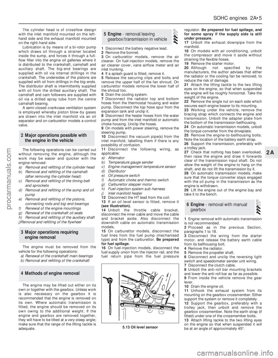
13If an oil level sensor is fitted, remove it
(see illustration).
14Unbolt the throttle cable bracket,
disconnect the inner cable and move the cable
and bracket aside. Also disconnect the
downshift cable on automatic transmission
models.
15On carburettor models, disconnect the
fuel lines from the fuel pump (mechanised
type) and from the carburettor. Be prepared
for fuel spillage.
16On fuel-injection models, disconnect the
fuel supply union from the injector rail, and the
fuel return pipe from the fuel pressureregulator. Be prepared for fuel spillage, and
for some spray if the supply side is still
under pressure.
17Unbolt the exhaust downpipe from the
manifold.
18On models with air conditioning, unbolt
the compressor and move it aside without
straining the flexible hoses.
19Remove the starter motor.
20Although not specified by the
manufacturers, the author advises that either
the radiator or the cooling fan be removed, to
reduce the risk of damage.
21Attach the lifting tackle to the two lifting
eyes on the engine, so that when suspended
the engine will be roughly horizontal. Take the
weight of the engine.
22Remove the single nut on each side which
secures each engine bearer to its mounting.
23Working under the vehicle, remove the
bracing strap which connects the engine and
transmission. Unbolt the adapter plate from
the bottom of the transmission bellhousing.
24On automatic transmission models, unbolt
the torque converter from the driveplate.
25Remove the engine-to-bellhousing bolts.
Note the location of the battery earth strap.
26Support the transmission, preferably with
a trolley jack.
27Check that nothing has been overlooked,
then raise the engine and draw it forwards
clear of the transmission input shaft. Do not
allow the weight of the engine to hang on the
shaft, and do not lift the transmission by it.
28On automatic transmission models, make
sure that the torque converter stays engaged
with the oil pump in the transmission as the
engine is withdrawn,
29Lift the engine out of the engine bay and
take it to the bench.
1Engine removal with automatic transmission
is not recommended.
2Proceed as in the previous Section,
paragraphs 1 to 18.
3Disconnect the wiring from the starter
motor, and release the battery earth cable
from its bellhousing bolt.
4Remove the radiator.
5Remove the propeller shaft.
6Disconnect and unclip the reversing light
switch and speedometer sender unit wiring.
7Disconnect the clutch cable.
8Unbolt the anti-roll bar mounting brackets
and lower the anti-roll bar as far as possible.
9From inside the vehicle remove the gear
lever.
10Drain the engine oil.
11Unhook the exhaust system from its
mounting on the gearbox crossmember. Either
support the system or remove it completely.
12Support the gearbox, preferably with a
trolley jack, then unbolt and remove the
gearbox crossmember. Note the earth strap (if
fitted) under one of the crossmember bolts.
13Attach lifting tackle to the two lifting eyes
on the engine so that when suspended it will
be at an angle of approximately 45°.
6Engine - removal with manual
gearbox
5Engine - removal leaving
gearbox/transmission in vehicle
4Methods of engine removal
3Major operations requiring
engine removal
2Major operations possible with
the engine in the vehicle
SOHCengines 2A•5
2A
5.13 Oil level sensor
procarmanuals.com
Page 170 of 255
6Disconnect the glovebox arms and hinges.
Withdraw the hinge pins and remove the lid.
7Slide the auxiliary fuse panel off its
mounting and remove the glovebox light
(when fitted).
8Remove the ABS and ESC/EEC modules
(Chapter 13). Remove the two nuts and
washers from inside the glovebox.
9Remove the radio, stowage box or graphic
equaliser, ashtray, cigarette lighter panel and
(when applicable) the gear lever gaiter.
10Remove the centre console, disconnecting
switches, rear heater controls etc as
necessary.
11Remove the six screws which secure the
passenger’s side lower panel. Remove the
panel. 12Refit by reversing the removal operations,
transferring the brackets, captive nuts or other
fittings to any new panels being fitted.
Models from April 1992
13Disconnect the battery negative terminal.
14Remove the centre console.
15Remove the radio, amplifier unit and
(where necessary) the CD player.
16Remove the instrument cluster.
17Remove the steering wheel and then the
steering column direction indicator/headlight
flasher switch and windscreen wipe/wash
switch.
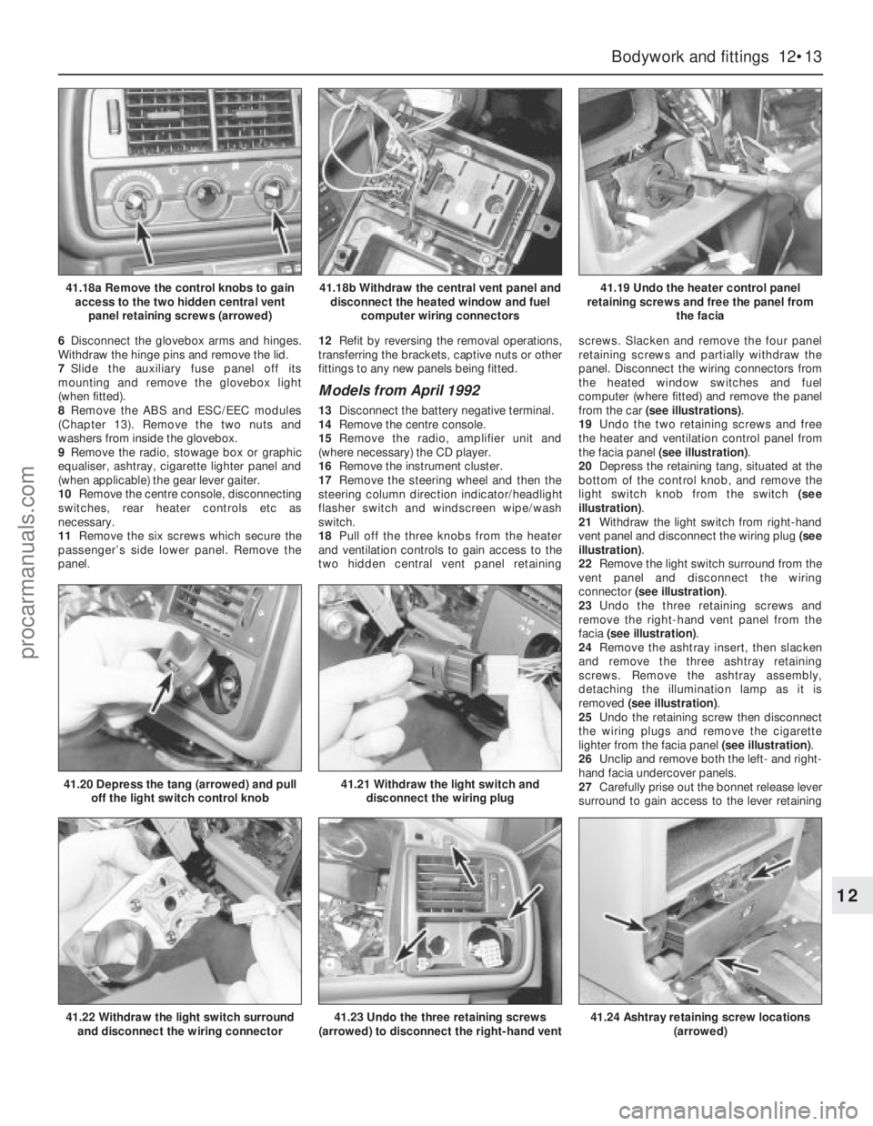
18Pull off the three knobs from the heater
and ventilation controls to gain access to the
two hidden central vent panel retainingscrews. Slacken and remove the four panel
retaining screws and partially withdraw the
panel. Disconnect the wiring connectors from
the heated window switches and fuel
computer (where fitted) and remove the panel
from the car (see illustrations).
19Undo the two retaining screws and free
the heater and ventilation control panel from
the facia panel (see illustration).
20Depress the retaining tang, situated at the
bottom of the control knob, and remove the
light switch knob from the switch (see
illustration).
21Withdraw the light switch from right-hand
vent panel and disconnect the wiring plug (see
illustration).
22Remove the light switch surround from the
vent panel and disconnect the wiring
connector (see illustration).
23Undo the three retaining screws and
remove the right-hand vent panel from the
facia (see illustration).
24Remove the ashtray insert, then slacken
and remove the three ashtray retaining
screws. Remove the ashtray assembly,
detaching the illumination lamp as it is
removed (see illustration).
25Undo the retaining screw then disconnect
the wiring plugs and remove the cigarette
lighter from the facia panel (see illustration).
26Unclip and remove both the left- and right-
hand facia undercover panels.
27Carefully prise out the bonnet release lever
surround to gain access to the lever retaining
Bodywork and fittings 12•13
12
41.18a Remove the control knobs to gain
access to the two hidden central vent
panel retaining screws (arrowed)41.18b Withdraw the central vent panel and
disconnect the heated window and fuel
computer wiring connectors41.19 Undo the heater control panel
retaining screws and free the panel from
the facia
41.22 Withdraw the light switch surround
and disconnect the wiring connector
41.20 Depress the tang (arrowed) and pull
off the light switch control knob41.21 Withdraw the light switch and
disconnect the wiring plug
41.23 Undo the three retaining screws
(arrowed) to disconnect the right-hand vent41.24 Ashtray retaining screw locations
(arrowed)
procarmanuals.com
Page 189 of 255
20When refitting, check the switch for
correct operation before refitting the shrouds
and steering wheel centre cover. When fitting
the shrouds, be careful not to trap the switch
rubber gaiter.
Models from April 1992
21Note that if access to the switch retaining
screws cannot be gained with the steering
wheel in position, then the steering wheel
must first be removed.
Windscreen wipe/wash switch
Models before April 1992
22Proceed as described in the previous sub-
section for the direction indicator switch.
Depending on equipment, the wipe/wash
switch may have more than one multi-plug
connected to it.
Models from April 1992
23Note that if access to the switch retaining
screws cannot be gained with the steering
wheel in position, then the steering wheel
must first be removed.
Door pillar switch (for courtesy
light)
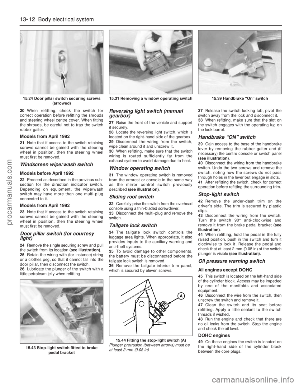
24Remove the single securing screw and pull
the switch from its location (see illustration).
25Retain the wiring with (for instance) string
or a clothes peg, so that it cannot fall into the
door pillar, then disconnect the switch.
26Lubricate the plunger of the switch with a
little petroleum jelly when refitting
Reversing light switch (manual
gearbox)
27Raise the front of the vehicle and support
it securely.
28Locate the reversing light switch, which is
located on the right-hand side of the gearbox.
29Disconnect the wiring from the switch,
wipe clean around it and unscrew it.
30When refitting, make sure that the switch
wiring is routed sufficiently far from the
exhaust system to avoid damage due to heat.
Window operating switch
31The window operating switch is removed
from the armrest or console in the same way
as the mirror control switch previously
described (see illustration).
Sliding roof switch
32Carefully prise the switch from the overhead
console using a thin-bladed screwdriver.
33Disconnect the multi-plug and remove the
switch.
Tailgate lock switch
34The tailgate lock switch controls the
luggage area lights. When appropriate, it also
provides inputs to the auxiliary warning and
anti-theft systems.
35To avoid damage to other components,
the battery must be disconnected before the
tailgate lock switch is removed.
36Remove the tailgate interior trim panel,
which is secured by eleven screws.37Release the switch locking tab, pivot the
switch away from the lock and disconnect it.
38When refitting, make sure that the slot on
the switch engages with the operating lug on
the lock barrel.
Handbrake “ON” switch
39Gain access to the base of the handbrake
lever by removing the rubber gaiter and (if
necessary) the centre console or switch panel
(see illustration).
40Disconnect the wiring from the handbrake
switch. Undo the two screws and remove the
switch, noting how the screws do not pass
through holes in the lever but engage in slots.
41After refitting the switch, check for correct
operation before refitting the surrounding trim.
Stop-light switch
42Remove the under-dash trim on the
driver’s side. The trim is secured by plastic
clips.
43Disconnect the wiring from the switch.
Turn the switch 90°anti-clockwise and
remove it from the brake pedal bracket (see
illustration).
44When refitting, hold the pedal in the fully
raised position, push in the switch and turn it
clockwise to lock it. Release the pedal and
check that at least 2 mm (0.08 in) of the switch
plunger is visible (see illustration).
Oil pressure warning switch
All engines except DOHC
45This switch is located on the left-hand side
of the cylinder block. Access may be impeded
by one of the manifolds and associated
equipment.
46Disconnect the wire from the switch, then
unscrew the switch and remove it.
47Clean the switch and its seat before
refitting. Apply a little sealant to the switch
threads if wished.
48Run the engine and check that there are
no oil leaks from the switch. Stop the engine
and check the oil level.
DOHC engines
49On these engines the switch is located on
the right-hand side of the cylinder block
between the core plugs.
13•12Body electrical system
15.24 Door pillar switch securing screws
(arrowed)
15.43 Stop-light switch fitted to brake
pedal bracket
15.44 Fitting the stop-light switch (A)
Plunger protrusion (between arrows) must be
at least 2 mm (0.08 in)
15.31 Removing a window operating switch15.39 Handbrake “On” switch
procarmanuals.com
Page 190 of 255
Heated rear window switch
Models before April 1992
50Remove the instrument panel surround,
which is secured by four screws.
51Carefully prise the switch from its location,
disconnect the multi-plug and remove it.
Models from April 1992
52Using a small flat-bladed screwdriver,
carefully prise the switch out of the centre
facia vent panel and disconnect the wiring
connector.
53On refitting, reconnect the wiring
connector and push the switch in until it clicks
into position.
Foglight switch(es)
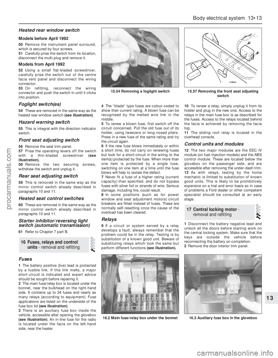
54These are removed in the same way as the
heated rear window switch (see illustration).
Hazard warning switch
55This is integral with the direction indicator
switch.
Front seat adjusting switch
56Remove the seat trim panel.
57Prise the operating levers off the switch
with a thin-bladed screwdriver (see
illustration).
58Remove the two securing screws,
withdraw the switch and unplug it.
Rear seat adjusting switch
59This is removed in the same way as the
mirror control switch already described in
paragraphs 10 and 11.
Heated seat control switches
60These are removed in the same way as the
mirror control switch already described in
paragraphs 10 and 11.
Starter inhibitor/reversing light
switch (automatic transmission)
61Refer to Chapter 7 part B.
Fuses
1The battery positive (live) lead is protected
by a fusible link. If this link melts, a major
short-circuit is indicated and expert advice
should be sought before repairing it.
2The main fuse/relay box is located under the
bonnet, near the bulkhead on the right-hand
side. It contains up to 24 fuses and nearly as
many relays (according to equipment). Fuse
applications are listed on the underside of the
fuse box lid (see illustration).
3There is an auxiliary fuse box inside the
vehicle, accessible after opening the glovebox
(see illustration). An in-line fuse for the radio
is located under the facia on the left-hand
side, near the heater.4The“blade” type fuses are colour-coded to
show their current rating. A blown fuse can be
recognised by the melted wire link in the
middle.
5To renew a blown fuse, first switch off the
circuit concerned. Pull the old fuse out of its
holder, using tweezers or long-nosed pliers.
Press in a new fuse of the same rating and try
the circuit again.
6If the new fuse blows immediately or within
a short time, do not carry on renewing fuses
but look for a short-circuit in the wiring to the
item(s) protected by the fuse. When more than
one item is protected by a single fuse,
switching on one item at a time until the fuse
blows will help to isolate the defect.
7Never fit a fuse of a higher rating (current
capacity) than specified, and do not bypass
fuses with silver foil or strands of wire. Serious
damage, including fire, could result.
8In some positions (such as for power
window and seat adjustment motors) circuit
breakers are fitted instead of fuses. These are
normally self-resetting once the cause of the
overload has been cleared.
Relays
9If a circuit or system served by a relay
develops a fault, always remember that the
problem could be in the relay. Testing is by
substitution of a known good unit. Beware of
substituting relays which look the same but
perform different functions(see illustration).10To renew a relay, simply unplug it from its
holder and plug in the new one. Access to the
relays in the main fuse box is as described for
the fuses. Access to the relays located behind
the facia is achieved by removing the facia
top.
11The sliding roof relay is located in the
overhead console.
Control units and modules
12The two major modules are the EEC IV
module (on fuel-injection models) and the ABS
control module. These are located below the
glovebox on the passenger side, and are
accessible after removing the under-dash trim.
13As with relays, testing by the home
mechanic is limited to substitution of known
good units. This is likely to be prohibitively
expensive on a trial and error basis so in case
of problems a Ford dealer or other competent
specialist should be consulted at an early
stage.
1Disconnect the battery negative lead and
unlock all the doors before starting work on
the central locking system. Make sure that the
keys are outside the vehicle before
reconnecting the battery on completion.
2Remove the door interior trim panel.
17Central locking motor -
removal and refitting
16Fuses, relays and control
units - removal and refitting
Body electrical system 13•13
13
15.54 Removing a foglight switch15.57 Removing the front seat adjusting
switch
16.2 Main fuse/relay box under the bonnet16.3 Auxiliary fuse box in the glovebox
procarmanuals.com
Page 195 of 255
Computer module and bulb
Models before April 1992
2Remove the instrument panel surround,
which is secured by four screws.
3Carefully pull the module from its location.
Release the multi-plug by pressing
downwards and disconnect it.
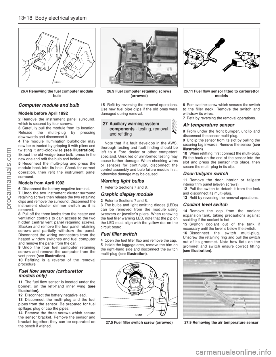
4The module illumination bulbholder may
now be extracted by gripping it with pliers and
twisting it anti-clockwise (see illustration).
Extract the old wedge base bulb, press in the
new one and refit the bulb and holder.
5Reconnect the multi-plug and press the
module back into its hole. Check for correct
operation, then refit the instrument panel
surround.
Models from April 1992
6Disconnect the battery negative terminal.
7Undo the two instrument cluster surround
retaining screws then release the two retaining
clips and remove the surround. Disconnect the
instrument cluster dimmer switch as it is
removed.
8Pull off the three knobs from the heater and
ventilation controls to gain access to the two
hidden central vent panel retaining screws.
Slacken and remove the four panel retaining
screws and partially withdraw the panel.
Disconnect the wiring connectors from the
heated window switches and fuel computer
and remove the panel from the car.
9Undo the four fuel computer retaining
screws and remove the computer from the
vent panel (see illustration).
10Refitting is a reverse of the removal
procedure.
Fuel flow sensor (carburettor
models only)
11The fuel flow sensor is located under the
bonnet, on the left-hand inner wing (see
illustration).
12Disconnect the battery negative lead.
13Disconnect the multi-plug and the fuel
pipes from the sensor. Be prepared for fuel
spillage; plug or cap the pipes.
14Remove the three screws which secure
the sensor bracket. Remove the sensor and
bracket together; they can be separated on
the bench if wished.15Refit by reversing the removal operations.
Use new fuel pipe clips if the old ones were
damaged during removal.
Note that if a fault develops in the AWS,
thorough testing and fault finding should be
left to a Ford dealer or other competent
specialist. Unskilled or uninformed testing may
cause further damage. When checking wires
or sensors for continuity, disconnect the
control assembly and bulb failure module first,
otherwise damage may be caused.
Warning light bulbs
1Refer to Sections 7 and 8.
Graphic display module
2Refer to Sections 7 and 8.
3The bulbs and light emitting diodes (LEDs)
can be removed from the module using
tweezers or jeweller’s pliers. When renewing
the fuel filler warning LED, note that the pip on
the LED must align with the yellow dot on the
circuit board.
Fuel filler switch
4Open the fuel filler flap and remove the cap.
5Inside the luggage area, remove the trim on
the right-hand side and disconnect the switch
multi-plug(see illustration).6Remove the screw which secures the switch
to the filler neck. Remove the switch and
withdraw its wires.
7Refit by reversing the removal operations.
Air temperature sensor
8From under the front bumper, unclip and
disconnect the sensor multi-plug.
9Unclip the sensor from its slot by pulling the
securing tag inwards. Remove the sensor (see
illustration).
10When refitting, first connect the multi-plug.
Fit the hook on the end of the sensor into the
slot and press the sensor into place, then
secure the multi-plug in its clip.
Door/tailgate switch
11Remove the door interior ortailgate
interior trim panel (eleven screws).
12Pull the switch to detach it from the lock
and disconnect its multi-plug.
13Refit by reversing the removal operations.
Coolant level switch
14Remove the cap from the coolant
expansion tank, taking precautions against
scalding if the coolant is hot.
15Syphon coolant out of the tank if
necessary until the level is below the switch.
16Disconnect the switch multi-plug.
Unscrew the retaining ring and pull the switch
out of its grommet. Note how flats on the
grommet and switch ensure correct fitting
(see illustration).
27Auxiliary warning system
components - testing, removal
and refitting
13•18Body electrical system
26.4 Renewing the fuel computer module
bulb
27.5 Fuel filler switch screw (arrowed)27.9 Removing the air temperature sensor
26.9 Fuel computer retaining screws
(arrowed)26.11 Fuel flow sensor fitted to carburettor
models
procarmanuals.com