coolant temperature FORD GRANADA 1985 Service Repair Manual
[x] Cancel search | Manufacturer: FORD, Model Year: 1985, Model line: GRANADA, Model: FORD GRANADA 1985Pages: 255, PDF Size: 14.98 MB
Page 4 of 255
1•3
1
Maintenance Schedule
Engine oil
SOHC:
With filter . . . . . . . . . . . . . . . . . . . . . . . . . . . . . .3.75 litres (6.6 pints)
DOHC:
With filter . . . . . . . . . . . . . . . . . . . . . . . . . . . . . . .4.5 litres (7.9 pints)
Without filter . . . . . . . . . . . . . . . . . . . . . . . . . . . . .4.0 litres (7.0 pints)
V6:
With filter . . . . . . . . . . . . . . . . . . . . . . . . . . . . . .4.25 litres (7.5 pints)
Cooling system
OHC . . . . . . . . . . . . . . . . . . . . . . . . . . . . . . . . . . . .8.0 litres (14.1 pints)
V6 . . . . . . . . . . . . . . . . . . . . . . . . . . . . . . . . . . . .8.5 litres (15.0 pints)
Fuel tank
All models . . . . . . . . . . . . . . . . . . . . . . . . . . . . .70 litres (15.4 gallons)
Manual gearbox
All models . . . . . . . . . . . . . . . . . . . . . . . . . . . . . .1.25 litres (2.2 pints)
Automatic transmission
All models (from dry) . . . . . . . . . . . . . . . . . . . . . . .8.5 litres (15.0 pints)
Final drive
7 inch crownwheel . . . . . . . . . . . . . . . . . . . . . . . . . .0.9 litres (1.6 pints)
7.5 inch crownwheel . . . . . . . . . . . . . . . . . . . . . . . . .1.3 litres (2.3 pints)
Power steering
OHC . . . . . . . . . . . . . . . . . . . . . . . . . . . . . . . . . . . .0.65 litres (1.1 pints)
V6 . . . . . . . . . . . . . . . . . . . . . . . . . . . . . . . . . . . .0.75 litres (1.3 pints)
Capacities
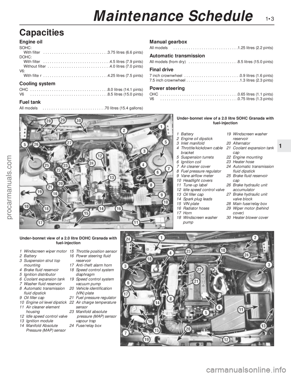
1 Battery
2 Engine oil dipstick
3 Inlet manifold
4 Throttle/kickdown cable
bracket
5 Suspension turrets
6 Ignition coil
7 Air cleaner cover
8 Fuel pressure regulator
9 Vane airflow meter
10 Headlight covers
11 Tune-up label
12 Idle speed control valve
13 Oil filler cap
14 Spark plug leads
15 VIN plate
16 Radiator hoses
17 Horn
18 Windscreen washer
pump19 Windscreen washer
reservoir
20 Alternator
21 Coolant expansion tank
cap
22 Engine mounting
23 Heater hose
24 Automatic transmission
fluid dipstick
25 Brake fluid reservoir
cap
26 Brake hydraulic unit
accumulator
27 Brake hydraulic unit
valve block
28 Main fuse/relay box
29 Wiper motor (behind
cover)
30 Heater blower cover
1 Windscreen wiper motor
2 Battery
3 Suspension strut top
mounting
4 Brake fluid reservoir
5 Ignition distributor
6 Coolant expansion tank
7 Washer fluid reservoir
8 Automatic transmission
fluid dipstick
9 Oil filler cap
10 Engine oil level dipstick
11 Air cleaner element
housing
12 Idle speed control valve
13 Ignition module
14 Manifold Absolute
Pressure (MAP) sensor15 Throttle position sensor
16 Power steering fluid
reservoir
17 Anti-theft alarm horn
18 Speed control system
diaphragm
19 Speed control system
vacuum pump
20 Vehicle identification
(VIN) plate
21 Fuel pressure regulator
22 Air charge temperature
sensor
23 Manifold absolute
pressure (MAP) sensor
vapour trap
24 Fuse/relay boxUnder-bonnet view of a 2.0 litre SOHC Granada with
fuel-injection
Under-bonnet view of a 2.0 litre DOHC Granada with
fuel-injection
procarmanuals.com
Page 11 of 255
1Firmly apply the handbrake, then jack up the
front and rear of the car and support it
securely on axle stands (see “Jacking”).
2For a quick check, the front brake disc pads
can be inspected without removing the front
wheels, using a mirror and a torch through the
aperture in the rear face of the caliper. If any
one pad is worn down to the minimum
specified, all four pads (on both front wheels)
must be renewed.
3It is necessary to remove the rear wheels in
order to inspect the rear pads. The pads can
be viewed through the top of the caliper after
removing the spring clip. If any one pad is
worn down to the minimum specified, all four
pads (on both rear wheels) must be renewed.
4For a comprehensive check, the brake pads
should be removed and cleaned. The
operation of the caliper can then also be
checked, and the condition of the brake discs
can be fully examined on both sides. Refer to
Chapter 10 for further information.
5At the same interval, check the function of
the brake fluid level warning light. Chock the
wheels, release the handbrake and switch on
the ignition. Unscrew and raise the brake fluid
reservoir cap whilst an assistant observes the
warning light: it should come on as the level
sensor is withdrawn from the fluid. Refit the
cap.
6On completion, refit the wheels and lower
the car to the ground.
1Visually inspect the engine joint faces,
gaskets and seals for any signs of water or oil
leaks. Pay particular attention to the areas
around the rocker cover, cylinder head, oil
filter and sump joint faces. Bear in mind that
over a period of time some very slight seepage
from these areas is to be expected but what
you are really looking for is any indication of a
serious leak. Should a leak be found, renew
the offending gasket or oil seal by referring to
the appropriate Chapter(s) in this manual.
2Similarly, check the transmission for oil
leaks, and investigate and rectify and
problems found.
3Check the security and condition of all the
engine related pipes and hoses. Ensure that all
cable-ties or securing clips are in place and in
good condition. Clips which are broken or
missing can lead to chafing of the hoses,
pipes or wiring which could cause more
serious problems in the future.
4Carefully check the condition of all coolant,
fuel and brake hoses. Renew any hose which
is cracked, swollen or deteriorated. Cracks will
show up better if the hose is squeezed. Pay
close attention to the hose clips that secure
the hoses to the system components. Hoseclips can pinch and puncture hoses, resulting
in leaks. If wire type hose clips are used, it
may be a good idea to replace them with
screw-type clips.
5With the vehicle raised, inspect the fuel tank
and filler neck for punctures, cracks and other
damage. The connection between the filler neck
and tank is especially critical. Sometimes a
rubber filler neck or connecting hose will leak due
to loose retaining clamps or deteriorated rubber.
6Similarly, inspect all brake hoses and metal
pipes. If any damage or deterioration is
discovered, do not drive the vehicle until the
necessary repair work has been carried out.
Renew any damaged sections of hose or pipe.
7Carefully check all rubber hoses and metal
fuel lines leading away from the petrol tank.
Check for loose connections, deteriorated
hoses, crimped lines and other damage. Pay
particular attention to the vent pipes and
hoses which often loop up around the filler
neck and can become blocked or crimped.
Follow the lines to the front of the vehicle
carefully inspecting them all the way. Renew
damaged sections as necessary.
8From within the engine compartment, check
the security of all fuel hose attachments and
pipe unions, and inspect the fuel hoses and
vacuum hoses for kinks, chafing and
deterioration.
9Where applicable, check the condition of
the oil cooler hoses and pipes.
10Check the condition of all exposed wiring
harnesses.
11Also check the engine and transmission
components for signs of fluid leaks.
Periodically check the belts for fraying or
other damage. If evident, renew the belt.
If the belts become dirty, wipe them with a
damp cloth using a little detergent only.
Check the tightness of the anchor bolts and
if they are ever disconnected, make quite sure
that the original sequence of fitting of washers,
bushes and anchor plates is retained.With the vehicle raised on a hoist or
supported on axle stands (see “Jacking”),
check the exhaust system for signs of leaks,
corrosion or damage and check the rubber
mountings for condition and security. Where
damage or corrosion are evident, renew the
system complete or in sections, as applicable,
using the information given in Chapter 4.
With the wheels on the ground, slacken
each wheel nut by a quarter turn, then
retighten it immediately to the specified
torque.
Remove and clean the oil filler cap of any
sludge build-up using paraffin.
Inspect the vent hose for blockage or
damage. A blocked hose can cause a build-up
of crankcase pressure, which in turn can
cause oil leaks.
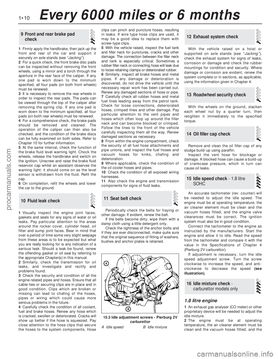
An accurate tachometer (rev. counter) will
be needed to adjust the idle speed. The
engine must be at operating temperature, the
air cleaner element must be clean and the
vacuum hoses fitted, and the engine valve
clearances must be correct. The ignition
system must also be in good condition.
Connect the tachometer to the engine as
instructed by the manufacturers. Start the
engine and allow it to idle. Read the speed
from the tachometer and compare it with the
value in the Specifications of Chapter 4
(Pierburg 2V carburettor).
If adjustment is necessary, turn the idle
speed adjustment screw. Turn the screw
clockwise to increase the speed, and anti-
clockwise to decrease the speed (see
illustration).
1.8 litre engine
1An exhaust gas analyser (CO meter) or other
proprietary device will be needed to adjust the
idle mixture.
2The engine must be at operating
temperature, the air cleaner element must be
clean and the vacuum hoses fitted, and the
16Idle mixture check -
carburettor models only
15Idle speed check - 1.8 litre
SOHC
14Oil filler cap check
13Roadwheel security check
12Exhaust system check
11Seat belt check10Fluid leak check
9Front and rear brake pad
check
1•10Every 6000 miles or 6 months
15.3 Idle adjustment screws - Pierburg 2V
carburettor
A Idle speedB Idle mixture
procarmanuals.com
Page 21 of 255
12Place a piece of wood in the caliper jaws
to limit piston travel. Keep your fingers clear of
the piston. Have the assistant depress the
brake pedal gentlyin order to move the
caliper piston out.
13With the pedal held depressed, slacken
the bleed screw on the right-hand caliper and
again depress the piston. Tighten the bleed
screw when the piston is retracted. The pedal
can now be released.
14Disconnect the bleed tube. Refit the right-hand brake pad and caliper.
15Remove the left-hand caliper and inboard
pad again. Carry out the operations described
in paragraphs 10 to 14 on the left-hand
caliper.
16Bleed the rear brakes as described in
Chapter 10.
17Refit the front wheels, lower the vehicle
and tighten the wheel nuts.
18Pump the brake pedal to bring the pads
up to the discs, then make a final check of thehydraulic fluid level. Top-up and refit the
reservoir cap.
Camshaft drivebelt renewal is
recommended as a precautionary measure.
Refer to Chapter 2, Part A, Sections 13 and 45
for the full renewal procedure.
45Camshaft drivebelt renewal -
SOHC engines
1Before proceeding, note the precautions
given in Chapter 3, Section 1.
2Disconnect the battery negative lead.
3Remove the expansion tank cap. Take
precautions against scalding if the system is
hot.
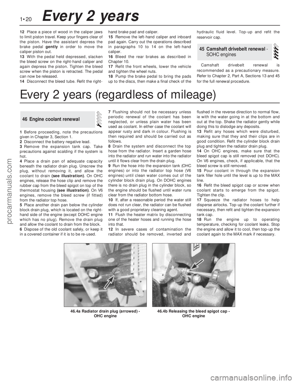
4Place a drain pan of adequate capacity
beneath the radiator drain plug. Unscrew the
plug, without removing it, and allow the
coolant to drain (see illustration). On OHC
engines, release the hose clip and remove the
rubber cap from the bleed spigot on top of the
thermostat housing (see illustration). On V6
engines, remove the bleed screw (if fitted)
from the radiator top hose.
5Place another drain pan below the cylinder
block drain plug, which is located on the right-
hand side of the engine (except DOHC engine
which has no plug). Remove the drain plug
and allow the coolant to drain from the block.
6Dispose of the old coolant safely, or keep it
in a covered container if it is to be re-used.7Flushing should not be necessary unless
periodic renewal of the coolant has been
neglected, or unless plain water has been
used as coolant. In either case the coolant will
appear rusty and dark in colour. Flushing is
then required and should be carried out as
follows.
8Drain the system and disconnect the top
hose from the radiator. Insert a garden hose
into the radiator and run water into the radiator
until it flows clear from the drain plug.
9Run the hose into the expansion tank (OHC
engines) or into the radiator top hose (V6
engines) until clean water comes out of the
cylinder block drain plug. On DOHC engines
there is no drain plug in the cylinder block, so
the engine should be flushed until water runs
clear from the radiator bottom hose.
10If, after a reasonable period the water still
does not run clear, the radiator can be flushed
with a good proprietary cleaning agent.
11Flush the heater matrix by disconnecting
one of the heater hoses and running the hose
into that.
12In severe cases of contamination the
radiator should be removed, inverted andflushed in the reverse direction to normal flow,
ie with the water going in at the bottom and
out at the top. Shake the radiator gently while
doing this to dislodge any deposits.
13Refit any hoses which were disturbed,
making sure that they and their clips are in
good condition. Refit the cylinder block drain
plug and tighten the radiator drain plug.
14On OHC engines, make sure that the
bleed spigot cap is still removed (not DOHC).
On V6 engines, check, if applicable, that the
bleed screw is still removed.
15Pour coolant in through the expansion
tank filler hole until the level is up to the MAX
line.
16Refit the bleed spigot cap or screw when
coolant starts to emerge from the spigot.
Tighten the clip.
17Squeeze the radiator hoses to help
disperse airlocks. Top-up the coolant further if
necessary, then refit and tighten the expansion
tank cap.
18Run the engine up to operating
temperature, checking for coolant leaks. Stop
the engine and allow it to cool, then top-up the
coolant again to the MAX mark if necessary.
46Engine coolant renewal
1•20Every 2 years
46.4b Releasing the bleed spigot cap -
OHC engine46.4a Radiator drain plug (arrowed) -
OHC engine
Every 2 years (regardless of mileage)
procarmanuals.com
Page 43 of 255
See Chapter 1, Section 23.
1Make a final check to ensure that everything
has been reconnected to the engine and that no
rags or tools have been left in the engine bay.
2Check that oil and coolant levels are
correct.
3Start the engine. This may take a little longer
than usual as fuel is pumped up to the engine.
4Check that the oil pressure light goes out
when the engine starts.
5Run the engine at a fast tickover and check
for leaks of oil, fuel and coolant. Also check
power steering and transmission fluid cooler
unions, when applicable. Some smoke and
odd smells may be experienced as assembly
lubricant burns off the exhaust manifold and
other components.6Bring the engine to operating temperature.
Check the ignition timing then adjust the idle
speed (if applicable) and mixture.
7Stop the engine and allow it to cool, then re-
check the oil and coolant levels.
8If new bearings, pistons etc have been
fitted, the engine should be run in at reduced
speeds and loads for the first 500 miles (800
km) or so. It is beneficial to change the engine
oil and filter after this mileage.
1When engine performance is down, or if
misfiring occurs which cannot be attributed to
the ignition or fuel system, a compression test
can provide diagnostic clues. If the test is
performed regularly it can give warning of
trouble before any other symptoms become
apparent.
2The engine must be at operating
temperature, the battery must be fully charged
and the spark plugs must be removed. The
services of an assistant will also be required.
3Disable the ignition system by dismantlingthe coil LT feed. Fit the compression tester to
No 1 spark plug hole. (The type of tester which
screws into the spark plug hole is to be
preferred.)
4Have the assistant hold the throttle wide
open and crank the engine on the starter.
Record the highest reading obtained on the
compression tester.
5Repeat the test on the remaining cylinders,
recording the pressure developed in each.
6Desired pressures are given in the
Specifications. If the pressure in any cylinder
is low, introduce a teaspoonful of clean engine
oil into the spark plug hole and repeat the test.
7If the addition of oil temporarily improves
the compression pressure, this indicates that
bore or piston wear was responsible for the
pressure loss. No improvement suggests that
leaking or burnt valves, or a blown head
gasket, may be to blame.
8A low reading from two adjacent cylinders is
almost certainly due to the head gasket
between them having blown.
9On completion of the test, refit the spark
plugs and reconnect the coil LT feed.
52Compression test -
description and interpretation
51Initial start-up after overhaul
or major repair
50Valve clearances - checking
and adjustment
2A•20SOHCengines
procarmanuals.com
Page 47 of 255
manifold. Piston blow-by gases are drawn
through the oil separator and the vent valve to
the inlet manifold. The blow-by gases are then
drawn into the engine together with the fuel/air
mixture. Refer to Chapter 1 for maintenance of
the system.
The following operations can be carried out
without removing the engine from the vehicle.
a)Removal of the camshafts.
b)Removal and servicing of the cylinder
head.
c)Removal of the timing chain and
sprockets.
d)Removal of the oil pump.
e)Removal of the sump.
f)Removal of the pistons and connecting
rods.
g)Removal of the big-end bearings.
h)Removal of the engine mountings.
i)Removal of the clutch and flywheel.
j)Removal of the crankshaft front and rear
oil seals.
The following operations can only be carried
out after removing the engine from the vehicle.
a)Removal of the crankshaft main bearings.
b)Removal of the crankshaft.
Note: A hoist and lifting tackle will be required
to lift the engine out of the vehicle.
1Disconnect the battery negative lead.
2Remove the bonnet.
3On carburettor models, remove the air cleaner.
4On fuel-injection models, remove the air
inlet hose, plenum chamber and air cleaner lid
as an assembly.
5Disconnect the breather hose from the
camshaft cover, and unscrew the bolt
securing the hose support bracket to the left-
hand side of the cylinder head (see
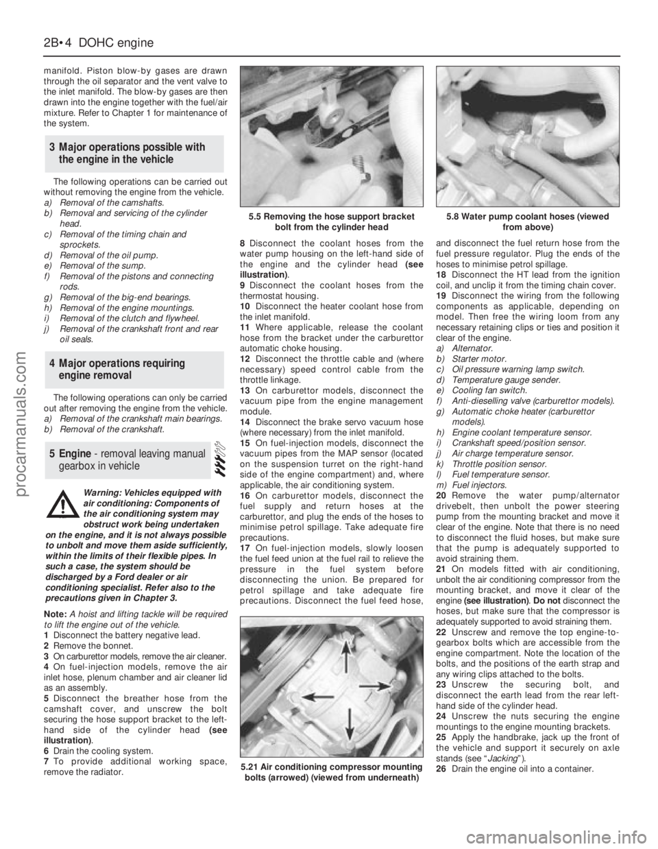
illustration).
6Drain the cooling system.
7To provide additional working space,
remove the radiator.8Disconnect the coolant hoses from the
water pump housing on the left-hand side of
the engine and the cylinder head (see
illustration).
9Disconnect the coolant hoses from the
thermostat housing.
10Disconnect the heater coolant hose from
the inlet manifold.
11Where applicable, release the coolant
hose from the bracket under the carburettor
automatic choke housing.
12Disconnect the throttle cable and (where
necessary) speed control cable from the
throttle linkage.
13On carburettor models, disconnect the
vacuum pipe from the engine management
module.
14Disconnect the brake servo vacuum hose
(where necessary) from the inlet manifold.
15On fuel-injection models, disconnect the
vacuum pipes from the MAP sensor (located
on the suspension turret on the right-hand
side of the engine compartment) and, where
applicable, the air conditioning system.
16On carburettor models, disconnect the
fuel supply and return hoses at the
carburettor, and plug the ends of the hoses to
minimise petrol spillage. Take adequate fire
precautions.
17On fuel-injection models, slowly loosen
the fuel feed union at the fuel rail to relieve the
pressure in the fuel system before
disconnecting the union. Be prepared for
petrol spillage and take adequate fire
precautions. Disconnect the fuel feed hose,and disconnect the fuel return hose from the
fuel pressure regulator. Plug the ends of the
hoses to minimise petrol spillage.
18Disconnect the HT lead from the ignition
coil, and unclip it from the timing chain cover.
19Disconnect the wiring from the following
components as applicable, depending on
model. Then free the wiring loom from any
necessary retaining clips or ties and position it
clear of the engine.
a)Alternator.
b)Starter motor.
c)Oil pressure warning lamp switch.
d)Temperature gauge sender.
e)Cooling fan switch.
f)Anti-dieselling valve (carburettor models).
g)Automatic choke heater (carburettor
models).
h)Engine coolant temperature sensor.
i)Crankshaft speed/position sensor.
j)Air charge temperature sensor.
k)Throttle position sensor.
l)Fuel temperature sensor.
m)Fuel injectors.
20Remove the water pump/alternator
drivebelt, then unbolt the power steering
pump from the mounting bracket and move it
clear of the engine. Note that there is no need
to disconnect the fluid hoses, but make sure
that the pump is adequately supported to
avoid straining them.
21On models fitted with air conditioning,
unbolt the air conditioning compressor from the
mounting bracket, and move it clear of the
engine (see illustration). Do notdisconnect the
hoses, but make sure that the compressor is
adequately supported to avoid straining them.
22Unscrew and remove the top engine-to-
gearbox bolts which are accessible from the
engine compartment. Note the location of the
bolts, and the positions of the earth strap and
any wiring clips attached to the bolts.
23Unscrew the securing bolt, and
disconnect the earth lead from the rear left-
hand side of the cylinder head.
24Unscrew the nuts securing the engine
mountings to the engine mounting brackets.
25Apply the handbrake, jack up the front of
the vehicle and support it securely on axle
stands (see “Jacking”).
26Drain the engine oil into a container.
5Engine - removal leaving manual
gearbox in vehicle
4Major operations requiring
engine removal
3Major operations possible with
the engine in the vehicle
2B•4DOHCengine
5.5 Removing the hose support bracket
bolt from the cylinder head5.8 Water pump coolant hoses (viewed
from above)
5.21 Air conditioning compressor mounting
bolts (arrowed) (viewed from underneath)
Warning: Vehicles equipped with
air conditioning: Components of
the air conditioning system may
obstruct work being undertaken
on the engine, and it is not always possible
to unbolt and move them aside sufficiently,
within the limits of their flexible pipes. In
such a case, the system should be
discharged by a Ford dealer or air
conditioning specialist. Refer also to the
precautions given in Chapter 3.
procarmanuals.com
Page 68 of 255
meters and air inlet trunking. Also remove the
oil filler cap, which is connected to the
trunking by a crankcase ventilation hose.
5Release the securing clips and bolts and
remove the upper half of the fan shroud.
6Drain the cooling system and remove the
radiator.
7Disconnect the heater hoses from the
heater matrix and from the coolant outlet.
Unclip the hoses.
8Remove the fan and viscous clutch (where
fitted).
9Disconnect the following wiring:
a)Alternator
b)Temperature gauge sender
c)Engine management temperature sensor
d)Oil pressure switch
e)Idle speed control valve
f)Throttle position sensor
g)Injector nut-harness
h)Distributor multi-plug
i)Distributor-to-coil HT lead
10Disconnect the throttle cable. When
applicable, also disconnect the downshaft
cable or switch.
11Depressurise the fuel system and
disconnect the fuel supply and return lines
(see Chapter 4).
12Remove the steering pump and air
conditioning compressor drivebelts (as
applicable). Unbolt the steering pump and
compressor, move them aside within the limitsof their flexible hoses and support them by
wiring them to adjacent components.
13Remove the distributor cap and rotor.
14Remove the starter motor.
15Drain the engine oil. Unscrew the oil filter
with a strap or chain wrench and remove it; be
prepared for oil spillage.
16On manual gearbox models, disconnect
the clutch cable from the release lever.
17Unbolt the exhaust pipes from the
manifolds.
18On automatic transmission models, unbolt
the torque converter from the driveplate.
19Attach lifting tackle to the engine. If no
lifting eyes are fitted, pass ropes or chains
round the exhaust manifolds.
20Take the weight of the engine, then
remove the single nut on each side which
holds engine bearer to its mountings.
21From under the vehicle unbolt the engine
adapter plate from the bellhousing.
22Remove the engine-to-bellhousing bolts.
Also disconnect or unclip the battery negative
lead, the starter motor lead and the heat
shield.
23Support the transmission, preferably with
a trolley jack.
24Check that nothing has been overlooked,
then raise the engine and draw it forwards
clear of the transmission input shaft. Do not
allow the weight of the engine to hang on the
shaft, and do not lift the transmission by it.25With automatic transmission, make sure
that the torque converter stays engaged with
the oil pump in the transmission as the engine
is withdrawn.
26Lift the engine out of the engine bay and
take it to the bench.
2.4 & 2.9 litre engines
27The removal operations for these engines
are essentially as described for the 2.8 litre
version. Note the following points.
Coolant hoses
28Remove the hoses which run between the
thermostat housing and the water pump, and
the cooling system expansion tank.
29Remove the heater hoses which run
between the thermostat housing or coolant
distribution pipe and oil cooler (where fitted).
Vacuum hoses
30Disconnect the hose from the fuel
pressure regulator.
31Disconnect the hose from the plenum
chamber.
32Disconnect the hose from the throttle valve.
33Disconnect the hose from the T-piece
connector.
V6 engines 2C•7
2C
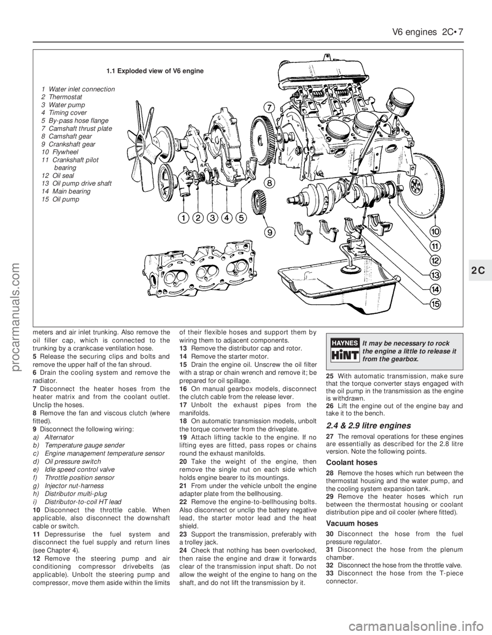
1.1 Exploded view of V6 engine
1 Water inlet connection
2 Thermostat
3 Water pump
4 Timing cover
5 By-pass hose flange
7 Camshaft thrust plate
8 Camshaft gear
9 Crankshaft gear
10 Flywheel
11 Crankshaft pilot
bearing
12 Oil seal
13 Oil pump drive shaft
14 Main bearing
15 Oil pump
It may be necessary to rock
the engine a little to release it
from the gearbox.
procarmanuals.com
Page 69 of 255
Other items
34Disconnect the throttle cable from the
operating lever and bracket.
35Disconnect the right-hand exhaust
downpipe from the manifold then remove the
starter motor, the oil filter, and disconnect the
left-hand exhaust downpipe, in that order.
Refer to Part A, Section 8, paragraphs 1 to 8
of this Chapter.
Cylinder head bolts on the V6 engine may
be conventional (hexagon-headed) or Torx
type. The appropriate Torx key will be needed
to deal with the latter.
Before dismantling the engine into its main
components, the following ancillaries can be
removed. The actual items removed, and the
sequence of removal, will depend on the work
to be done.
Distributor and bracket
Spark plugs
Inlet manifold and associated items
Exhaust manifolds
Clutch
Alternator and bracket
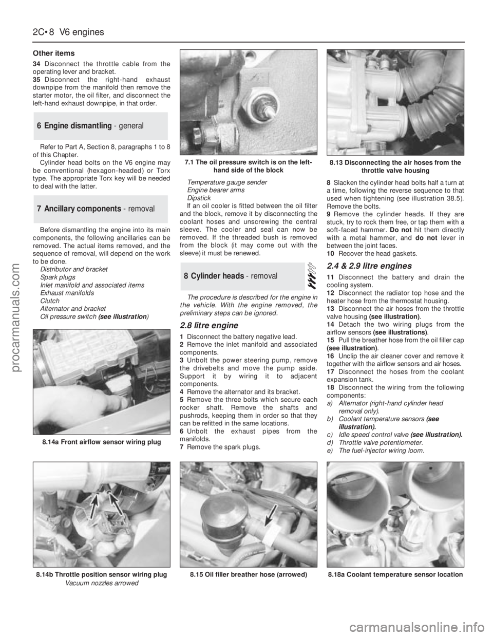
Oil pressure switch(see illustration) Temperature gauge sender
Engine bearer arms
Dipstick
If an oil cooler is fitted between the oil filter
and the block, remove it by disconnecting the
coolant hoses and unscrewing the central
sleeve. The cooler and seal can now be
removed. If the threaded bush is removed
from the block (it may come out with the
sleeve) it must be renewed.
The procedure is described for the engine in
the vehicle. With the engine removed, the
preliminary steps can be ignored.
2.8 litre engine
1Disconnect the battery negative lead.
2Remove the inlet manifold and associated
components.
3Unbolt the power steering pump, remove
the drivebelts and move the pump aside.
Support it by wiring it to adjacent
components.
4Remove the alternator and its bracket.
5Remove the three bolts which secure each
rocker shaft. Remove the shafts and
pushrods, keeping them in order so that they
can be refitted in the same locations.
6Unbolt the exhaust pipes from the
manifolds.
7Remove the spark plugs.8Slacken the cylinder head bolts half a turn at
a time, following the reverse sequence to that
used when tightening (see illustration 38.5).
Remove the bolts.
9Remove the cylinder heads. If they are
stuck, try to rock them free, or tap them with a
soft-faced hammer. Do nothit them directly
with a metal hammer, and do notlever in
between the joint faces.
10Recover the head gaskets.
2.4 & 2.9 litre engines
11Disconnect the battery and drain the
cooling system.
12Disconnect the radiator top hose and the
heater hose from the thermostat housing.
13Disconnect the air hoses from the throttle
valve housing (see illustration).
14Detach the two wiring plugs from the
airflow sensors (see illustrations).
15Pull the breather hose from the oil filler cap
(see illustration).
16Unclip the air cleaner cover and remove it
together with the airflow sensors and air hoses.
17Disconnect the hoses from the coolant
expansion tank.
18Disconnect the wiring from the following
components:
a)Alternator (right-hand cylinder head
removal only).
b)Coolant temperature sensors(see
illustration).
c)Idle speed control valve (see illustration).
d)Throttle valve potentiometer.
e)The fuel-injector wiring loom.8Cylinder heads - removal
7Ancillary components - removal
6Engine dismantling - general
2C•8V6 engines
7.1 The oil pressure switch is on the left-
hand side of the block
8.14b Throttle position sensor wiring plug
Vacuum nozzles arrowed
8.14a Front airflow sensor wiring plug
8.15 Oil filler breather hose (arrowed)8.18a Coolant temperature sensor location
8.13 Disconnecting the air hoses from the
throttle valve housing
procarmanuals.com
Page 70 of 255
19Disconnect the wiring connectors from the
ignition distributor and the fuel temperature
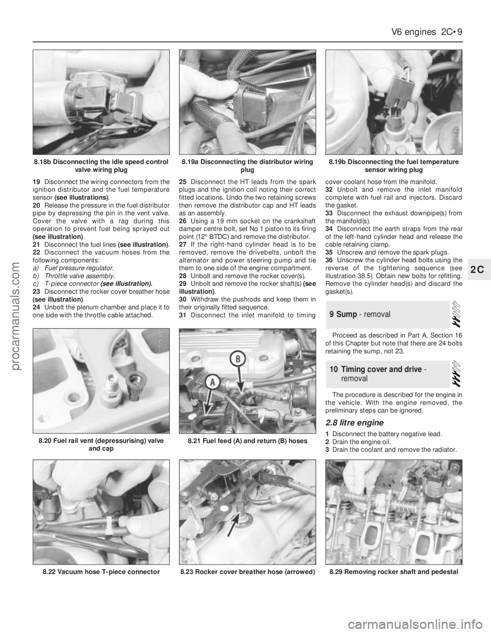
sensor (see illustrations).
20Release the pressure in the fuel distributor
pipe by depressing the pin in the vent valve.
Cover the valve with a rag during this
operation to prevent fuel being sprayed out
(see illustration).
21Disconnect the fuel lines (see illustration).
22Disconnect the vacuum hoses from the
following components:
a)Fuel pressure regulator.
b)Throttle valve assembly.
c)T-piece connector (see illustration).
23Disconnect the rocker cover breather hose
(see illustration).
24Unbolt the plenum chamber and place it to
one side with the throttle cable attached.25Disconnect the HT leads from the spark
plugs and the ignition coil noting their correct
fitted locations. Undo the two retaining screws
then remove the distributor cap and HT leads
as an assembly.
26Using a 19 mm socket on the crankshaft
damper centre bolt, set No 1 piston to its firing
point (12°BTDC) and remove the distributor.
27If the right-hand cylinder head is to be
removed, remove the drivebelts, unbolt the
alternator and power steering pump and tie
them to one side of the engine compartment.
28Unbolt and remove the rocker cover(s).
29Unbolt and remove the rocker shaft(s) (see
illustration).
30Withdraw the pushrods and keep them in
their originally fitted sequence.
31Disconnect the inlet manifold to timingcover coolant hose from the manifold.
32Unbolt and remove the inlet manifold
complete with fuel rail and injectors. Discard
the gasket.
33Disconnect the exhaust downpipe(s) from
the manifold(s).
34Disconnect the earth straps from the rear
of the left-hand cylinder head and release the
cable retaining clamp.
35Unscrew and remove the spark plugs.
36Unscrew the cylinder head bolts using the
reverse of the tightening sequence (see
illustration 38.5). Obtain new bolts for refitting.
Remove the cylinder head(s) and discard the
gasket(s).
Proceed as described in Part A, Section 16
of this Chapter but note that there are 24 bolts
retaining the sump, not 23.
The procedure is described for the engine in
the vehicle. With the engine removed, the
preliminary steps can be ignored.
2.8 litre engine
1Disconnect the battery negative lead.
2Drain the engine oil.
3Drain the coolant and remove the radiator.
10Timing cover and drive -
removal
9Sump - removal
V6 engines 2C•9
2C
8.18b Disconnecting the idle speed control
valve wiring plug8.19a Disconnecting the distributor wiring
plug8.19b Disconnecting the fuel temperature
sensor wiring plug
8.22 Vacuum hose T-piece connector
8.20 Fuel rail vent (depressurising) valve
and cap8.21 Fuel feed (A) and return (B) hoses
8.23 Rocker cover breather hose (arrowed)8.29 Removing rocker shaft and pedestal
procarmanuals.com
Page 81 of 255
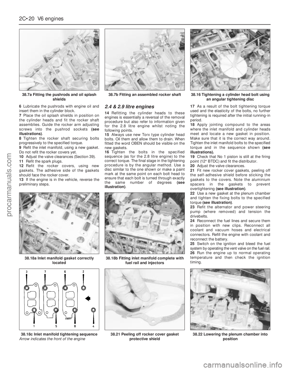
6Lubricate the pushrods with engine oil and
insert them in the cylinder block.
7Place the oil splash shields in position on
the cylinder heads and fit the rocker shaft
assemblies. Guide the rocker arm adjusting
screws into the pushrod sockets (see
illustrations).
8Tighten the rocker shaft securing bolts
progressively to the specified torque.
9Refit the inlet manifold, using a new gasket.
Do not refit the rocker covers yet.
10Adjust the valve clearances (Section 39).
11Refit the spark plugs.
12Refit the rocker covers, using new
gaskets. The adhesive side of the gaskets
should face the rocker cover.
13If the engine is in the vehicle, reverse the
preliminary steps.2.4 & 2.9 litre engines
14Refitting the cylinder heads to these
engines is essentially a reversal of the removal
procedure but also refer to information given
for the 2.8 litre engine whilstnoting the
following points.
15Always use new Torx type cylinder head
bolts. Oil them and allow them to drain. When
fitted the word OBEN should be visible on the
new gaskets.
16Tighten the bolts in the specified
sequence (as for the 2.8 litre engine) to the
correct torque. The final stage in the tightening
procedure is by the angular method. Use a
disc similar to the one shown or make a paint
mark at the same point on each bolt head to
ensure that each bolt is turned through exactly
the same number of degrees (see
illustration).17As a result of the bolt tightening torque
used and the elasticity of the bolts, no further
tightening is required after the initial running-in
period.
18Apply jointing compound to the areas
where the inlet manifold and cylinder heads
meet and locate a new gasket in position.
Make sure that it is the correct way around.
Tighten the inlet manifold bolts to the specified
torque and in the sequence shown (see
illustrations).
19Check that No 1 piston is still at the firing
point (12°BTDC) and fit the distributor.
20Adjust the valve clearances.
21Fit new rocker cover gaskets, peeling off
the self-adhesive shield before sticking the
gaskets to the covers. Note the aluminium
spacers in the gaskets to prevent
overtightening (see illustration).
22Use a new gasket at the plenum chamber
and tighten the fixing bolts to the specified
torque (see illustration).
23Refit the alternator and power steering
pump (where removed) and tension the
drivebelts.
24Reconnect the fuel lines and secure them
in position with new clips. Reconnect all
coolant and vacuum hoses and electrical
connectors. Refill the engine with coolant and
reconnect the battery.
25Switch on the ignition and bleed the fuel
system by operating the vent valve on the fuel rail.
26Run the engine up to normal operating
temperature and then check the ignition
timing.
2C•20V6 engines
38.7a Fitting the pushrods and oil splash
shields
38.18a Inlet manifold gasket correctly
located38.18b Fitting inlet manifold complete with
fuel rail and injectors
38.22 Lowering the plenum chamber into
position38.18c Inlet manifold tightening sequence
Arrow indicates the front of the engine38.21 Peeling off rocker cover gasket
protective shield
38.7b Fitting an assembled rocker shaft38.16 Tightening a cylinder head bolt using
an angular tightening disc
procarmanuals.com
Page 82 of 255
27The inlet manifold bolts should be
retightened to the specified torque in the correct
sequence. This will mean disconnecting the air
hoses from the throttle valve housing, the
vacuum hose from the left-hand rocker cover,
and the wiring connector from the idle speed
control valve and throttle valve potentiometer.
Remove the plenum chamber, place it to one
side, then release the fuel rail bolts but do not
disconnect the fuel pipes. It may also be
necessary to remove the distributor again to
gain access to one of the bolts.
See Chapter 1, Section 23.
1Refer to Section 7 and refit the items listed.
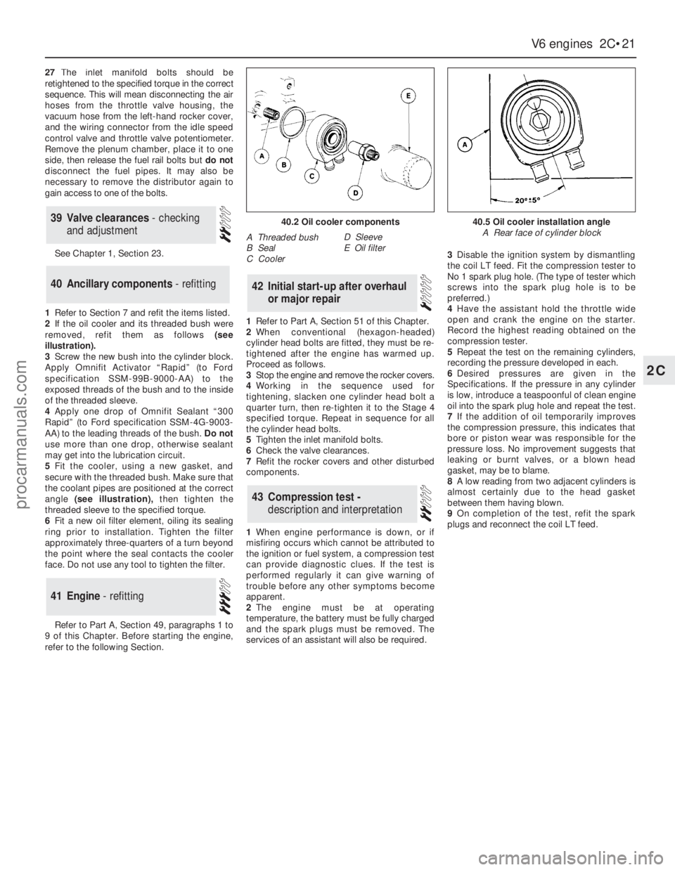
2If the oil cooler and its threaded bush were
removed, refit them as follows (see
illustration).
3Screw the new bush into the cylinder block.
Apply Omnifit Activator “Rapid” (to Ford
specification SSM-99B-9000-AA) to the
exposed threads of the bush and to the inside
of the threaded sleeve.
4Apply one drop of Omnifit Sealant “300
Rapid” (to Ford specification SSM-4G-9003-
AA) to the leading threads of the bush.Do not
use more than one drop, otherwise sealant
may get into the lubrication circuit.
5Fit the cooler, using a new gasket, and
secure with the threaded bush. Make sure that
the coolant pipes are positioned at the correct
angle (see illustration),then tighten the
threaded sleeve to the specified torque.
6Fit a new oil filter element, oiling its sealing
ring prior to installation. Tighten the filter
approximately three-quarters of a turn beyond
the point where the seal contacts the cooler
face. Do not use any tool to tighten the filter.
Refer to Part A, Section 49, paragraphs 1 to
9 of this Chapter. Before starting the engine,
refer to the following Section.1Refer to Part A, Section 51 of this Chapter.
2When conventional (hexagon-headed)
cylinder head bolts are fitted, they must be re-
tightened after the engine has warmed up.
Proceed as follows.
3Stop the engine and remove the rocker covers.
4Working in the sequence used for
tightening, slacken one cylinder head bolt a
quarter turn, then re-tighten it to the Stage 4
specified torque. Repeat in sequence for all
the cylinder head bolts.
5Tighten the inlet manifold bolts.
6Check the valve clearances.
7Refit the rocker covers and other disturbed
components.
1When engine performance is down, or if
misfiring occurs which cannot be attributed to
the ignition or fuel system, a compression test
can provide diagnostic clues. If the test is
performed regularly it can give warning of
trouble before any other symptoms become
apparent.
2The engine must be at operating
temperature, the battery must be fully charged
and the spark plugs must be removed. The
services of an assistant will also be required.3Disable the ignition system by dismantling
the coil LT feed. Fit the compression tester to
No 1 spark plug hole. (The type of tester which
screws into the spark plug hole is to be
preferred.)
4Have the assistant hold the throttle wide
open and crank the engine on the starter.
Record the highest reading obtained on the
compression tester.
5Repeat the test on the remaining cylinders,
recording the pressure developed in each.
6Desired pressures are given in the
Specifications. If the pressure in any cylinder
is low, introduce a teaspoonful of clean engine
oil into the spark plug hole and repeat the test.
7If the addition of oil temporarily improves
the compression pressure, this indicates that
bore or piston wear was responsible for the
pressure loss. No improvement suggests that
leaking or burnt valves, or a blown head
gasket, may be to blame.
8A low reading from two adjacent cylinders is
almost certainly due to the head gasket
between them having blown.
9On completion of the test, refit the spark
plugs and reconnect the coil LT feed.
43Compression test -
description and interpretation
42Initial start-up after overhaul
or major repair
41Engine - refitting
40Ancillary components - refitting
39Valve clearances - checking
and adjustment
V6 engines 2C•21
2C
40.2 Oil cooler components
A Threaded bush
B Seal
C CoolerD Sleeve
E Oil filter
40.5 Oil cooler installation angle
A Rear face of cylinder block
procarmanuals.com