sensor FORD GT 2018 User Guide
[x] Cancel search | Manufacturer: FORD, Model Year: 2018, Model line: GT, Model: FORD GT 2018Pages: 325, PDF Size: 6.61 MB
Page 105 of 325
EMISSION LAW
WARNING
Do not remove or alter the original
equipment floor covering or
insulation between it and the metal
floor of the vehicle. The floor covering and
insulation protect occupants of the vehicle
from the engine and exhaust system heat
and noise. On vehicles with no original
equipment floor covering insulation, do not
carry passengers in a manner that permits
prolonged skin contact with the metal
floor. Failure to follow these instructions
may result in fire or personal injury. U.S. federal laws and certain state laws
prohibit removing or rendering inoperative
emission control system components.
Similar federal or provincial laws may
apply in Canada. We do not approve of any
vehicle modification without first
determining applicable laws.
Tampering with emissions
control systems including
related sensors or the Diesel
Exhaust Fluid system can result in reduced
engine power and the illumination of the
service engine soon light. Tampering With a Noise Control
System
Federal laws prohibit the following acts:
•
Removal or rendering inoperative by
any person other than for purposes of
maintenance.
• Repair or replacement of any device or
element of the design incorporated into
a new vehicle for the purpose of noise
control prior to its sale or delivery to
the ultimate purchaser or while it is in
use.
• The use of the vehicle after any person
removes or renders inoperative any
device or element of the design.
The U.S. Environmental Protection Agency
may presume to constitute tampering as
follows:
• Removal of hood blanket, fender apron
absorbers, fender apron barriers,
underbody noise shields or acoustically
absorptive material.
• Tampering or rendering inoperative the
engine speed governor, to allow engine
speed to exceed manufacturer
specifications.
If the engine does not start, runs rough,
experiences a decrease in engine
performance, experiences excess fuel
consumption or produces excessive
exhaust smoke, check for the following:
• A plugged or disconnected air inlet
system hose.
• A plugged engine air filter element.
• Water in the fuel filter and water
separator.
• A clogged fuel filter.
• Contaminated fuel.
• Air in the fuel system, due to loose
connections.
• An open or pinched sensor hose.
• Incorrect engine oil level.
102
Ford GT (CGX), enUSA, Edition date: 201711, First Printing Engine Emission Control
Page 117 of 325

HILL START ASSIST
WARNINGS
The system does not replace the
parking brake. When you leave your
vehicle, always apply the parking
brake. You must remain in your vehicle
when the system turns on. At all
times, you are responsible for
controlling your vehicle, supervising the
system and intervening, if required. Failure
to take care may result in the loss of
control of your vehicle, serious personal
injury or death. The system turns off if there is a
malfunction or if you excessively rev
the engine.
The system makes it easier to pull away
when your vehicle is on a slope without the
need to use the parking brake.
When the system is active, your vehicle
remains stationary on the slope for two to
three seconds after you release the brake
pedal. This allows you time to move your
foot from the brake to the accelerator
pedal. The brakes release automatically
once the engine develops sufficient torque
to prevent your vehicle from rolling down
the slope. The system activates
automatically on any slope that causes
significant vehicle rollback.
Note:
There is no warning lamp to indicate
the system is either on or off.
Using Hill Start Assist
1. Press the brake pedal to bring your vehicle to a complete standstill. Keep
the brake pedal pressed.
2. If the sensors detect that your vehicle is on a slope, the system activates
automatically. 3. When you remove your foot from the
brake pedal, your vehicle will remain
on the slope without rolling away for
about two or three seconds. This hold
time automatically extends if you are
in the process of driving off.
4. Drive off in the normal manner. The brakes release automatically.
114
Ford GT (CGX), enUSA, Edition date: 201711, First Printing Brakes
Page 118 of 325
PRINCIPLE OF OPERATION
WARNINGS
Vehicle modifications involving
braking system, aftermarket roof
racks, suspension, steering system,
tire construction and wheel and tire size
may change the handling characteristics
of your vehicle and may adversely affect
the performance of the electronic stability
control system. In addition, installing any
stereo loudspeakers may interfere with
and adversely affect the electronic stability
control system. Install any aftermarket
stereo loudspeaker as far as possible from
the front center console, the tunnel, and
the front seats in order to minimize the risk
of interfering with the electronic stability
control sensors. Reducing the
effectiveness of the electronic stability
control system could lead to an increased
risk of loss of vehicle control, vehicle
rollover, personal injury and death. Remember that even advanced
technology cannot defy the laws of
physics. It's always possible to lose
control of a vehicle due to inappropriate
driver input for the conditions. Aggressive
driving on any road condition can cause
you to lose control of your vehicle
increasing the risk of personal injury or
property damage. Activation of the
electronic stability control system is an
indication that at least some of the tires
have exceeded their ability to grip the road;
this could reduce the operator's ability to
control the vehicle potentially resulting in
a loss of vehicle control, vehicle rollover,
personal injury and death. If your electronic
stability control system activates, SLOW
DOWN. WARNINGS
The stability and traction control
light illuminates steadily if the
system detects a failure. Make sure
you did not manually disable the traction
control system using the information
display controls or the switch. If the
stability control and traction control light
is still illuminating steadily, have the
system serviced by an authorized dealer
immediately. Operating your vehicle with
the traction control disabled could lead to
an increased risk of loss of vehicle control,
vehicle rollover, personal injury and death. The stability and traction control systems
help you to avoid drive wheel spin and loss
of traction. The system automatically
turns on each time you switch the ignition
on.
If a fault occurs in either the stability
control or the traction control system, you
may experience the following conditions:
•
The stability and traction control light
illuminates steadily.
• The stability control and traction
control systems do not enhance your
vehicle's ability to maintain traction of
the wheels.
If a driving condition activates either the
stability control or the traction control
system you may experience the following
conditions:
• The stability and traction control light
flashes.
• Your vehicle slows down.
• Reduced engine power.
• A vibration in the brake pedal.
• The brake pedal is stiffer than usual.
• If the driving condition is severe and
your foot is not on the brake, the brake
pedal may move as the system applies
higher brake force.
115
Ford GT (CGX), enUSA, Edition date: 201711, First Printing Stability Control
Page 156 of 325
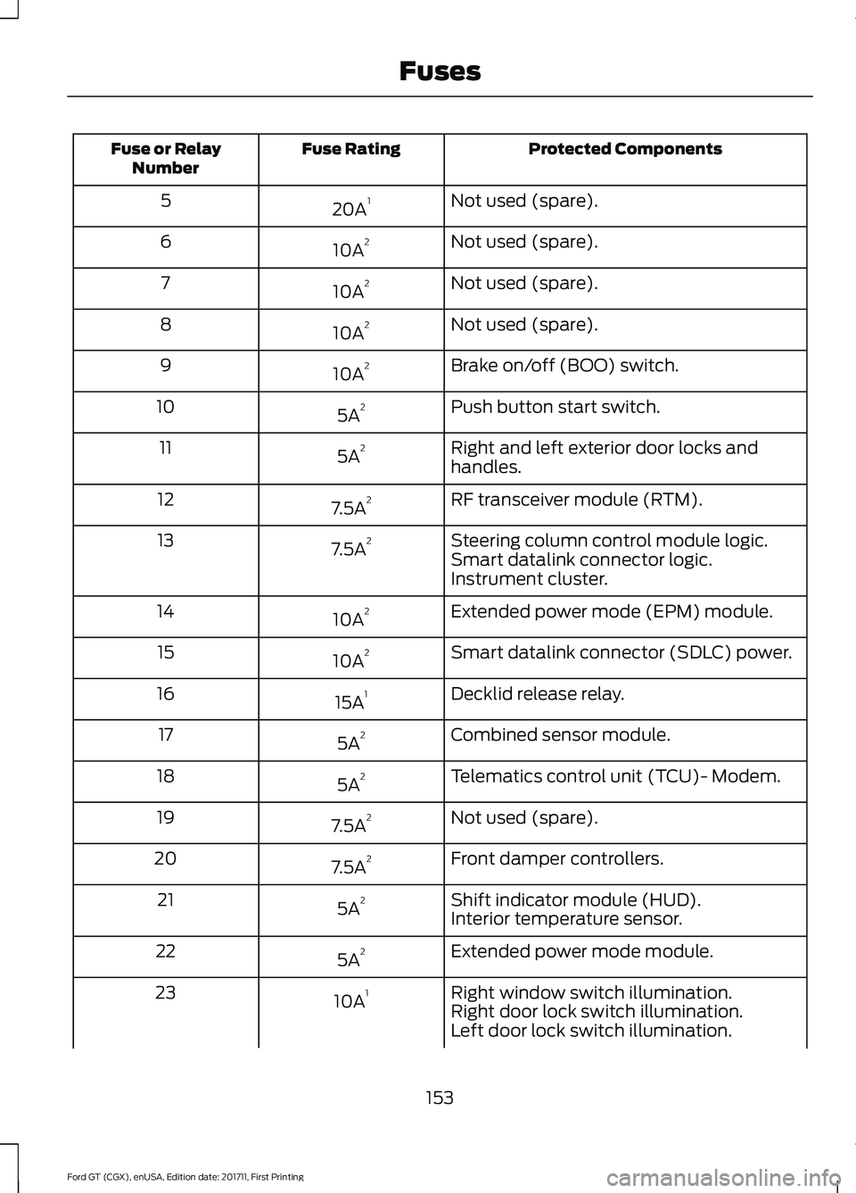
Protected Components
Fuse Rating
Fuse or Relay
Number
Not used (spare).
20A 1
5
Not used (spare).
10A 2
6
Not used (spare).
10A 2
7
Not used (spare).
10A 2
8
Brake on/off (BOO) switch.
10A 2
9
Push button start switch.
5A 2
10
Right and left exterior door locks and
handles.
5A 2
11
RF transceiver module (RTM).
7.5A 2
12
Steering column control module logic.
7.5A 2
13
Smart datalink connector logic.
Instrument cluster.
Extended power mode (EPM) module.
10A 2
14
Smart datalink connector (SDLC) power.
10A 2
15
Decklid release relay.
15A 1
16
Combined sensor module.
5A 2
17
Telematics control unit (TCU)- Modem.
5A 2
18
Not used (spare).
7.5A 2
19
Front damper controllers.
7.5A 2
20
Shift indicator module (HUD).
5A 2
21
Interior temperature sensor.
Extended power mode module.
5A 2
22
Right window switch illumination.
10A 1
23
Right door lock switch illumination.
Left door lock switch illumination.
153
Ford GT (CGX), enUSA, Edition date: 201711, First Printing Fuses
Page 157 of 325
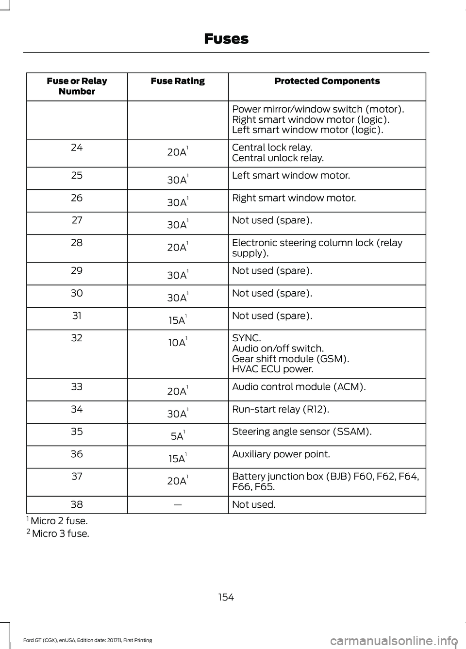
Protected Components
Fuse Rating
Fuse or Relay
Number
Power mirror/window switch (motor).
Right smart window motor (logic).
Left smart window motor (logic).
Central lock relay.
20A 1
24
Central unlock relay.
Left smart window motor.
30A 1
25
Right smart window motor.
30A 1
26
Not used (spare).
30A 1
27
Electronic steering column lock (relay
supply).
20A 1
28
Not used (spare).
30A 1
29
Not used (spare).
30A 1
30
Not used (spare).
15A 1
31
SYNC.
10A 1
32
Audio on/off switch.
Gear shift module (GSM).
HVAC ECU power.
Audio control module (ACM).
20A 1
33
Run-start relay (R12).
30A 1
34
Steering angle sensor (SSAM).
5A 1
35
Auxiliary power point.
15A 1
36
Battery junction box (BJB) F60, F62, F64,
F66, F65.
20A 1
37
Not used.
—
38
1 Micro 2 fuse.
2 Micro 3 fuse.
154
Ford GT (CGX), enUSA, Edition date: 201711, First Printing Fuses
Page 163 of 325
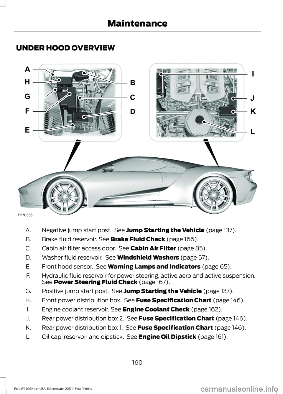
UNDER HOOD OVERVIEW
Negative jump start post. See Jump Starting the Vehicle (page 137).
A.
Brake fluid reservoir.
See Brake Fluid Check (page 166).
B.
Cabin air filter access door. See
Cabin Air Filter (page 85).
C.
Washer fluid reservoir. See
Windshield Washers (page 57).
D.
Front hood sensor. See
Warning Lamps and Indicators (page 65).
E.
Hydraulic fluid reservoir for power steering, active aero and active suspension.
See
Power Steering Fluid Check (page 167).
F.
Positive jump start post. See
Jump Starting the Vehicle (page 137).
G.
Front power distribution box. See
Fuse Specification Chart (page 146).
H.
Engine coolant reservoir.
See Engine Coolant Check (page 162).
I.
Rear power distribution box 2. See
Fuse Specification Chart (page 146).
J.
Rear power distribution box 1. See
Fuse Specification Chart (page 146).
K.
Oil cap, reservoir and dipstick. See
Engine Oil Dipstick (page 161).
L.
160
Ford GT (CGX), enUSA, Edition date: 201711, First Printing MaintenanceE270336
Page 184 of 325
General Information
WARNING
Failure to follow these guidelines
could result in an increased risk of
loss of vehicle control, injury or death.
Note:
Do not use the kit if you have severely
damaged a tire. Only seal punctures located
within the tire tread with the kit.
Do not attempt to repair punctures larger
than ¼ inch (6 millimeters) or damage to
the tire's sidewall. The tire may not
completely seal.
Loss of air pressure may adversely affect
tire performance. For this reason:
Note: Do not drive the vehicle above
50 mph (80 km/h).
Note: Do not drive further than
120 mi
(200 km). Drive only to the closest
authorized Ford dealer or tire repair shop to
have your tire inspected.
• Drive carefully and avoid abrupt
steering maneuvers.
• Periodically monitor tire inflation
pressure in the affected tire; if the tire
is losing pressure, have the vehicle
towed on a flat bed.
• Read the information in the Tips for
Use of the Kit section to make sure safe
operation of the kit and your vehicle.
Tips for Use of the Kit
To ensure safe operation of the kit:
• Read all instructions and cautions fully.
• Before operating the kit, make sure
your vehicle is safely off the road and
away from moving traffic. Switch on
the hazard lights.
• Always set the parking brake to ensure
the vehicle does not move
unexpectedly. •
Do not remove any foreign objects,
such as nails or screws, from the tire.
• When using the kit, leave the engine
running (only if the vehicle is outdoors
or in a well-ventilated area) so the
compressor does not drain the
vehicle's battery.
• Do not allow the compressor to
operate continuously for more than 15
minutes. This will help prevent the
compressor from overheating.
• Never leave the kit unattended during
operation.
• Sealant compound contains latex.
Those with latex sensitivities should
use appropriate precautions to avoid
an allergic reaction.
• Keep the kit away from children.
• Only use the kit when the ambient
temperature is between -22°F (-30°C)
and 158°F (70°C).
• Only use the sealing compound before
the use-by date. The use-by date is on
a label on the sealant canister, which
you can see through the rectangular
viewing window on the bottom of the
compressor. Check the use-by date
regularly and replace the canister after
four years of non-use.
• Do not store the kit unsecured inside
the passenger compartment of the
vehicle as it may cause injury during a
sudden stop or crash. Always store the
kit in its original location.
• After sealant use, an authorized Ford
dealer must replace the tire pressure
monitoring system sensor and valve
stem on the wheel.
• Operating the kit could cause an
electrical disturbance in radio
operation.
181
Ford GT (CGX), enUSA, Edition date: 201711, First Printing Wheels and Tires
Page 199 of 325
WARNINGS
labels, then you should contact
your authorized dealer as soon as
possible. Use of any tire or wheel
not recommended by Ford can
affect the safety and performance
of your vehicle, which could result
in an increased risk of loss of
vehicle control, vehicle rollover,
personal injury and death. The use of
non-recommended tires and
wheels could cause steering,
suspension, axle, transfer case or
power transfer unit failure. If you
have questions regarding tire
replacement, contact your
authorized dealer as soon as
possible. To reduce the risk of serious
injury, when mounting
replacement tires and wheels, you
should not exceed the maximum
pressure indicated on the sidewall
of the tire to set the beads without
additional precautions listed
below. If the beads do not seat at
the maximum pressure indicated,
re-lubricate and try again. When inflating the tire for
mounting pressures up to
20 psi (1.38 bar) greater than the
maximum pressure on the tire
sidewall, the following
precautions must be taken to
protect the person mounting the
tire: •
Make sure that you have the
correct tire and wheel size.
• Lubricate the tire bead and
wheel bead seat area again.
• Stand at a minimum of
12 ft
(3.66 m) away from the wheel
and tire assembly.
• Use both eye and ear
protection. WARNINGS
For a mounting pressure
more than
20 psi (1.38 bar)
greater than the maximum
pressure, a Ford dealer or other
tire service professional should do
the mounting. Always inflate steel carcass
tires with a remote air fill with
the person inflating standing at a
minimum of
12 ft (3.66 m) away
from the wheel and tire assembly. Important: Remember to replace
the wheel valve stems when the
road tires are replaced on your
vehicle.
It is recommended that the two
front tires or two rear tires
generally be replaced as a pair.
The tire pressure sensors mounted
in the wheels (originally installed
on your vehicle) are not designed
to be used in aftermarket wheels.
196
Ford GT (CGX), enUSA, Edition date: 201711, First Printing Wheels and Tires
Page 202 of 325
WARNINGS
If the tire pressure monitor sensor
becomes damaged it may not
function.
Each tire should be checked
monthly when cold and inflated
to the inflation pressure
recommended by the vehicle manufacturer
on the vehicle placard or tire inflation
pressure label. (If your vehicle has tires of
a different size than the size indicated on
the vehicle placard or tire inflation pressure
label, you should determine the proper tire
inflation pressure for those tires.)
As an added safety feature, your vehicle
has been equipped with a Tire Pressure
Monitoring System (TPMS) that
illuminates a low tire pressure telltale
when one or more of your tires is
significantly under-inflated. Accordingly,
when the low tire pressure telltale
illuminates, you should stop and check
your tires as soon as possible, and inflate
them to the proper pressure. Driving on a
significantly under-inflated tire causes the
tire to overheat and can lead to tire failure.
Under-inflation also reduces fuel efficiency
and tire tread life, and may affect the
vehicle ’s handling and stopping ability.
Please note that the TPMS is not a
substitute for proper tire maintenance, and
it is the driver ’s responsibility to maintain
correct tire pressure, even if under-inflation
has not reached the level to trigger
illumination of the TPMS low tire pressure
telltale. Your vehicle has also been equipped with
a TPMS malfunction indicator to indicate
when the system is not operating properly.
The TPMS malfunction indicator is
combined with the low tire pressure
telltale. When the system detects a
malfunction, the telltale flashes for
approximately one minute and then
remains illuminated. This sequence
continues upon subsequent vehicle
start-ups as long as the malfunction exists.
When the malfunction indicator is
illuminated, the system may not be able
to detect or signal low tire pressure as
intended. TPMS malfunctions may occur
for a variety of reasons, including the
installation of replacement or alternate
tires or wheels on the vehicle that prevent
the TPMS from functioning properly.
Always check the TPMS malfunction
telltale after replacing one or more tires or
wheels on your vehicle to ensure that the
replacement or alternate tires and wheels
allow the TPMS to continue to function
properly.
This device complies with Part 15 of the
FCC Rules and with Licence exempt RSS
Standards of Industry Canada. Operation
is subject to the following two conditions:
•
This device may not cause harmful
interference, and
• This device must accept any
interference received, including
interference that may cause undesired
operation. WARNING
Changes or modifications not
expressively approved by the party
responsible for compliance could
void the user's authority to operate the
equipment. The term "IC:" before the radio
certification number only signifies that
Industry Canada technical specifications
were met. 199
Ford GT (CGX), enUSA, Edition date: 201711, First Printing Wheels and Tires
Page 203 of 325
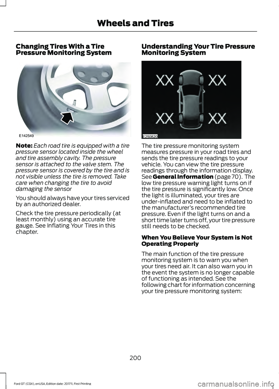
Changing Tires With a Tire
Pressure Monitoring System
Note:
Each road tire is equipped with a tire
pressure sensor located inside the wheel
and tire assembly cavity. The pressure
sensor is attached to the valve stem. The
pressure sensor is covered by the tire and is
not visible unless the tire is removed. Take
care when changing the tire to avoid
damaging the sensor
You should always have your tires serviced
by an authorized dealer.
Check the tire pressure periodically (at
least monthly) using an accurate tire
gauge. See Inflating Your Tires in this
chapter. Understanding Your Tire Pressure
Monitoring System The tire pressure monitoring system
measures pressure in your road tires and
sends the tire pressure readings to your
vehicle. You can view the tire pressure
readings through the information display.
See General Information (page 70). The
low tire pressure warning light turns on if
the tire pressure is significantly low. Once
the light is illuminated, your tires are
under-inflated and need to be inflated to
the manufacturer ’s recommended tire
pressure. Even if the light turns on and a
short time later turns off, your tire pressure
still needs to be checked.
When You Believe Your System is Not
Operating Properly
The main function of the tire pressure
monitoring system is to warn you when
your tires need air. It can also warn you in
the event the system is no longer capable
of functioning as intended. See the
following chart for information concerning
your tire pressure monitoring system:
200
Ford GT (CGX), enUSA, Edition date: 201711, First Printing Wheels and TiresE142549 E250820