Anti Lock Brake System FORD KUGA 2011 1.G User Guide
[x] Cancel search | Manufacturer: FORD, Model Year: 2011, Model line: KUGA, Model: FORD KUGA 2011 1.GPages: 2057
Page 376 of 2057
Daytime Running Lamps (DRL)
Refer to Wiring Diagrams Section 417-04, for
schematic and connector information.
Special Tool(s)
Terminal Probe Kit
29-011ADescription of operation
A diagnosis of the generic electronic module (GEM)
can be performed with the Ford approved
diagnostic tool. Furthermore, an integrated service
mode enables testing of the input and output
signals without the need for further tools. To enable
activation of service mode:
• switch off the ignition,
• switch off all other electrical consumers,
• apply the handbrake,
• shift to neutral
• and close the doors.
Activating the service mode
Proceed as follows to activate the service mode:
•
OPERATE the switch of the heated rear window
and HOLD IT THERE
• Turn on the ignition.
• RELEASE the switch of the heated rear window
A signal sounds and the turn signal lamps come
on to indicate that service mode has been
successfully activated.
NOTE: If the alarm is activated (in vehicles fitted
with an anti-theft alarm system), service mode
cannot be activated.
Inputs
SWITCH the windshield wiper switch to the "Off"
position to test the input signals. The following is
a list of the switch signals to be tested, in no
particular order:
• Turn signals (right, left, hazard warning lights)
• Windshield wiper stage I
• Windshield wiper stage II
• Windshield washer system • Rear window wiper
• Rear window washer system
• Doors open/closed
• Remote control for central locking with double
locking
• Hood open/closed (in vehicles equipped with an anti-theft alarm system)
• Tailgate open/closed
• A/C request signal
• Heated windscreen (if fitted)
• Parking Brake
• Brake reservoir fluid level
• Speed control system
• Autolamps
• dipped beam
• main beam
• headlamp flasher
• Marker Lamps
• Reversing lamp
• Liftgate release
• Ignition switch, terminal 15 (turn key to 0 position, then turn key to II position.)
An acoustic signal sounds and the turn signal
lamps flash to indicate receipt of each input signal
by the generic electronic module.
Test the windshield wiper "intermittent mode" stage
input signal (only vehicles with adjustable
intermittent mode)
The windshield wiper switch must be switched to
"intermittent mode" in order to test the input signal.
The delay times of the input signals can then be
tested by operating the rotary switch. Each change
of the rotary switch position is indicated by an
acoustic signal and illumination of the turn signals.
Output signals
SWITCH the wiper switch to the "intermittent""
position to test the output signals. PRESSING the
heated rear window switch activates the output
signals in the following order:
a. Turn Indicator Left Hand
b. Turn Indicator Right Hand
c. main beam
d. dipped beam
e. Windshield wiper stage I
f. Windshield wiper stage II G1055032en
2008.50 Kuga 8/2011 417-04-2
Daytime Running Lamps (DRL)
417-04-2
DIAGNOSIS AND TESTINGTO MODEL INDEX
BACK TO CHAPTER INDEX
FORD KUGA 2011.0MY WORKSHOP REPAIR MANUAL29011A
Page 380 of 2057
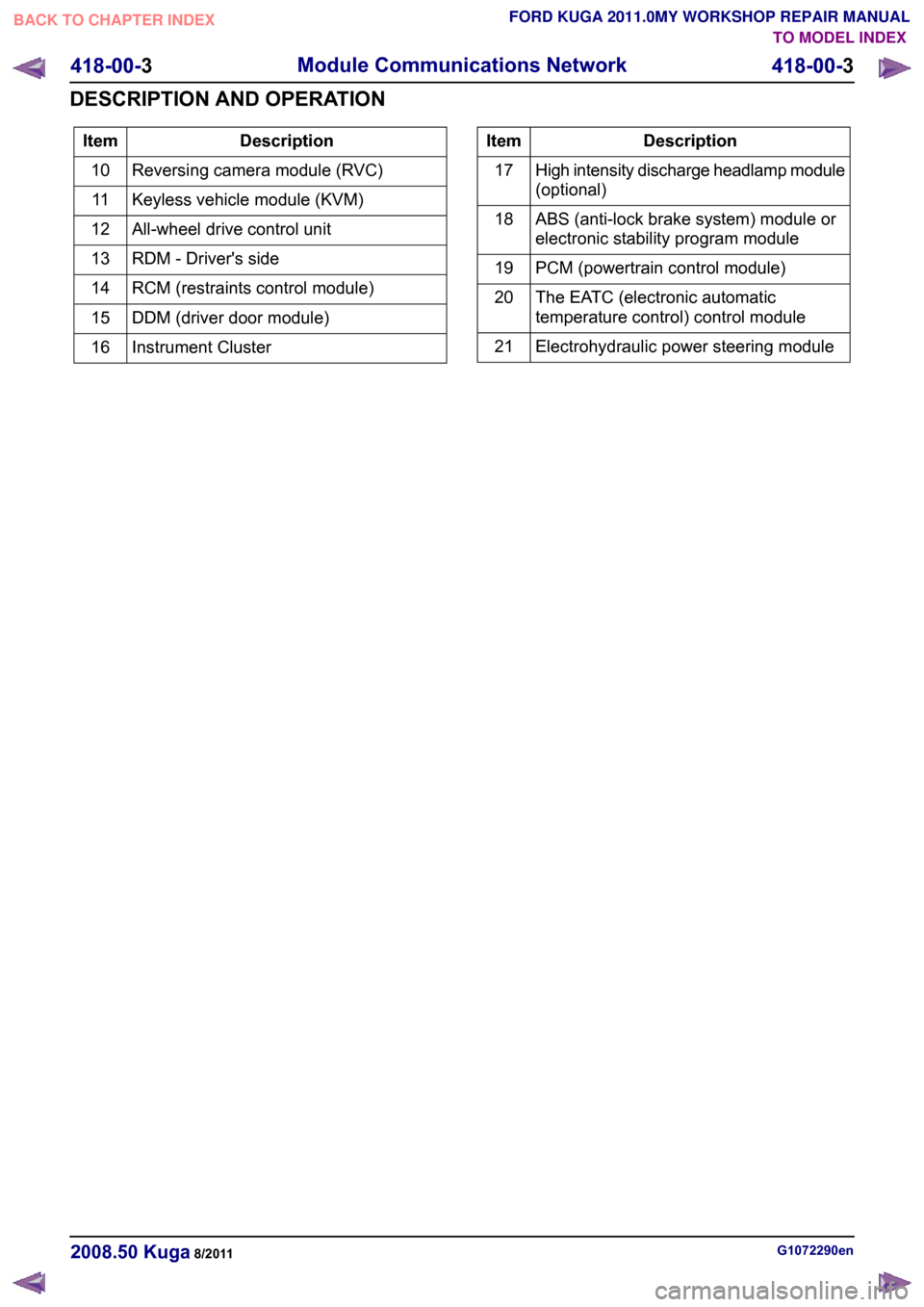
Description
Item
Reversing camera module (RVC)
10
Keyless vehicle module (KVM)
11
All-wheel drive control unit
12
RDM - Driver's side
13
RCM (restraints control module)
14
DDM (driver door module)
15
Instrument Cluster
16 Description
Item
High intensity discharge headlamp module
(optional)
17
ABS (anti-lock brake system) module or
electronic stability program module
18
PCM (powertrain control module)
19
The EATC (electronic automatic
temperature control) control module
20
Electrohydraulic power steering module
21 G1072290en
2008.50 Kuga 8/2011 418-00-3
Module Communications Network
418-00-3
DESCRIPTION AND OPERATIONTO MODEL INDEX
BACK TO CHAPTER INDEX
FORD KUGA 2011.0MY WORKSHOP REPAIR MANUAL
Page 452 of 2057
Module Controlled Functions – Overview
Generic electronics module (GEM)
CAUTIONS:
Never swap the GEM (generic electronic
module) between two vehicles.
Compare the number of relays and fuses
in the defective GEM and the new GEM.
Transfer from the defective GEM any relays
and fuses which are not in the new GEM.
In doing so, pay attention that fuses with
the correct Ampere rating are used, by
referring to the wiring diagrams.
NOTE: The GEM is integrated in the CJB (central
junction box) and cannot be replaced as a separate
unit.
For repair work during a service, vehicle-specific
configuration is necessary if a new GEM is
installed.
Emergency function
The GEM is equipped with restricted emergency
running functions on vehicles with mid or high-end
equipment levels.
The microcontroller sends a control signal to a
monitoring function within the GEM at regular
intervals. If the battery voltage falls below a value
of approx. 7.5 volts, this check signal is not present
and the GEM switches to emergency function after
a predetermined time.
In this case, the low beam is permanently switched
on, regardless of the light switch position. The
windshield wiper can only be operated in stage 1;
the wiper switch must however be in the stage I or
II position. The wiper park position is not
recognized. Intermittent wiping is not available.
When the control signal recurs, the GEM switches
back to normal operation.
Service mode
Description of operation
Diagnosis of the GEM can be carried out using the
Ford diagnostic unit. Furthermore, an integrated
service mode enables testing of the input and
output signals without the need for further tools.
To enable activation of service mode: • switch off the ignition,
• switch off all other electrical consumers,
• apply the handbrake,
• Shift to neutral
• and close the doors.
Activating the service mode
NOTE:
If the alarm is activated (in vehicles fitted
with an anti-theft alarm system), service mode
cannot be activated.
Proceed as follows to activate the service mode:
• OPERATE the switch of the heated rear window
and HOLD IT THERE
• SWITCH ON the ignition.
• RELEASE the switch of the heated rear window
A signal sounds and the turn signal lamps come
on to indicate that service mode has been
successfully activated.
Inputs
SWITCH the windshield wiper switch to the "OFF"
position to test the input signals. The following is
a list of the switch signals to be tested, in no
particular order:
• Windshield wiper stage I
• Windshield wiper stage II
• Windshield washer system
• Rear window wiper
• Rear window washer system
• Doors open/closed
• Remote control for central locking with double locking
• Hood open/closed (in vehicles equipped with an anti-theft alarm system)
• Tailgate open/closed
• A/C request signal
• Heated windscreen (if fitted)
• Parking brake
• Brake fluid level
• Cruise control system
• Autolamps
• Dipped beam
• Main beam
• Headlamp flasher
• Side lights
• Turn signals (right, left, hazard warning lights) G1030787en
2008.50 Kuga 8/2011 419-10-2
Multifunction Electronic Modules
419-10-2
DESCRIPTION AND OPERATIONTO MODEL INDEX
BACK TO CHAPTER INDEX
FORD KUGA 2011.0MY WORKSHOP REPAIR MANUAL
Page 456 of 2057
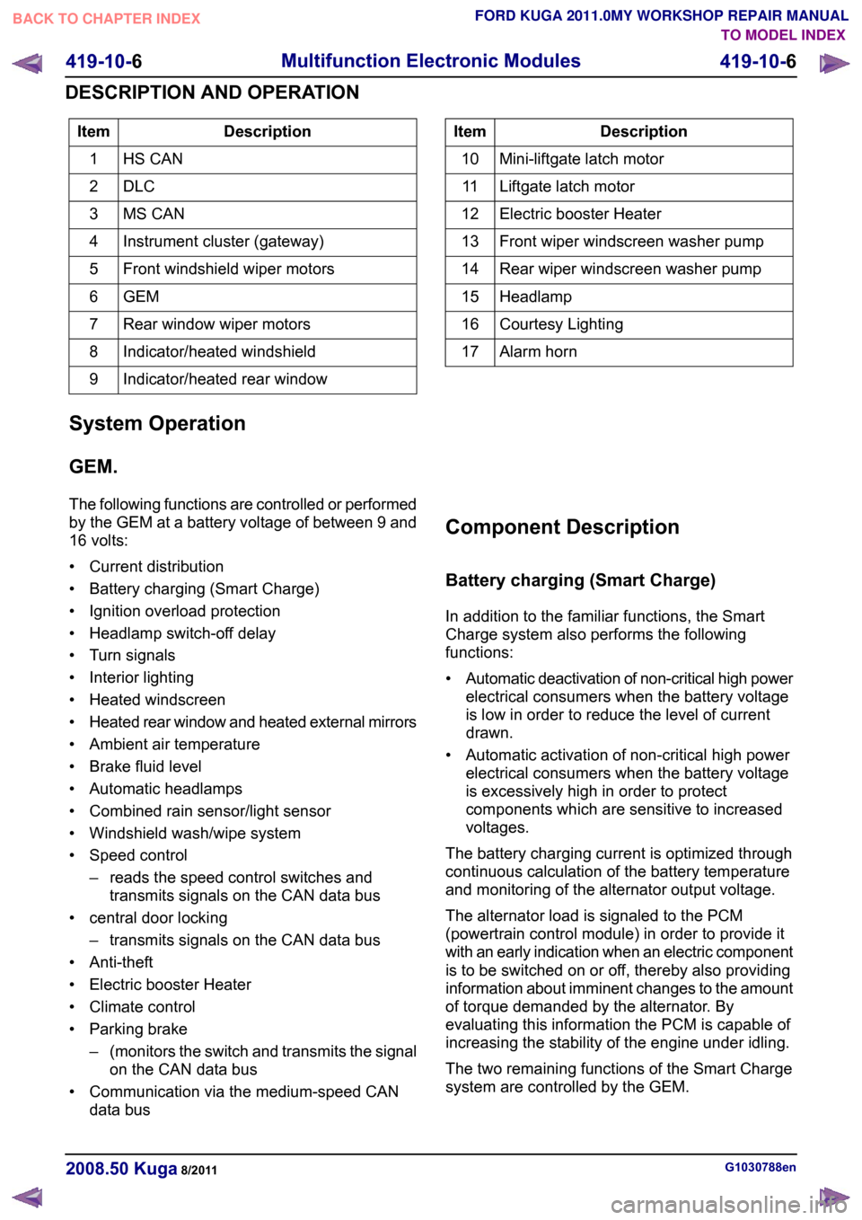
Description
Item
HS CAN
1
DLC2
MS CAN
3
Instrument cluster (gateway)
4
Front windshield wiper motors
5
GEM6
Rear window wiper motors
7
Indicator/heated windshield
8
Indicator/heated rear window
9 Description
Item
Mini-liftgate latch motor
10
Liftgate latch motor
11
Electric booster Heater
12
Front wiper windscreen washer pump
13
Rear wiper windscreen washer pump
14
Headlamp
15
Courtesy Lighting
16
Alarm horn
17
System Operation
GEM.
The following functions are controlled or performed
by the GEM at a battery voltage of between 9 and
16 volts:
• Current distribution
• Battery charging (Smart Charge)
• Ignition overload protection
• Headlamp switch-off delay
• Turn signals
• Interior lighting
• Heated windscreen
• Heated rear window and heated external mirrors
• Ambient air temperature
• Brake fluid level
• Automatic headlamps
• Combined rain sensor/light sensor
• Windshield wash/wipe system
• Speed control – reads the speed control switches andtransmits signals on the CAN data bus
• central door locking – transmits signals on the CAN data bus
• Anti-theft
• Electric booster Heater
• Climate control
• Parking brake –(monitors the switch and transmits the signal
on the CAN data bus
• Communication via the medium-speed CAN data bus Component Description
Battery charging (Smart Charge)
In addition to the familiar functions, the Smart
Charge system also performs the following
functions:
•
Automatic deactivation of non-critical high power
electrical consumers when the battery voltage
is low in order to reduce the level of current
drawn.
• Automatic activation of non-critical high power electrical consumers when the battery voltage
is excessively high in order to protect
components which are sensitive to increased
voltages.
The battery charging current is optimized through
continuous calculation of the battery temperature
and monitoring of the alternator output voltage.
The alternator load is signaled to the PCM
(powertrain control module) in order to provide it
with an early indication when an electric component
is to be switched on or off, thereby also providing
information about imminent changes to the amount
of torque demanded by the alternator. By
evaluating this information the PCM is capable of
increasing the stability of the engine under idling.
The two remaining functions of the Smart Charge
system are controlled by the GEM. G1030788en
2008.50 Kuga 8/2011 419-10-6
Multifunction Electronic Modules
419-10-6
DESCRIPTION AND OPERATIONTO MODEL INDEX
BACK TO CHAPTER INDEX
FORD KUGA 2011.0MY WORKSHOP REPAIR MANUAL
Page 461 of 2057
Generic Electronic Module (GEM)
Refer to Wiring Diagrams Section 419-10, for
schematic and connector information.
Special Tool(s) / General Equipment
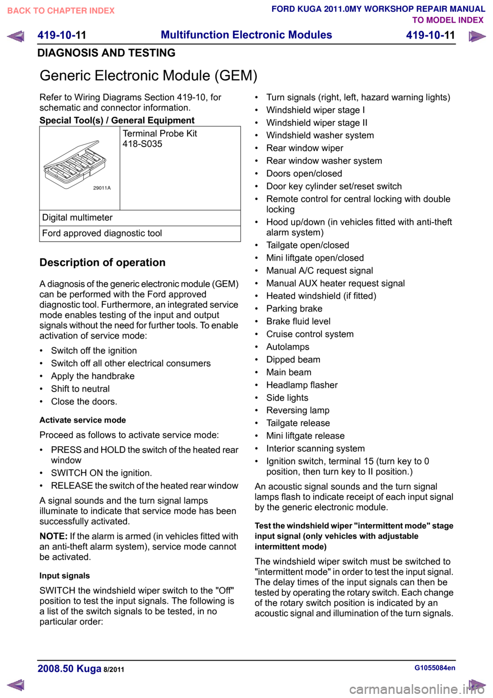
Terminal Probe Kit
418-S035Digital multimeter
Ford approved diagnostic tool
Description of operation
A diagnosis of the generic electronic module (GEM)
can be performed with the Ford approved
diagnostic tool. Furthermore, an integrated service
mode enables testing of the input and output
signals without the need for further tools. To enable
activation of service mode:
• Switch off the ignition
• Switch off all other electrical consumers
• Apply the handbrake
• Shift to neutral
• Close the doors.
Activate service mode
Proceed as follows to activate service mode:
• PRESS and HOLD the switch of the heated rear
window
• SWITCH ON the ignition.
• RELEASE the switch of the heated rear window
A signal sounds and the turn signal lamps
illuminate to indicate that service mode has been
successfully activated.
NOTE: If the alarm is armed (in vehicles fitted with
an anti-theft alarm system), service mode cannot
be activated.
Input signals
SWITCH the windshield wiper switch to the "Off"
position to test the input signals. The following is
a list of the switch signals to be tested, in no
particular order: • Turn signals (right, left, hazard warning lights)
• Windshield wiper stage I
• Windshield wiper stage II
• Windshield washer system
• Rear window wiper
• Rear window washer system
• Doors open/closed
• Door key cylinder set/reset switch
• Remote control for central locking with double
locking
• Hood up/down (in vehicles fitted with anti-theft alarm system)
• Tailgate open/closed
• Mini liftgate open/closed
• Manual A/C request signal
• Manual AUX heater request signal
• Heated windshield (if fitted)
• Parking brake
• Brake fluid level
• Cruise control system
• Autolamps
• Dipped beam
• Main beam
• Headlamp flasher
• Side lights
• Reversing lamp
• Tailgate release
• Mini liftgate release
• Interior scanning system
• Ignition switch, terminal 15 (turn key to 0 position, then turn key to II position.)
An acoustic signal sounds and the turn signal
lamps flash to indicate receipt of each input signal
by the generic electronic module.
Test the windshield wiper "intermittent mode" stage
input signal (only vehicles with adjustable
intermittent mode)
The windshield wiper switch must be switched to
"intermittent mode" in order to test the input signal.
The delay times of the input signals can then be
tested by operating the rotary switch. Each change
of the rotary switch position is indicated by an
acoustic signal and illumination of the turn signals. G1055084en
2008.50 Kuga 8/2011 419-10-11
Multifunction Electronic Modules
419-10-11
DIAGNOSIS AND TESTINGTO MODEL INDEX
BACK TO CHAPTER INDEX
FORD KUGA 2011.0MY WORKSHOP REPAIR MANUAL29011A
Page 1234 of 2057
Engine Speed Sensitive
This means that the vibration occurs at varying
vehicle speeds when a different transmission gear
is selected. It can sometimes be isolated by
increasing or decreasing engine speed with the
transmission in NEUTRAL or by stall testing with
the transmission in gear. If the condition is engine
speed sensitive, the cause is probably not related
to the tires.
If the road test indicates that there is tire whine,
but no shake or vibration, the noise originates with
the contact between the tire and the road surface.A thumping noise usually means that the tire is flat
or has soft spots making a noise as they slap the
roadway. Tire whine can be distinguished from axle
noise. Tire whine remains the same over a range
of speeds.
A complete road test procedure is described in
Section 100-04.
REFER to:
Noise, Vibration and Harshness (NVH)
(100-04 Noise, Vibration and Harshness,
Diagnosis and Testing).
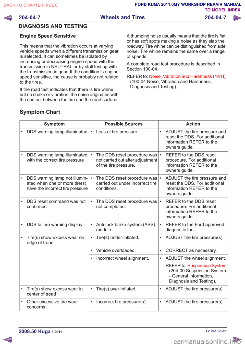
Symptom Chart
Action
Possible Sources
Symptom
• ADJUST the tire pressure andreset the DDS. For additional
information REFER to the
owners guide.
• Loss of tire pressure.
• DDS warning lamp illuminated
• REFER to the DDS resetprocedure. For additional
information REFER to the
owners guide.
• The DDS reset procedure was
not carried out after adjustment
of the tire pressure.
• DDS warning lamp illuminated
with the correct tire pressure
• ADJUST the tire pressure andreset the DDS. For additional
information REFER to the
owners guide.
• The DDS reset procedure was
carried out under incorrect tire
conditions.
• DDS warning lamp not illumin-
ated when one or more tire(s)
have the incorrect tire pressure
• REFER to the DDS resetprocedure. For additional
information REFER to the
owners guide.
• The DDS reset procedure was
not completed.
• DDS reset command was not
confirmed
• REFER to the Ford approveddiagnostic tool.
• Anti-lock brake system (ABS)
module.
• DDS failure warning display
• ADJUST the tire pressure(s).
• Tire(s) under-inflated.
• Tire(s) show excess wear on
edge of tread
• CORRECT as necessary.
• Vehicle overloaded.
• ADJUST the wheel alignment.REFER to: Suspension System
(204-00 Suspension System
- General Information,
Diagnosis and Testing).
• Incorrect wheel alignment.
• ADJUST the tire pressure(s).
• Tire(s) over-inflated.
• Tire(s) show excess wear in
center of tread
• ADJUST the tire pressure(s).
• Incorrect tire pressure(s).
• Other excessive tire wear
concerns
G1061329en2008.50 Kuga8/2011
204-04- 7
Wheels and Tires
204-04- 7
DIAGNOSIS AND TESTING
TO MODEL INDEX
BACK TO CHAPTER INDEX
FORD KUGA 2011.0MY WORKSHOP REPAIR MANUAL
Page 1342 of 2057
Action
Possible Sources
Symptom
• INSTALL a new brake mastercylinder.
REFER to: Brake Master
Cylinder - 2.5L Duratec
(147kW/200PS) - VI5 (206-06
Hydraulic Brake Actuation,
Removal and Installation).
• Leaking brake master cylinder
primary piston cup.
• FREE UP and ADJUST theparking brake cable.
REFER to: Parking Brake
Cable Adjustment (206-05
Parking Brake and Actuation,
General Procedures).
INSTALL new components as
necessary.
• Parking brake control not fully
released.
• REFER to:Anti-Lock Control
(206-09 Anti-Lock Control,
Diagnosis and Testing).
• Malfunctioning anti-lock braking
system (ABS).
• REFER to:Instrument Cluster
(413-01 Instrument Cluster,
Diagnosis and Testing).
• Shorted indicator circuit.
• INSTALL new brake shoes orbrake pads.
REFER to: Brake Pads (206-03
Front Disc Brake, Removal
and Installation).
• Grease or fluid on the brake
shoes or brake pads; glazed
linings.
• Vibration when the brakes are
applied
• INSTALL new brake shoes orbrake pads.
REFER to: Brake Pads (206-03
Front Disc Brake, Removal
and Installation).
• Worn or damaged brake shoes
or brake pads.
• TIGHTEN the caliper mountingbolt(s).
• Loose caliper mounting bolt(s).
•
• Excessive brake disc thickness
variation or brake disc runout.
• CHECK the tires. BALANCE orINSTALL new tires as neces-
sary.
REFER to: Wheels and Tires
(204-04 Wheels and Tires,
Diagnosis and Testing).
• Wheels and tires.
• TIGHTEN or INSTALL newwheel hub bolts as necessary.
• Loose or missing wheel hub
bolts.
• CARRY OUT a brake discrunout check.
• Worn or damaged brake drums
or brake discs.
G1058975en2008.50 Kuga8/2011
206-00- 6
Brake System - General Information
206-00- 6
DIAGNOSIS AND TESTING
TO MODEL INDEX
BACK TO CHAPTER INDEX
FORD KUGA 2011.0MY WORKSHOP REPAIR MANUAL
Page 1414 of 2057
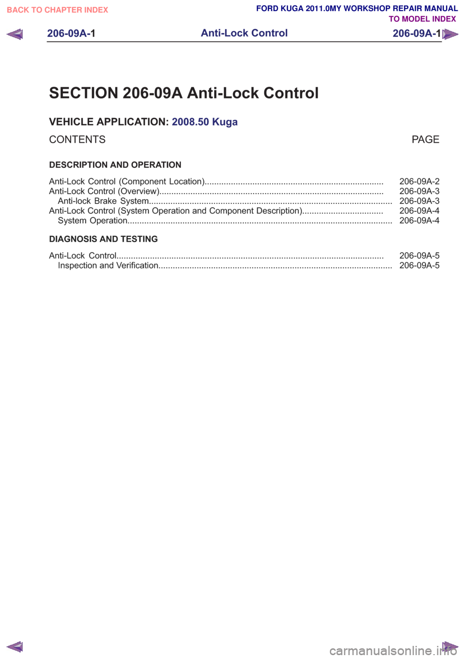
SECTION 206-09A Anti-Lock Control
VEHICLE APPLICATION:2008.50 Kuga
PA G E
CONTENTS
DESCRIPTION AND OPERATION
206-09A-2
Anti-Lock Control (Component Location) ........................................................................\
...
206-09A-3
Anti-Lock Control (Overview) ........................................................................\
......................
206-09A-3
Anti-lock Brake System ........................................................................\
..............................
206-09A-4
Anti-Lock Control (System Operation and Component Description) ..................................
206-09A-4
System Operation ........................................................................\
.......................................
DIAGNOSIS AND TESTING 206-09A-5
Anti-Lock Control ........................................................................\
........................................
206-09A-5
Inspection and Verification ........................................................................\
..........................
206-09A-1
Anti-Lock Control
206-09A- 1
.
TO MODEL INDEX
BACK TO CHAPTER INDEX
FORD KUGA 2011.0MY WORKSHOP REPAIR MANUAL
Page 1415 of 2057
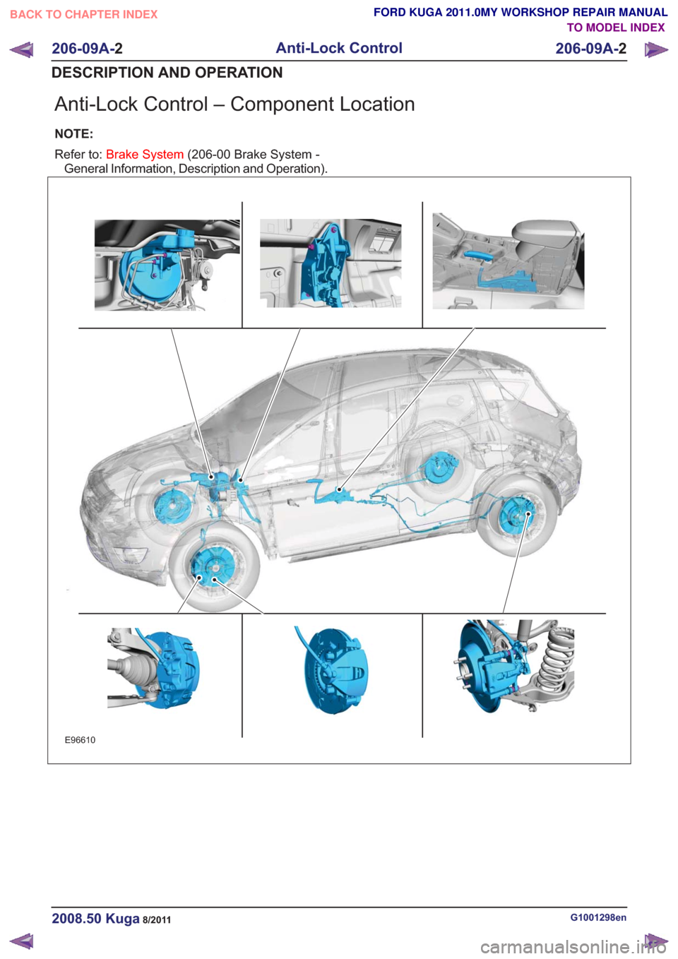
Anti-Lock Control – Component Location
NOTE:
Refer to:Brake System (206-00 Brake System -
General Information, Description and Operation).
E96610
G1001298en2008.50 Kuga8/2011
206-09A- 2
Anti-Lock Control
206-09A- 2
DESCRIPTION AND OPERATION
TO MODEL INDEX
BACK TO CHAPTER INDEX
FORD KUGA 2011.0MY WORKSHOP REPAIR MANUAL
Page 1416 of 2057
Anti-Lock Control – Overview
Anti-lock Brake System
Refer to:Anti-Lock Control - Stability Assist (206-09
Anti-Lock Control - Stability Assist, Description
and Operation).
G1001218en2008.50 Kuga8/2011
206-09A- 3
Anti-Lock Control
206-09A- 3
DESCRIPTION AND OPERATION
TO MODEL INDEX
BACK TO CHAPTER INDEX
FORD KUGA 2011.0MY WORKSHOP REPAIR MANUAL