Brake cylinder FORD KUGA 2011 1.G User Guide
[x] Cancel search | Manufacturer: FORD, Model Year: 2011, Model line: KUGA, Model: FORD KUGA 2011 1.GPages: 2057
Page 1354 of 2057
4. Remove the vacuum hose from the brakebooster. Manifold vacuum should be available
at the brake booster end of the hose with the
engine at idle speed and the transaxle in the
NEUTRAL position. Make sure that all unused
vacuum outlets are correctly capped, hose
connectors are correctly secured and vacuum
hoses are in good condition. When it is
established that manifold vacuum is available
to the brake booster, connect the vacuum hose
to the brake booster and repeat Step 3. If no
downward movement of the brake pedal is felt,
install a new brake booster.
5. Operate the engine a minimum of 10 seconds at approximately 1200 rpm. Stop the engine and
let the vehicle stand for 10 minutes. Then, apply
the brake pedal with approximately 89 N (20 lb)
force. The pedal feel (brake application) should
be the same as that noted with the engine
operating. If the brake pedal feels hard (no
power assist), install a new vacuum check valve
and then repeat the test. If the brake pedal still
feels hard, install a new brake booster. If the
brake pedal movement feels spongy, bleed the
brake system. REFER to: (206-00 Brake System
- General Information)
Brake System Bleeding (General Procedures),
Brake System Pressure Bleeding (General
Procedures),
Component Bleeding (General Procedures).
Brake Master Cylinder
Usually, the first and strongest indicator of anything
wrong with the braking system is a feeling through
the brake pedal. In diagnosing the condition of the
brake master cylinder, check pedal feel as
evidence of a brake concern. Check for the red
brake warning indicator illumination and the fluid
level in the master cylinder reservoir.
Normal Conditions
The following conditions are considered normal
and are not indications that the brake master
cylinder is in need of service.
– Modern brake systems are not designed to
produce as hard a pedal effort as in the past.
Complaints of light pedal efforts should be compared to pedal efforts of another vehicle, of
the same model and year.
– During normal operation of the brake pedal, the fluid level in the reservoir will rise during brake
pedal application and fall during release. The
net fluid level (i.e., after brake pedal application
and release) will remain unchanged.
– A trace of brake fluid will exists on the brake booster shell below the master cylinder
mounting flange. This results from the normal
lubricating action of the master cylinder bore
end seal.
– The fluid level will fall with brake shoe and lining wear.
Abnormal Conditions
NOTE: Prior to performing any diagnosis, make
sure the brake system warning indicator is
functional.
Changes in brake pedal feel or travel are indicators
that something could be wrong with the braking
system. The diagnostic procedure and techniques
use brake pedal feel, warning indicator illumination
and low brake fluid level as indicators in diagnosing
braking system concerns. The following conditions
are considered abnormal and indicate that the
brake master cylinder is in need of service.
– The brake pedal goes down fast. This could be caused by an external or internal leak.
– The brake pedal eases down slowly. This could be caused by an external or internal leak.
– The brake pedal is low and or feels spongy. This condition may be caused by no fluid in the brake
master cylinder reservoir, reservoir cap vent
holes clogged or air in the hydraulic system.
– The brake pedal effort is excessive. This may be caused by a bind or obstruction in the pedal
or linkage, clogged fluid control valve or
insufficient booster vacuum.
– The rear brakes lock up during light pedal force. This may be caused by incorrect tire pressures,
grease or fluid on the brake shoes and linings,
damaged brake shoes and linings, incorrectly
adjusted parking brake, or damaged or
contaminated brake pressure control valves.
– The brake pedal effort is erratic. This condition could be caused by a brake booster malfunction,
extreme caliper piston knock back or incorrectly
installed brake shoes and linings.
– The red brake warning indicator is ON. This may be caused by low fluid level, ignition wire routing
G1058975en2008.50 Kuga8/2011
206-00- 18
Brake System - General Information
206-00- 18
DIAGNOSIS AND TESTING
TO MODEL INDEX
BACK TO CHAPTER INDEX
FORD KUGA 2011.0MY WORKSHOP REPAIR MANUAL
Page 1355 of 2057
too close to the fluid level indicator assembly,
or float assembly damage.
Bypass Condition Test
1. Check the fluid in the brake master cylinderreservoir. Fill the brake master cylinder reservoir
if low or empty.
2. Observe the fluid level in the brake master cylinder reservoir. If after several brake
applications, the fluid level remains the same,
measure the wheel turning torque required to
rotate the wheels with the brakes applied as
follows:
Place the transaxle in the NEUTRAL position.
Raise and support the vehicle. REFER to: (100-02
Jacking and Lifting) Jacking (Description and Operation),
Lifting (Description and Operation).
Apply the brakes with a minimum of 445 N (100
lb) and hold for approximately 15 seconds. With
the brakes still applied, exert a torque on the front
wheels of 10.1 Nm (75 lb ft). If either wheel rotates,
install a new brake master cylinder.
REFER to: Brake Master Cylinder - 2.5L Duratec
(147kW/200PS) - VI5 (206-06 Hydraulic Brake
Actuation, Removal and Installation).
Non-Pressure Leaks
Any empty brake master cylinder reservoir
condition may be caused by two types of
non-pressure external leaks.
Type 1: An external leak may occur at the brake
master cylinder reservoir cap because of incorrect
positioning of the gasket and cap. Reposition the
cap and gasket.
Type 2: An external leak may occur at the brake
master cylinder reservoir mounting seals. Service
such a leak by installing new seals.
G1058975en2008.50 Kuga8/2011
206-00- 19
Brake System - General Information
206-00- 19
DIAGNOSIS AND TESTING
TO MODEL INDEX
BACK TO CHAPTER INDEX
FORD KUGA 2011.0MY WORKSHOP REPAIR MANUAL
Page 1398 of 2057
SECTION 206-06 Hydraulic Brake Actuation
VEHICLE APPLICATION:2008.50 Kuga
PA G E
CONTENTS
REMOVAL AND INSTALLATION
206-06-2
Brake Pedal and Bracket — RHD 4WD/RHD FWD ...........................................................
206-06-5
(12 343 0)
Brake Master Cylinder — 2.5L Duratec (147kW/200PS) - VI5 .......................
206-06-1
Hydraulic Brake Actuation
206-06- 1
.
BACK TO CHAPTER INDEXFORD KUGA 2011.0MY WORKSHOP REPAIR MANUAL
TO MODEL INDEX
Page 1402 of 2057
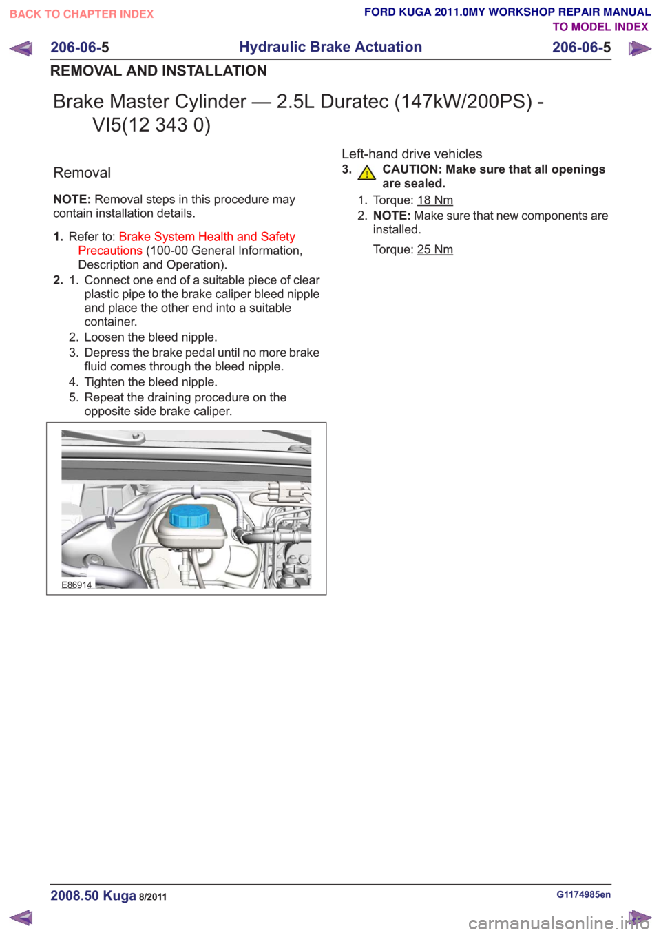
Brake Master Cylinder — 2.5L Duratec (147kW/200PS) -VI5(12 343 0)
Removal
NOTE: Removal steps in this procedure may
contain installation details.
1. Refer to: Brake System Health and Safety
Precautions (100-00 General Information,
Description and Operation).
2. Connect one end of a suitable piece of clear
plastic pipe to the brake caliper bleed nipple
1.
and place the other end into a suitable
container.
2. Loosen the bleed nipple.
3. Depress the brake pedal until no more brake fluid comes through the bleed nipple.
4. Tighten the bleed nipple.
5. Repeat the draining procedure on the opposite side brake caliper.
E86914
Left-hand drive vehicles
3. CAUTION: Make sure that all openings are sealed.
1. Torque: 18Nm
2.NOTE: Make sure that new components are
installed.
Torque: 25
Nm
G1174985en2008.50 Kuga8/2011
206-06- 5
Hydraulic Brake Actuation
206-06- 5
REMOVAL AND INSTALLATION
TO MODEL INDEX
BACK TO CHAPTER INDEX
FORD KUGA 2011.0MY WORKSHOP REPAIR MANUAL
Page 1406 of 2057
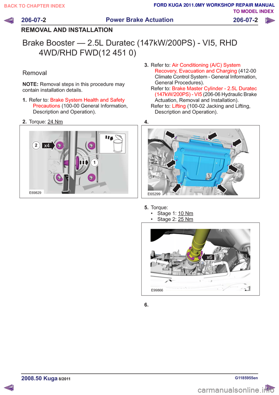
Brake Booster — 2.5L Duratec (147kW/200PS) - VI5, RHD4WD/RHD FWD(12 451 0)
Removal
NOTE: Removal steps in this procedure may
contain installation details.
1. Refer to: Brake System Health and Safety
Precautions (100-00 General Information,
Description and Operation).
2. Torque: 24
Nm
E69829
x4
1
2
3.Refer to: Air Conditioning (A/C) System
Recovery, Evacuation and Charging (412-00
Climate Control System - General Information,
General Procedures).
Refer to: Brake Master Cylinder - 2.5L Duratec
(147kW/200PS) - VI5 (206-06 Hydraulic Brake
Actuation, Removal and Installation).
Refer to: Lifting(100-02 Jacking and Lifting,
Description and Operation).
4.
E65299
5. Torque:
• Stage 1: 10
Nm
• Stage 2: 25Nm
E99866
x6
6.
G1185955en2008.50 Kuga8/2011
206-07- 2
Power Brake Actuation
206-07- 2
REMOVAL AND INSTALLATION
TO MODEL INDEX
BACK TO CHAPTER INDEX
FORD KUGA 2011.0MY WORKSHOP REPAIR MANUAL
Page 1426 of 2057
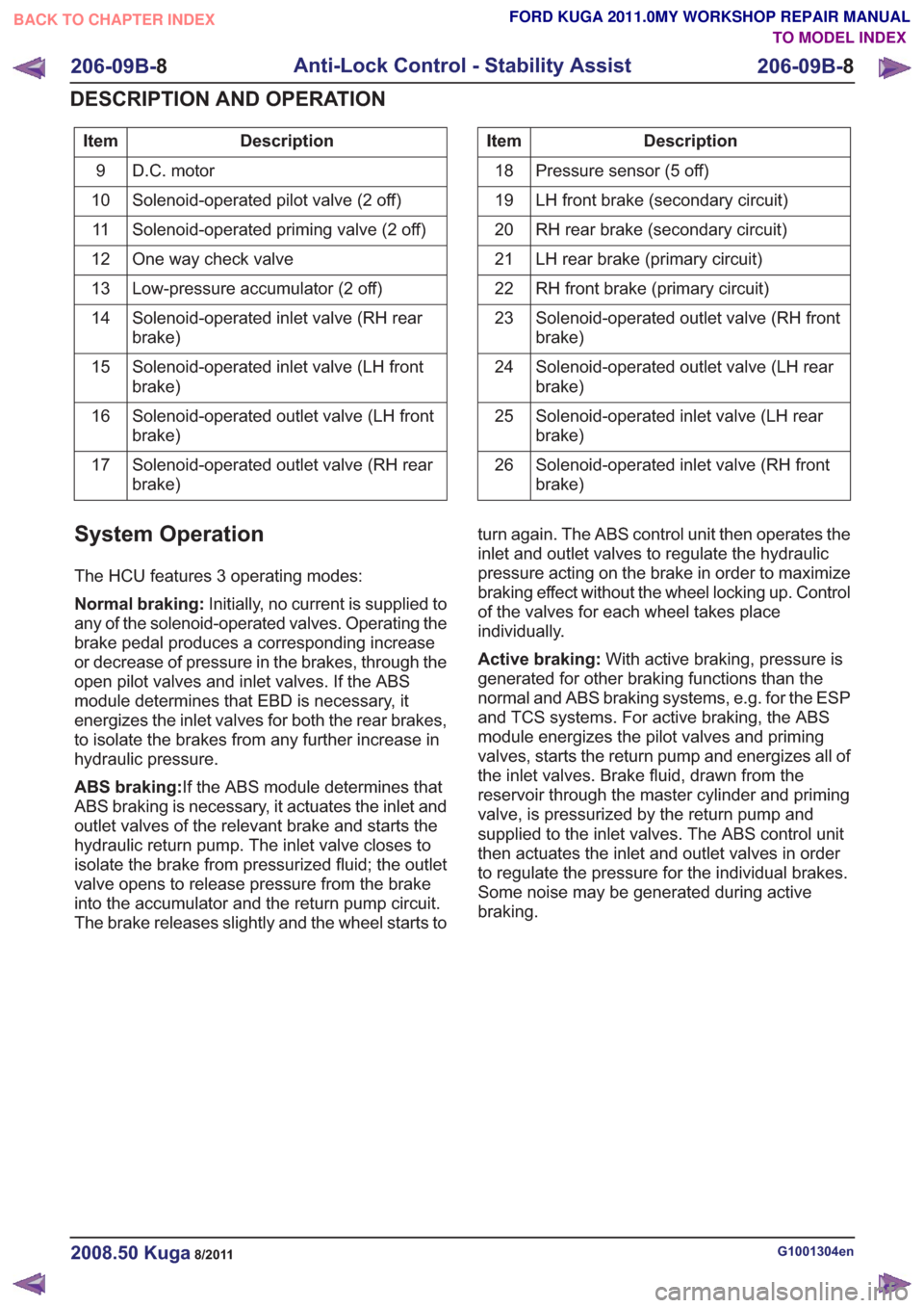
Description
Item
D.C. motor
9
Solenoid-operated pilot valve (2 off)
10
Solenoid-operated priming valve (2 off)
11
One way check valve
12
Low-pressure accumulator (2 off)
13
Solenoid-operated inlet valve (RH rear
brake)
14
Solenoid-operated inlet valve (LH front
brake)
15
Solenoid-operated outlet valve (LH front
brake)
16
Solenoid-operated outlet valve (RH rear
brake)
17Description
Item
Pressure sensor (5 off)
18
LH front brake (secondary circuit)
19
RH rear brake (secondary circuit)
20
LH rear brake (primary circuit)
21
RH front brake (primary circuit)
22
Solenoid-operated outlet valve (RH front
brake)
23
Solenoid-operated outlet valve (LH rear
brake)
24
Solenoid-operated inlet valve (LH rear
brake)
25
Solenoid-operated inlet valve (RH front
brake)
26
System Operation
The HCU features 3 operating modes:
Normal braking:
Initially, no current is supplied to
any of the solenoid-operated valves. Operating the
brake pedal produces a corresponding increase
or decrease of pressure in the brakes, through the
open pilot valves and inlet valves. If the ABS
module determines that EBD is necessary, it
energizes the inlet valves for both the rear brakes,
to isolate the brakes from any further increase in
hydraulic pressure.
ABS braking: If the ABS module determines that
ABS braking is necessary, it actuates the inlet and
outlet valves of the relevant brake and starts the
hydraulic return pump. The inlet valve closes to
isolate the brake from pressurized fluid; the outlet
valve opens to release pressure from the brake
into the accumulator and the return pump circuit.
The brake releases slightly and the wheel starts to turn again. The ABS control unit then operates the
inlet and outlet valves to regulate the hydraulic
pressure acting on the brake in order to maximize
braking effect without the wheel locking up. Control
of the valves for each wheel takes place
individually.
Active braking:
With active braking, pressure is
generated for other braking functions than the
normal and ABS braking systems, e.g. for the ESP
and TCS systems. For active braking, the ABS
module energizes the pilot valves and priming
valves, starts the return pump and energizes all of
the inlet valves. Brake fluid, drawn from the
reservoir through the master cylinder and priming
valve, is pressurized by the return pump and
supplied to the inlet valves. The ABS control unit
then actuates the inlet and outlet valves in order
to regulate the pressure for the individual brakes.
Some noise may be generated during active
braking.
G1001304en2008.50 Kuga8/2011
206-09B- 8
Anti-Lock Control - Stability Assist
206-09B- 8
DESCRIPTION AND OPERATION
TO MODEL INDEX
BACK TO CHAPTER INDEX
FORD KUGA 2011.0MY WORKSHOP REPAIR MANUAL
Page 1710 of 2057
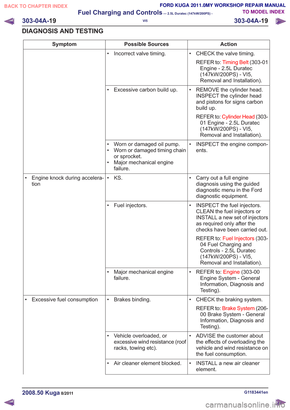
Action
Possible Sources
Symptom
• CHECK the valve timing.REFER to: Timing Belt (303-01
Engine - 2.5L Duratec
(147kW/200PS) - VI5,
Removal and Installation).
• Incorrect valve timing.
• REMOVE the cylinder head.INSPECT the cylinder head
and pistons for signs carbon
build up.
REFER to: Cylinder Head (303-
01 Engine - 2.5L Duratec
(147kW/200PS) - VI5,
Removal and Installation).
• Excessive carbon build up.
• INSPECT the engine compon-ents.
• Worn or damaged oil pump.
• Worn or damaged timing chain
or sprocket.
• Major mechanical engine failure.
• Carry out a full enginediagnosis using the guided
diagnostic menu in the Ford
diagnostic equipment.
• KS.
• Engine knock during accelera-
tion
• INSPECT the fuel injectors.CLEAN the fuel injectors or
INSTALL a new set of injectors
as required only after the
checks have been carried out.
REFER to: Fuel Injectors (303-
04 Fuel Charging and
Controls - 2.5L Duratec
(147kW/200PS) - VI5,
Removal and Installation).
• Fuel injectors.
• REFER to:Engine(303-00
Engine System - General
Information, Diagnosis and
Testing).
• Major mechanical engine
failure.
• CHECK the braking system.REFER to: Brake System (206-
00 Brake System - General
Information, Diagnosis and
Testing).
• Brakes binding.
• Excessive fuel consumption
• ADVISE the customer aboutthe effects of overloading the
vehicle and wind resistance on
the fuel consumption.
• Vehicle overloaded, or
excessive wind resistance (roof
racks, towing etc).
• INSTALL a new air cleanerelement.
• Air cleaner element blocked.
G1183441en2008.50 Kuga8/2011
303-04A-
19
Fuel Charging and Controls
— 2.5L Duratec (147kW/200PS) -
VI5
303-04A- 19
DIAGNOSIS AND TESTING
TO MODEL INDEX
BACK TO CHAPTER INDEX
FORD KUGA 2011.0MY WORKSHOP REPAIR MANUAL
Page 1803 of 2057
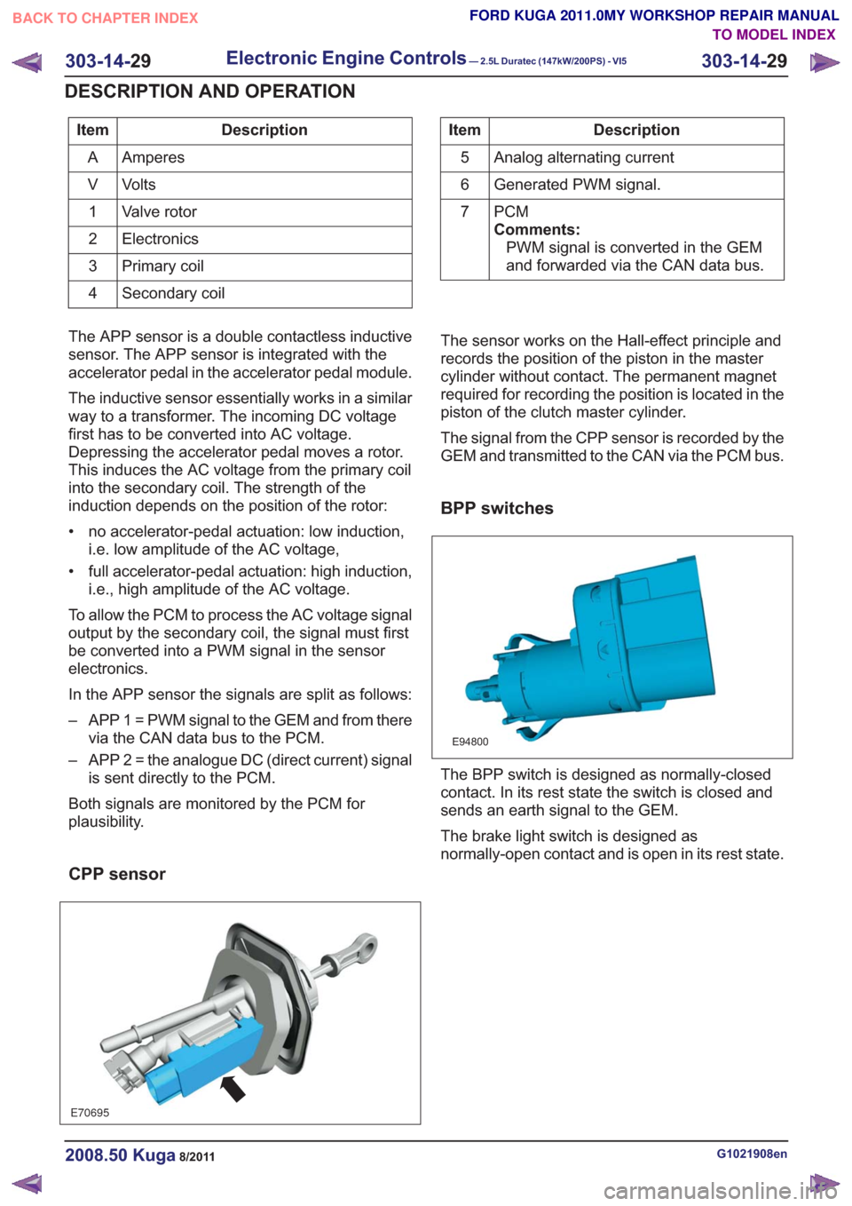
Description
Item
Amperes
A
Volts
V
Valve rotor
1
Electronics
2
Primary coil
3
Secondary coil
4Description
Item
Analog alternating current
5
Generated PWM signal.
6
PCM
Comments:PWM signal is converted in the GEM
and forwarded via the CAN data bus.
7
The APP sensor is a double contactless inductive
sensor. The APP sensor is integrated with the
accelerator pedal in the accelerator pedal module.
The inductive sensor essentially works in a similar
way to a transformer. The incoming DC voltage
first has to be converted into AC voltage.
Depressing the accelerator pedal moves a rotor.
This induces the AC voltage from the primary coil
into the secondary coil. The strength of the
induction depends on the position of the rotor:
• no accelerator-pedal actuation: low induction, i.e. low amplitude of the AC voltage,
• full accelerator-pedal actuation: high induction, i.e., high amplitude of the AC voltage.
To allow the PCM to process the AC voltage signal
output by the secondary coil, the signal must first
be converted into a PWM signal in the sensor
electronics.
In the APP sensor the signals are split as follows:
– APP 1 = PWM signal to the GEM and from there via the CAN data bus to the PCM.
– APP 2 = the analogue DC (direct current) signal is sent directly to the PCM.
Both signals are monitored by the PCM for
plausibility.
CPP sensor
E70695
The sensor works on the Hall-effect principle and
records the position of the piston in the master
cylinder without contact. The permanent magnet
required for recording the position is located in the
piston of the clutch master cylinder.
The signal from the CPP sensor is recorded by the
GEM and transmitted to the CAN via the PCM bus.
BPP switches
E94800
The BPP switch is designed as normally-closed
contact. In its rest state the switch is closed and
sends an earth signal to the GEM.
The brake light switch is designed as
normally-open contact and is open in its rest state.
G1021908en2008.50 Kuga8/2011
303-14- 29
Electronic Engine Controls— 2.5L Duratec (147kW/200PS) - VI5303-14-
29
DESCRIPTION AND OPERATION
TO MODEL INDEX
BACK TO CHAPTER INDEX
FORD KUGA 2011.0MY WORKSHOP REPAIR MANUAL