ignition switch FORD KUGA 2011 1.G User Guide
[x] Cancel search | Manufacturer: FORD, Model Year: 2011, Model line: KUGA, Model: FORD KUGA 2011 1.GPages: 2057
Page 211 of 2057

Description
Item
Rear parking aid sensorRefer to Component Description: Parking
aid sensors (page ?)
7
Rear parking aid sensorRefer to Component Description: Parking
aid sensors (page ?)
8 Description
Item
Rear parking aid sensorRefer to Component Description: Parking
aid sensors (page ?)
9
steering angle sensor
10
Navigation device
11
System Operation
Parking Aid WARNING: It is the driver's responsibility
to stay alert during reversing procedures.
The system may fail to detect small
children or animals.
CAUTION: The driver is responsible for
detecting obstacles and judging the
distance between these and the vehicle.
The system may fail to detect some
hanging objects, barriers, narrow obstacles
or painted surfaces, which could damage
the vehicle. Always pay attention when
parking.
The parking aid provides an audible warning to the
driver if there are any obstacles in front of or behind
the vehicle during reverse parking maneuvers.
At low speeds, the parking aid module uses the
parking aid sensors to monitor the area around the
vehicle. If an object is detected within a monitored
area, the parking aid module emits a warning tone
using the respective parking aid speaker.
The rear parking aid is switched on with the
ignition. However, it is only enabled when reverse
gear is selected.
The front and rear parking aid is always switched
off when the ignition is switched on. It is switched
on when reverse gear is selected or if the parking
aid switch in the center console is actuated up to
a speed of 16 km/h.
The parking aid is switched off when the vehicle is
travelling forwards at more than 16 km/h or if the
parking aid switch in the center console is actuated
again.
When the parking aid module activates the system,
the parking aid switch LED is illuminated. If the
vehicle is only fitted with the rear parking aid, there
is no switch.
The parking aid sensors emit a series of ultrasonic
impulses and switch to receiver mode to receive the echo reflected by an obstacle within the
detection range. The received echo signals are
amplified and converted from an analog signal to
a digital signal by the sensor. The digital signal is
passed to the parking aid module and compared
with pre-programmed data stored in an EEPROM
within the module. The module calculates the
distance to the obstacle by measuring the time
taken between the emitted and received impulses.
If no objects are detected there are no further
warning tones. If an object is detected, repeated
audible tones are emitted from either parking aid
speaker(s) as appropriate. The time delay between
the tones decreases as the distance between the
object and the vehicle decreases, until at
approximately 250 mm (10 inches), the audible
tone becomes continuous.
If the distance between the obstacle and the
vehicle does not decrease, the warning tone
remains constant if the object has been detected
by an internal parking aid sensor. If the obstacle
was detected by an external sensor and the
distance remains unchanged, the warning tone
stops after 3 seconds.
The parking aid module continues to monitor the
distance and will resume the warning tones if a
decrease in distance is detected.
If a trailer is connected to the vehicle, a signal is
sent to the GEM (generic electronic module) via
the trailer relay. This signal is sent to the parking
aid module via the MS CAN bus. When the parking
aid module detects that a trailer is connected to
the vehicle, the rear parking aid sensors are
disabled to prevent constant warnings due to the
close proximity of the trailer.
G1034399en
2008.50 Kuga 8/2011 413-13-12
Parking Aid
413-13-12
DESCRIPTION AND OPERATIONTO MODEL INDEX
BACK TO CHAPTER INDEX
FORD KUGA 2011.0MY WORKSHOP REPAIR MANUAL
Page 214 of 2057
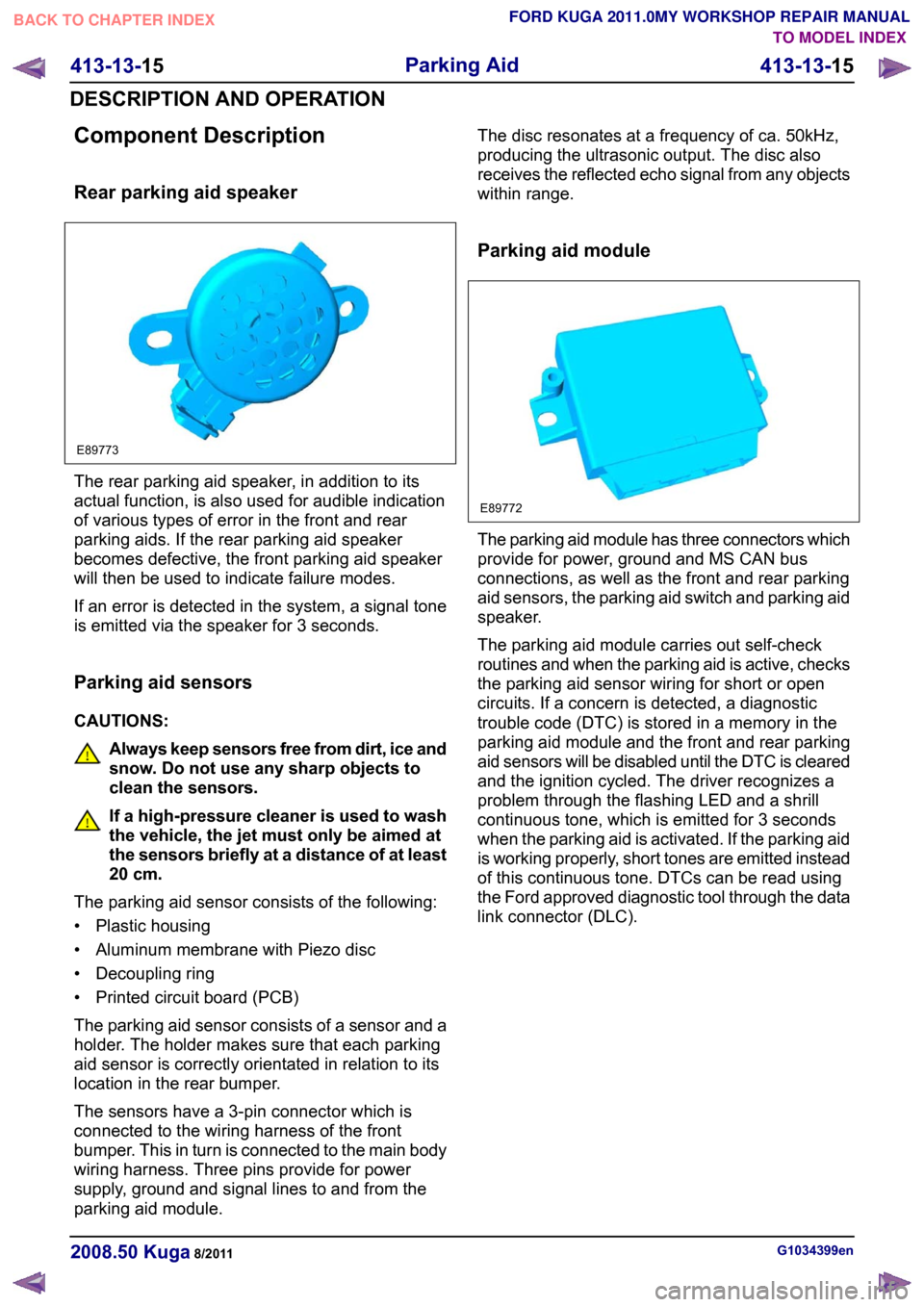
Component Description
Rear parking aid speaker
The rear parking aid speaker, in addition to its
actual function, is also used for audible indication
of various types of error in the front and rear
parking aids. If the rear parking aid speaker
becomes defective, the front parking aid speaker
will then be used to indicate failure modes.
If an error is detected in the system, a signal tone
is emitted via the speaker for 3 seconds.
Parking aid sensors
CAUTIONS:
Always keep sensors free from dirt, ice and
snow. Do not use any sharp objects to
clean the sensors.
If a high-pressure cleaner is used to wash
the vehicle, the jet must only be aimed at
the sensors briefly at a distance of at least
20 cm.
The parking aid sensor consists of the following:
• Plastic housing
• Aluminum membrane with Piezo disc
• Decoupling ring
• Printed circuit board (PCB)
The parking aid sensor consists of a sensor and a
holder. The holder makes sure that each parking
aid sensor is correctly orientated in relation to its
location in the rear bumper.
The sensors have a 3-pin connector which is
connected to the wiring harness of the front
bumper. This in turn is connected to the main body
wiring harness. Three pins provide for power
supply, ground and signal lines to and from the
parking aid module. The disc resonates at a frequency of ca. 50kHz,
producing the ultrasonic output. The disc also
receives the reflected echo signal from any objects
within range.
Parking aid module
The parking aid module has three connectors which
provide for power, ground and MS CAN bus
connections, as well as the front and rear parking
aid sensors, the parking aid switch and parking aid
speaker.
The parking aid module carries out self-check
routines and when the parking aid is active, checks
the parking aid sensor wiring for short or open
circuits. If a concern is detected, a diagnostic
trouble code (DTC) is stored in a memory in the
parking aid module and the front and rear parking
aid sensors will be disabled until the DTC is cleared
and the ignition cycled. The driver recognizes a
problem through the flashing LED and a shrill
continuous tone, which is emitted for 3 seconds
when the parking aid is activated. If the parking aid
is working properly, short tones are emitted instead
of this continuous tone. DTCs can be read using
the Ford approved diagnostic tool through the data
link connector (DLC).
G1034399en
2008.50 Kuga 8/2011 413-13-15
Parking Aid
413-13-15
DESCRIPTION AND OPERATIONTO MODEL INDEX
BACK TO CHAPTER INDEX
FORD KUGA 2011.0MY WORKSHOP REPAIR MANUALE89773 E89772
Page 216 of 2057
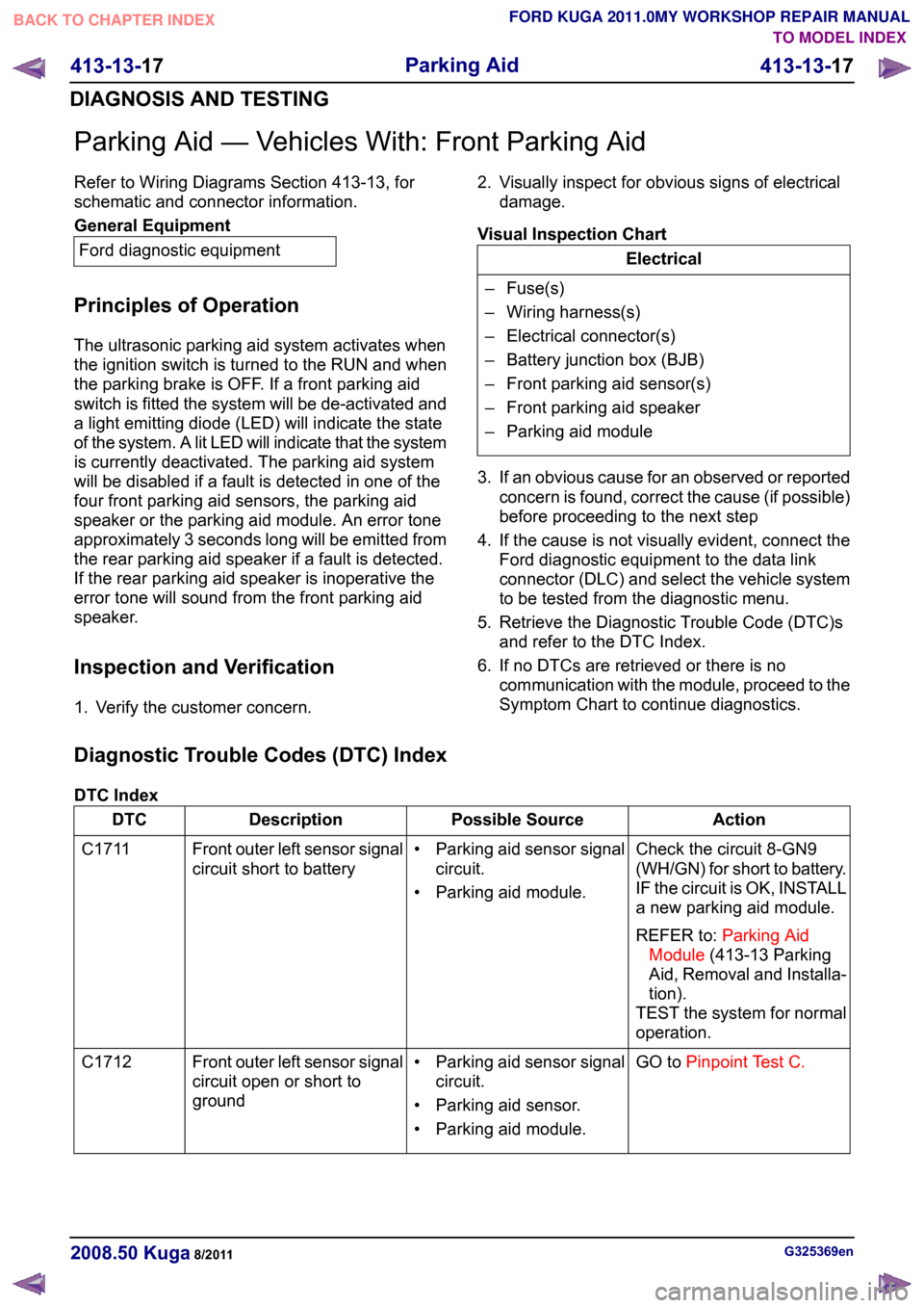
Parking Aid — Vehicles With: Front Parking Aid
Refer to Wiring Diagrams Section 413-13, for
schematic and connector information.
General Equipment
Ford diagnostic equipment
Principles of Operation
The ultrasonic parking aid system activates when
the ignition switch is turned to the RUN and when
the parking brake is OFF. If a front parking aid
switch is fitted the system will be de-activated and
a light emitting diode (LED) will indicate the state
of the system. A lit LED will indicate that the system
is currently deactivated. The parking aid system
will be disabled if a fault is detected in one of the
four front parking aid sensors, the parking aid
speaker or the parking aid module. An error tone
approximately 3 seconds long will be emitted from
the rear parking aid speaker if a fault is detected.
If the rear parking aid speaker is inoperative the
error tone will sound from the front parking aid
speaker.
Inspection and Verification
1. Verify the customer concern. 2. Visually inspect for obvious signs of electrical
damage.
Visual Inspection Chart Electrical
– Fuse(s)
– Wiring harness(s)
– Electrical connector(s)
– Battery junction box (BJB)
– Front parking aid sensor(s)
– Front parking aid speaker
– Parking aid module
3. If an obvious cause for an observed or reported concern is found, correct the cause (if possible)
before proceeding to the next step
4. If the cause is not visually evident, connect the Ford diagnostic equipment to the data link
connector (DLC) and select the vehicle system
to be tested from the diagnostic menu.
5. Retrieve the Diagnostic Trouble Code (DTC)s and refer to the DTC Index.
6. If no DTCs are retrieved or there is no communication with the module, proceed to the
Symptom Chart to continue diagnostics.
Diagnostic Trouble Codes (DTC) Index
DTC Index Action
Possible Source
Description
DTC
Check the circuit 8-GN9
(WH/GN) for short to battery.
IF the circuit is OK, INSTALL
a new parking aid module.
REFER to:Parking Aid
Module (413-13 Parking
Aid, Removal and Installa-
tion).
TEST the system for normal
operation.
• Parking aid sensor signal
circuit.
• Parking aid module.
Front outer left sensor signal
circuit short to battery
C1711
GO toPinpoint Test C.
• Parking aid sensor signal
circuit.
• Parking aid sensor.
• Parking aid module.
Front outer left sensor signal
circuit open or short to
ground
C1712 G325369en
2008.50 Kuga 8/2011 413-13-17
Parking Aid
413-13-17
DIAGNOSIS AND TESTINGTO MODEL INDEX
BACK TO CHAPTER INDEX
FORD KUGA 2011.0MY WORKSHOP REPAIR MANUAL
Page 228 of 2057
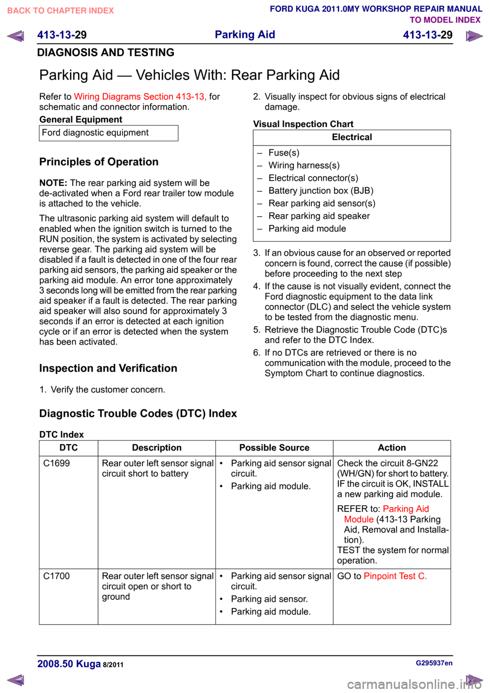
Parking Aid — Vehicles With: Rear Parking Aid
Refer to
Wiring Diagrams Section 413-13, for
schematic and connector information. General Equipment
Ford diagnostic equipment
Principles of Operation
NOTE: The rear parking aid system will be
de-activated when a Ford rear trailer tow module
is attached to the vehicle.
The ultrasonic parking aid system will default to
enabled when the ignition switch is turned to the
RUN position, the system is activated by selecting
reverse gear. The parking aid system will be
disabled if a fault is detected in one of the four rear
parking aid sensors, the parking aid speaker or the
parking aid module. An error tone approximately
3 seconds long will be emitted from the rear parking
aid speaker if a fault is detected. The rear parking
aid speaker will also sound for approximately 3
seconds if an error is detected at each ignition
cycle or if an error is detected when the system
has been activated.
Inspection and Verification
1. Verify the customer concern. 2. Visually inspect for obvious signs of electrical
damage.
Visual Inspection Chart Electrical
– Fuse(s)
– Wiring harness(s)
– Electrical connector(s)
– Battery junction box (BJB)
– Rear parking aid sensor(s)
– Rear parking aid speaker
– Parking aid module
3. If an obvious cause for an observed or reported concern is found, correct the cause (if possible)
before proceeding to the next step
4. If the cause is not visually evident, connect the Ford diagnostic equipment to the data link
connector (DLC) and select the vehicle system
to be tested from the diagnostic menu.
5. Retrieve the Diagnostic Trouble Code (DTC)s and refer to the DTC Index.
6. If no DTCs are retrieved or there is no communication with the module, proceed to the
Symptom Chart to continue diagnostics.
Diagnostic Trouble Codes (DTC) Index
DTC Index Action
Possible Source
Description
DTC
Check the circuit 8-GN22
(WH/GN) for short to battery.
IF the circuit is OK, INSTALL
a new parking aid module.
REFER to:Parking Aid
Module (413-13 Parking
Aid, Removal and Installa-
tion).
TEST the system for normal
operation.
• Parking aid sensor signal
circuit.
• Parking aid module.
Rear outer left sensor signal
circuit short to battery
C1699
GO toPinpoint Test C.
• Parking aid sensor signal
circuit.
• Parking aid sensor.
• Parking aid module.
Rear outer left sensor signal
circuit open or short to
ground
C1700 G295937en
2008.50 Kuga 8/2011 413-13-29
Parking Aid
413-13-29
DIAGNOSIS AND TESTINGTO MODEL INDEX
BACK TO CHAPTER INDEX
FORD KUGA 2011.0MY WORKSHOP REPAIR MANUAL
Page 263 of 2057
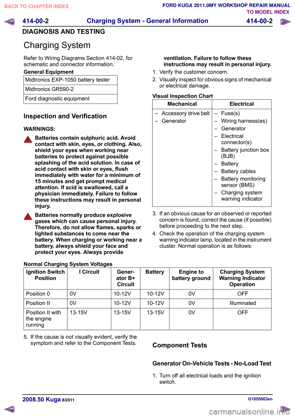
Charging System
Refer to Wiring Diagrams Section 414-02, for
schematic and connector information.
General Equipment
Midtronics EXP-1050 battery tester
Midtronics GR590-2
Ford diagnostic equipment
Inspection and Verification
WARNINGS: Batteries contain sulphuric acid. Avoid
contact with skin, eyes, or clothing. Also,
shield your eyes when working near
batteries to protect against possible
splashing of the acid solution. In case of
acid contact with skin or eyes, flush
immediately with water for a minimum of
15 minutes and get prompt medical
attention. If acid is swallowed, call a
physician immediately. Failure to follow
these instructions may result in personal
injury.
Batteries normally produce explosive
gases which can cause personal injury.
Therefore, do not allow flames, sparks or
lighted substances to come near the
battery. When charging or working near a
battery, always shield your face and
protect your eyes. Always provide
ventilation. Failure to follow these
instructions may result in personal injury.
1. Verify the customer concern.
2. Visually inspect for obvious signs of mechanical
or electrical damage.
Visual Inspection Chart Electrical
Mechanical
– Fuse(s)
– Wiring harness(es)
– Generator
– Electricalconnector(s)
– Battery junction box (BJB)
– Battery
– Battery cables
– Battery monitoring sensor (BMS)
– Charging system warning indicator
–
Accessory drive belt
– Generator
3. If an obvious cause for an observed or reported concern is found, correct the cause (if possible)
before proceeding to the next step.
4. Check the operation of the charging system warning indicator lamp, located in the instrument
cluster. Normal operation is as follows:
Normal Charging System Voltages Charging System
Warning Indicator Operation
Engine to
battery ground
Battery
Gener-
ator B+ Circuit
I Circuit
Ignition Switch
Position
OFF
0V
10-12V
10-12V
0V
Position 0
Illuminated
0V
10-12V
10-12V
0V
Position II
OFF
0V
13-15V
13-15V
13-15V
Position II with
the engine
running
5. If the cause is not visually evident, verify the symptom and refer to the Component Tests. Component Tests
Generator On-Vehicle Tests - No-Load Test
1. Turn off all electrical loads and the ignition
switch. G1055063en
2008.50 Kuga 8/2011 414-00-2
Charging System - General Information
414-00-2
DIAGNOSIS AND TESTINGTO MODEL INDEX
BACK TO CHAPTER INDEX
FORD KUGA 2011.0MY WORKSHOP REPAIR MANUAL
Page 279 of 2057

Direct Current/Alternating Current (DC/AC) Inverter – Overview
Function indicator
WARNING: For workshop repairs, it is only
permissible to replace the converter as a
complete unit together with the wiring
harness and the socket. The component
must not be opened, as charged capacitors
inside can still carry dangerously high
residual voltages.
The LED in the socket lights up orange when the
converter is supplying a voltage.
In the event of a fault the system switches off and
indicates the cause of the fault by flashing a trouble
code via the LED in the socket:
• 1x flash – High temperature
• 2x flashes – Overload
• 3x flashes – Internal overvoltage
• 4x flashes – Internal undervoltage
• Continuous flashing – Short circuit to power
If the converter switches off due to high
temperature then it switches back on again
automatically once the temperature has cooled
down sufficiently.
With all of the other faults which are displayed, the
converter can be reset by switching the ignition off
and back on again or by unplugging and reinserting
the consumer in the socket.
If these measures are unsuccessful then there are
no further options for directly influencing the
function yourself. G1055637en
2008.50 Kuga 8/2011 414-05-3
Voltage Converter/Inverter
414-05-3
DESCRIPTION AND OPERATIONTO MODEL INDEX
BACK TO CHAPTER INDEX
FORD KUGA 2011.0MY WORKSHOP REPAIR MANUAL
Page 280 of 2057
Direct Current/Alternating Current (DC/AC) Inverter – System
Operation and Component Description
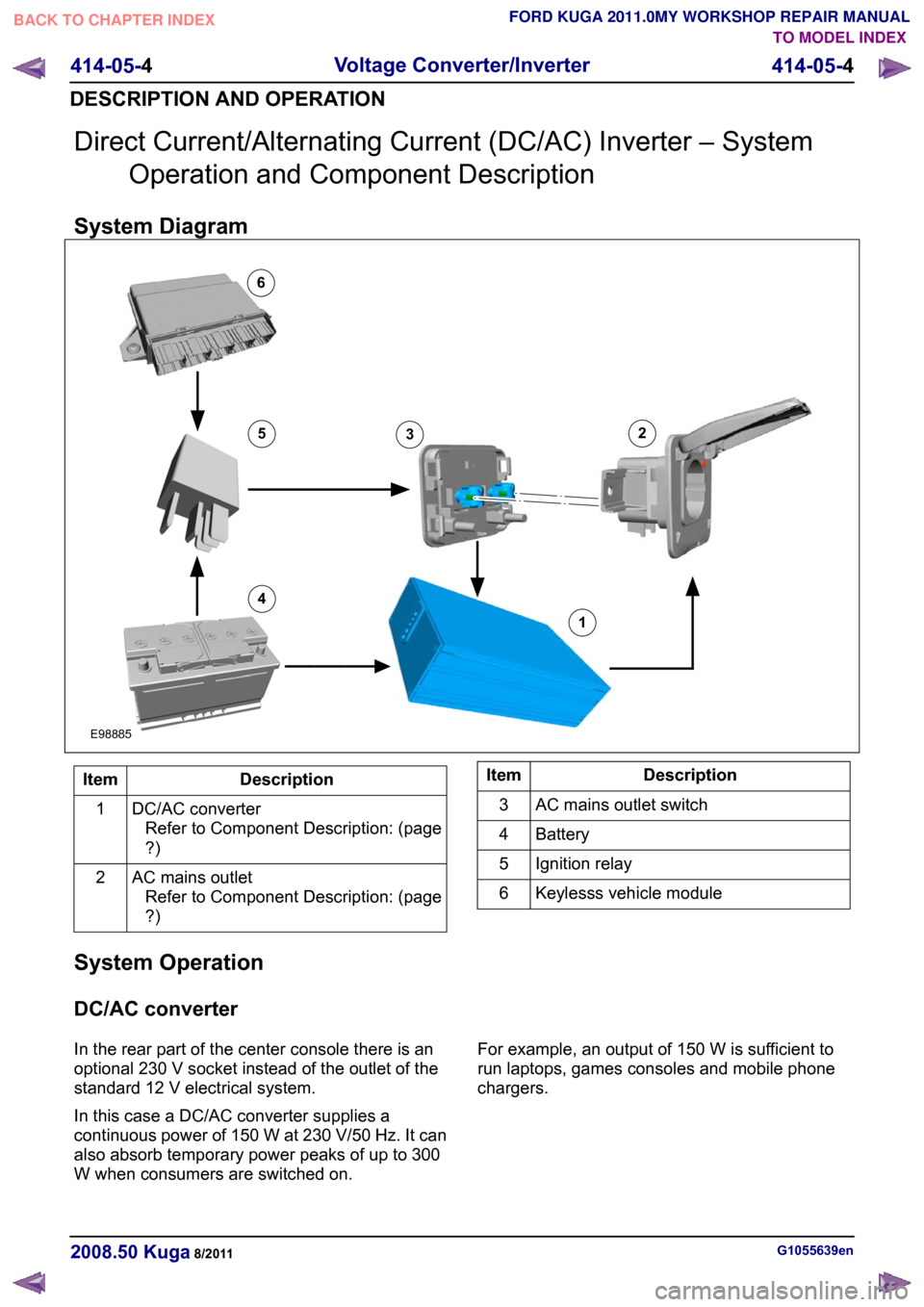
System Diagram Description
Item
DC/AC converterRefer to Component Description: (page
?)
1
AC mains outletRefer to Component Description: (page
?)
2 Description
Item
AC mains outlet switch
3
Battery
4
Ignition relay
5
Keylesss vehicle module
6
System Operation
DC/AC converter
In the rear part of the center console there is an
optional 230 V socket instead of the outlet of the
standard 12 V electrical system.
In this case a DC/AC converter supplies a
continuous power of 150 W at 230 V/50 Hz. It can
also absorb temporary power peaks of up to 300
W when consumers are switched on. For example, an output of 150 W is sufficient to
run laptops, games consoles and mobile phone
chargers.
G1055639en
2008.50 Kuga 8/2011 414-05-4
Voltage Converter/Inverter
414-05-4
DESCRIPTION AND OPERATIONTO MODEL INDEX
BACK TO CHAPTER INDEX
FORD KUGA 2011.0MY WORKSHOP REPAIR MANUAL12456E988853
Page 281 of 2057
Component Description
DC/AC converter
The converter operates with a series connection
of two power converter circuits. The primary power
converter here is a push-pull converter. It converts
the 12 V supply from the electrical system of the
vehicle to an intermediate direct current link of
approx. 320 V.
From this intermediate direct current link, the
downstream full H-bridge circuit generates a
pulse-width modulated output voltage with 230
V/50 Hz.
A controller modulates the pulse width of the
square-wave output voltage and maintains an
effective output voltage of 230 V under varying
load conditions and under different input voltages.
Here, the rising and falling edge of the positive and
negative square wave pulse are controlled
symmetrically to the ideal shape of a sine wave,
which - among other things - also makes a positive
contribution to electromagnetic compatibility.
DC/AC converters which supply a modified square
wave output voltage are referred to as 'Modified
Sine Wave Inverters".
With this type of system there is no need for a
residual current operated device for protection in
the event of accidental contact, as all of the 230 V
lines are double-insulated. Potential-free separation
of the entire 230 V voltage part from the vehicle is
provided (electrical isolation).
The output voltage of 230 V/50 Hz is not generated
until the switching voltage is present at terminal 1
of the converter via the AC mains outlet switch.
The converter operates with the ignition switched
on and a vehicle electrical supply of between 11
V and 16 V. Internal voltage monitoring in the converter deactivates the system if the input
voltage is outside this range.
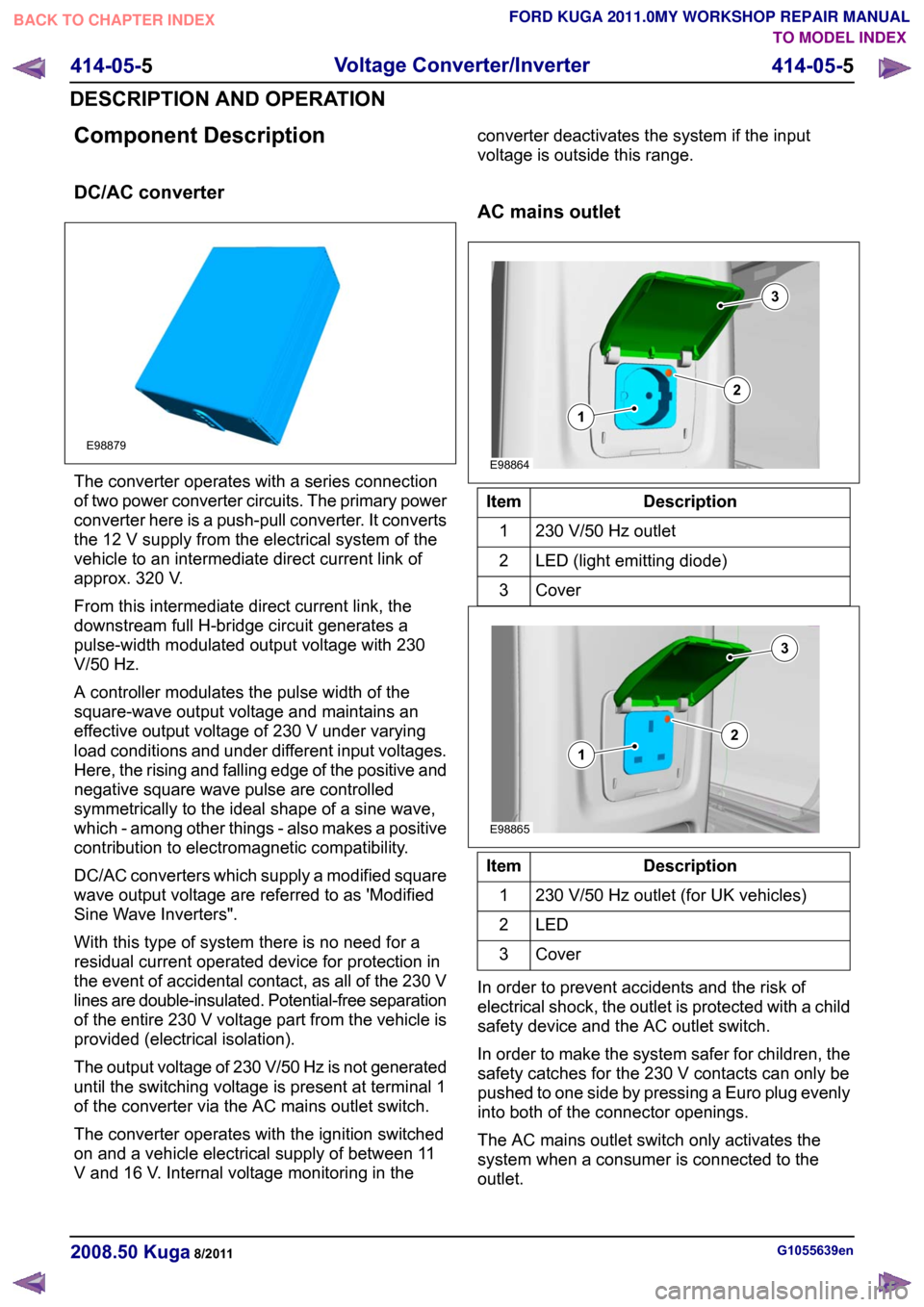
AC mains outlet
Description
Item
230 V/50 Hz outlet
1
LED (light emitting diode)
2
Cover3 Description
Item
230 V/50 Hz outlet (for UK vehicles)
1
LED2
Cover3
In order to prevent accidents and the risk of
electrical shock, the outlet is protected with a child
safety device and the AC outlet switch.
In order to make the system safer for children, the
safety catches for the 230 V contacts can only be
pushed to one side by pressing a Euro plug evenly
into both of the connector openings.
The AC mains outlet switch only activates the
system when a consumer is connected to the
outlet. G1055639en
2008.50 Kuga 8/2011 414-05-5
Voltage Converter/Inverter
414-05-5
DESCRIPTION AND OPERATIONTO MODEL INDEX
BACK TO CHAPTER INDEX
FORD KUGA 2011.0MY WORKSHOP REPAIR MANUALE98879 E98864312 E98865312
Page 299 of 2057
Audio System – Overview
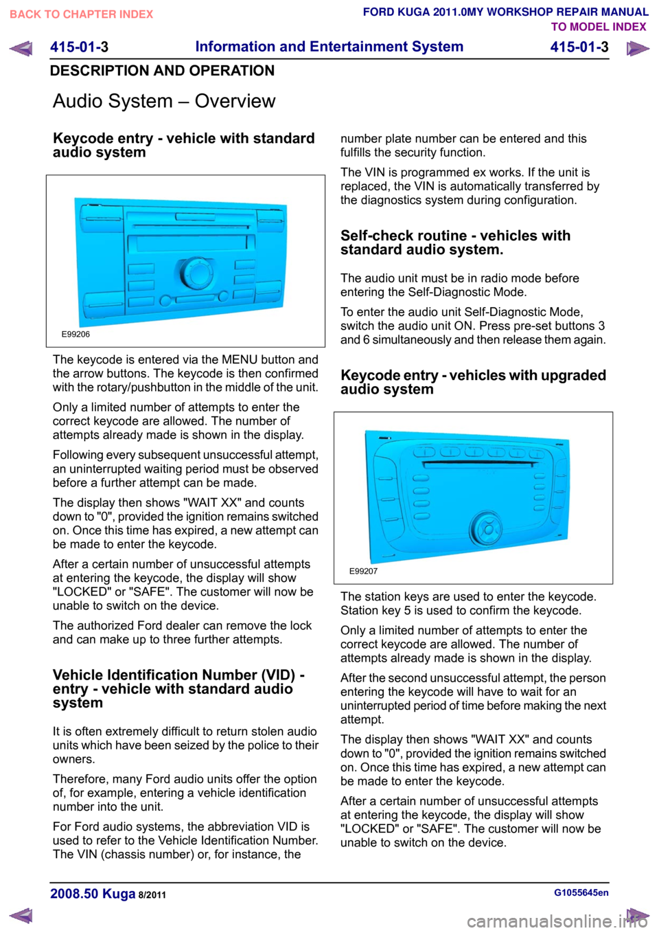
Keycode entry - vehicle with standard
audio system
The keycode is entered via the MENU button and
the arrow buttons. The keycode is then confirmed
with the rotary/pushbutton in the middle of the unit.
Only a limited number of attempts to enter the
correct keycode are allowed. The number of
attempts already made is shown in the display.
Following every subsequent unsuccessful attempt,
an uninterrupted waiting period must be observed
before a further attempt can be made.
The display then shows "WAIT XX" and counts
down to "0", provided the ignition remains switched
on. Once this time has expired, a new attempt can
be made to enter the keycode.
After a certain number of unsuccessful attempts
at entering the keycode, the display will show
"LOCKED" or "SAFE". The customer will now be
unable to switch on the device.
The authorized Ford dealer can remove the lock
and can make up to three further attempts.
Vehicle Identification Number (VID) -
entry - vehicle with standard audio
system
It is often extremely difficult to return stolen audio
units which have been seized by the police to their
owners.
Therefore, many Ford audio units offer the option
of, for example, entering a vehicle identification
number into the unit.
For Ford audio systems, the abbreviation VID is
used to refer to the Vehicle Identification Number.
The VIN (chassis number) or, for instance, the number plate number can be entered and this
fulfills the security function.
The VIN is programmed ex works. If the unit is
replaced, the VIN is automatically transferred by
the diagnostics system during configuration.
Self-check routine - vehicles with
standard audio system.
The audio unit must be in radio mode before
entering the Self-Diagnostic Mode.
To enter the audio unit Self-Diagnostic Mode,
switch the audio unit ON. Press pre-set buttons 3
and 6 simultaneously and then release them again.
Keycode entry - vehicles with upgraded
audio system
The station keys are used to enter the keycode.
Station key 5 is used to confirm the keycode.
Only a limited number of attempts to enter the
correct keycode are allowed. The number of
attempts already made is shown in the display.
After the second unsuccessful attempt, the person
entering the keycode will have to wait for an
uninterrupted period of time before making the next
attempt.
The display then shows "WAIT XX" and counts
down to "0", provided the ignition remains switched
on. Once this time has expired, a new attempt can
be made to enter the keycode.
After a certain number of unsuccessful attempts
at entering the keycode, the display will show
"LOCKED" or "SAFE". The customer will now be
unable to switch on the device.
G1055645en
2008.50 Kuga 8/2011 415-01-3
Information and Entertainment System
415-01-3
DESCRIPTION AND OPERATIONTO MODEL INDEX
BACK TO CHAPTER INDEX
FORD KUGA 2011.0MY WORKSHOP REPAIR MANUALE99206 E99207
Page 341 of 2057
Combined rain sensor/light sensor
CAUTIONS:
On vehicles with autolamps, retrofitting
with daytime running lamps is not
permissible, as otherwise, the engine
cannot be stopped when the lighting is
switched on.
On vehicles with autolamps, the daytime
running lamp fuse must not be fitted, as
otherwise, the engine cannot be stopped
when the lighting is switched on.
The combined rain sensor/light sensor is located
behind the interior rear view mirror.
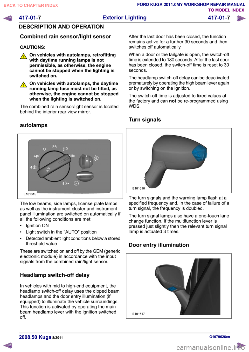
autolamps The low beams, side lamps, license plate lamps
as well as the instrument cluster and instrument
panel illumination are switched on automatically if
all the following conditions are met:
• Ignition ON
• Light switch in the "AUTO" position
•
Detected ambient light conditions below a stored
threshold value
These are switched on and off by the GEM (generic
electronic module) in accordance with the input
signals from the combined rain/light sensor.
Headlamp switch-off delay
In vehicles with mid to high-end equipment, the
headlamp switch-off delay uses the dipped beam
headlamps and the door entry illumination (if
equipped) to illuminate the vehicle surroundings.
This function is activated by operating the main
beam headlamp lever with the ignition switched
off. After the last door has been closed, the function
remains active for a further 30 seconds and then
switches off automatically.
When a door or the tailgate is open, the switch-off
time is extended to 180 seconds. After the last door
has been closed, the switch-off time is reset to 30
seconds.
The headlamp switch-off delay can be deactivated
prematurely by operating the high beam lever again
or by switching on the ignition.
The switch-off time is adjusted to fixed values at
the factory and can
notbe re-programmed using
WDS.
Turn signals The turn signals and the warning lamp flash at a
specified frequency and, in the case of failure of a
turn signal, the frequency is doubled.
The turn signal lamps also have a one-touch lane
change function. If the multifunction lever is
pressed just slightly then the relevant turn signal
lamp is actuated 3 times.
Door entry illumination
G1079626en
2008.50 Kuga 8/2011 417-01-7
Exterior Lighting
417-01-7
DESCRIPTION AND OPERATIONTO MODEL INDEX
BACK TO CHAPTER INDEX
FORD KUGA 2011.0MY WORKSHOP REPAIR MANUALE101615 E101616 E101617