steering system FORD KUGA 2011 1.G User Guide
[x] Cancel search | Manufacturer: FORD, Model Year: 2011, Model line: KUGA, Model: FORD KUGA 2011 1.GPages: 2057
Page 87 of 2057
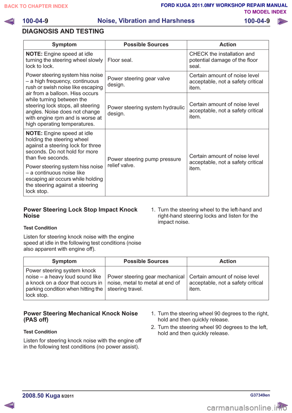
Action
Possible Sources
Symptom
CHECK the installation and
potential damage of the floor
seal.
Floor seal.
NOTE:
Engine speed at idle
turning the steering wheel slowly
lock to lock.
Power steering system hiss noise
– a high frequency, continuous
rush or swish noise like escaping
air from a balloon. Hiss occurs
while turning between the
steering lock stops, all steering
angles. Noise does not change
with engine rpm and is worse at
high operating temperatures. Certain amount of noise level
acceptable, not a safety critical
item.
Power steering gear valve
design.
Certain amount of noise level
acceptable, not a safety critical
item.
Power steering system hydraulic
design.
Certain amount of noise level
acceptable, not a safety critical
item.
Power steering pump pressure
relief valve.
NOTE:
Engine speed at idle
holding the steering wheel
against a steering lock for three
seconds. Do not hold for more
than five seconds.
Power steering system hiss noise
– a continuous noise like
escaping air occurs while holding
the steering against a steering
lock stop.
Power Steering Lock Stop Impact Knock
Noise
Test Condition
Listen for steering knock noise with the engine
speed at idle in the following test conditions (noise
also apparent with engine off). 1. Turn the steering wheel to the left-hand and
right-hand steering locks and listen for the
impact noise.
Action
Possible Sources
Symptom
Certain amount of noise level
acceptable, not a safety critical
item.
Power steering gear mechanical
noise, metal to metal at end of
steering travel.
Power steering system knock
noise – a heavy loud sound like
a knock on a door that occurs in
parking condition when hitting the
lock stop.
Power Steering Mechanical Knock Noise
(PAS off)
Test Condition
Listen for steering knock noise with the engine off
in the following test conditions (no power assist). 1. Turn the steering wheel 90 degrees to the right,
hold and then quickly release.
2. Turn the steering wheel 90 degrees to the left, hold and then quickly release.
G37349en2008.50 Kuga8/2011
100-04- 9
Noise, Vibration and Harshness
100-04- 9
DIAGNOSIS AND TESTING
TO MODEL INDEX
BACK TO CHAPTER INDEX
FORD KUGA 2011.0MY WORKSHOP REPAIR MANUAL
Page 88 of 2057
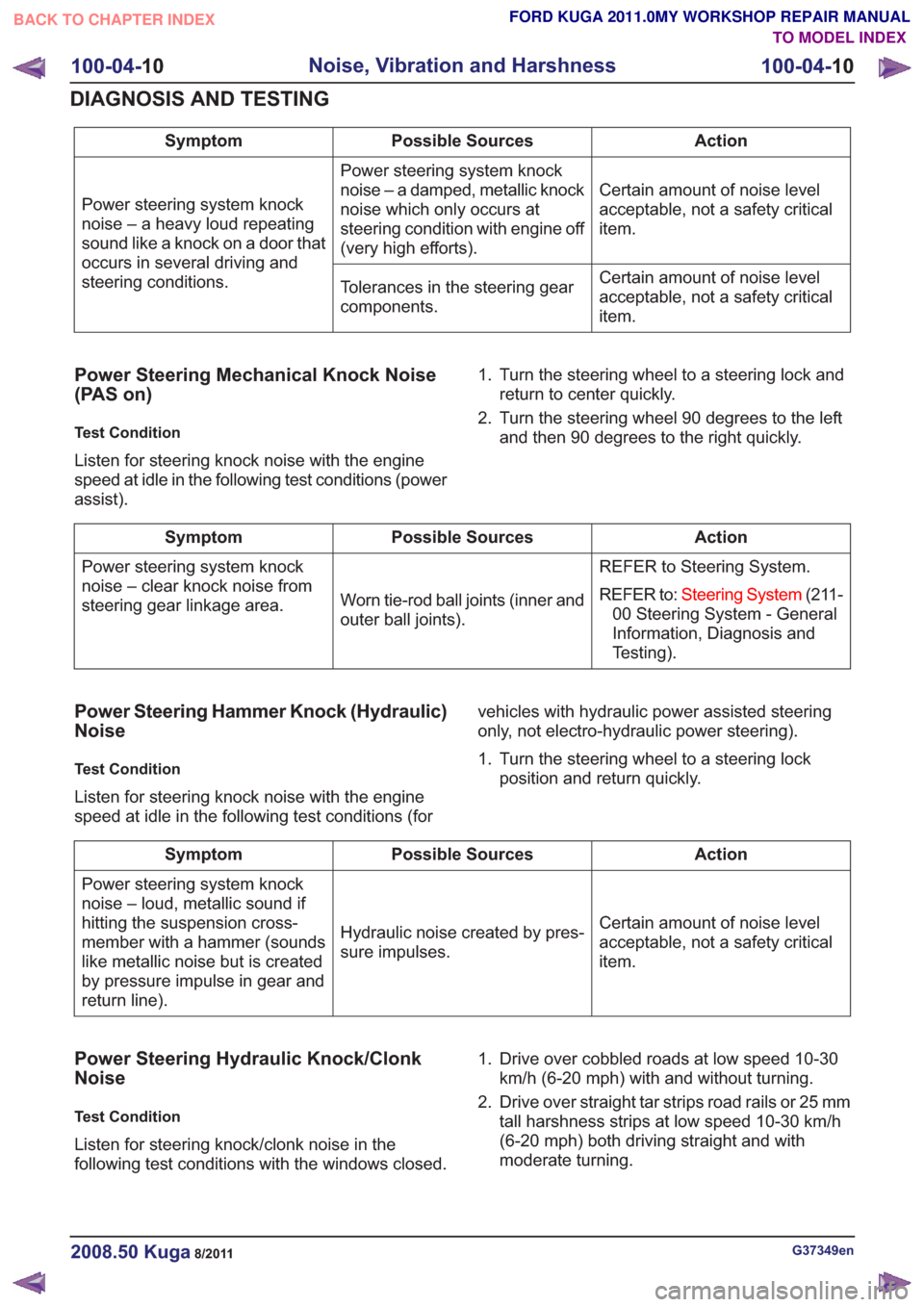
Action
Possible Sources
Symptom
Certain amount of noise level
acceptable, not a safety critical
item.
Power steering system knock
noise – a damped, metallic knock
noise which only occurs at
steering condition with engine off
(very high efforts).
Power steering system knock
noise – a heavy loud repeating
sound like a knock on a door that
occurs in several driving and
steering conditions.
Certain amount of noise level
acceptable, not a safety critical
item.
Tolerances in the steering gear
components.
Power Steering Mechanical Knock Noise
(PAS on)
Test Condition
Listen for steering knock noise with the engine
speed at idle in the following test conditions (power
assist). 1. Turn the steering wheel to a steering lock and
return to center quickly.
2. Turn the steering wheel 90 degrees to the left and then 90 degrees to the right quickly.
Action
Possible Sources
Symptom
REFER to Steering System.
REFER to:Steering System (211-
00 Steering System - General
Information, Diagnosis and
Testing).
Worn tie-rod ball joints (inner and
outer ball joints).
Power steering system knock
noise – clear knock noise from
steering gear linkage area.
Power Steering Hammer Knock (Hydraulic)
Noise
Test Condition
Listen for steering knock noise with the engine
speed at idle in the following test conditions (for vehicles with hydraulic power assisted steering
only, not electro-hydraulic power steering).
1. Turn the steering wheel to a steering lock
position and return quickly.
Action
Possible Sources
Symptom
Certain amount of noise level
acceptable, not a safety critical
item.
Hydraulic noise created by pres-
sure impulses.
Power steering system knock
noise – loud, metallic sound if
hitting the suspension cross-
member with a hammer (sounds
like metallic noise but is created
by pressure impulse in gear and
return line).
Power Steering Hydraulic Knock/Clonk
Noise
Test Condition
Listen for steering knock/clonk noise in the
following test conditions with the windows closed. 1. Drive over cobbled roads at low speed 10-30
km/h (6-20 mph) with and without turning.
2. Drive over straight tar strips road rails or 25 mm tall harshness strips at low speed 10-30 km/h
(6-20 mph) both driving straight and with
moderate turning.
G37349en2008.50 Kuga8/2011
100-04- 10
Noise, Vibration and Harshness
100-04- 10
DIAGNOSIS AND TESTING
TO MODEL INDEX
BACK TO CHAPTER INDEX
FORD KUGA 2011.0MY WORKSHOP REPAIR MANUAL
Page 89 of 2057
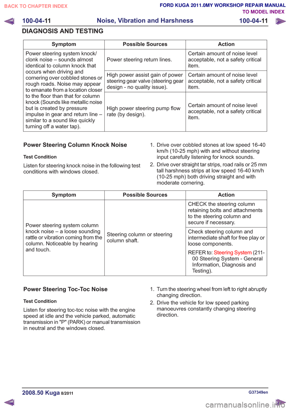
Action
Possible Sources
Symptom
Certain amount of noise level
acceptable, not a safety critical
item.
Power steering return lines.
Power steering system knock/
clonk noise – sounds almost
identical to column knock that
occurs when driving and
cornering over cobbled stones or
rough roads. Noise may appear
to emanate from a location closer
to the floor than that for column
knock (Sounds like metallic noise
but is created by pressure
impulse in gear and return line –
similar to a sound like quickly
turning off a water tap). Certain amount of noise level
acceptable, not a safety critical
item.
High power assist gain of power
steering gear valve (steering gear
design - no quality issue).
Certain amount of noise level
acceptable, not a safety critical
item.
High power steering pump flow
rate (by design).
Power Steering Column Knock Noise
Test Condition
Listen for steering knock noise in the following test
conditions with windows closed. 1. Drive over cobbled stones at low speed 16-40
km/h (10-25 mph) with and without steering
input carefully listening for knock sounds.
2. Drive over straight tar strips, road rails or 25 mm tall harshness strips at low speed 16-40 km/h
(10-25 mph) both driving straight and with
moderate cornering.
Action
Possible Sources
Symptom
CHECK the steering column
retaining bolts and attachments
to the steering column and
secure if necessary.
Steering column or steering
column shaft.
Power steering system column
knock noise – a loose sounding
rattle or vibration coming from the
column. Noticeable by hearing
and touch. Check steering column and
intermediate shaft for free play or
loose components.
REFER to:
Steering System (211-
00 Steering System - General
Information, Diagnosis and
Testing).
Power Steering Toc-Toc Noise
Test Condition
Listen for steering toc-toc noise with the engine
speed at idle and the vehicle parked, automatic
transmission in "P" (PARK) or manual transmission
in neutral and the windows closed. 1. Turn the steering wheel from left to right abruptly
changing direction.
2. Drive the vehicle for low speed parking manoeuvres constantly changing steering
direction.
G37349en2008.50 Kuga8/2011
100-04- 11
Noise, Vibration and Harshness
100-04- 11
DIAGNOSIS AND TESTING
TO MODEL INDEX
BACK TO CHAPTER INDEX
FORD KUGA 2011.0MY WORKSHOP REPAIR MANUAL
Page 90 of 2057
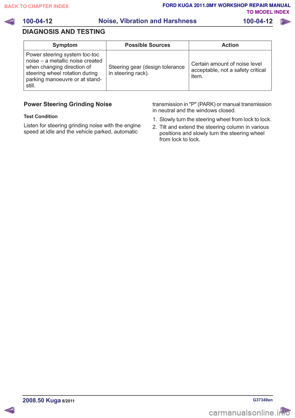
Action
Possible Sources
Symptom
Certain amount of noise level
acceptable, not a safety critical
item.
Steering gear (design tolerance
in steering rack).
Power steering system toc-toc
noise – a metallic noise created
when changing direction of
steering wheel rotation during
parking manoeuvre or at stand-
still.
Power Steering Grinding Noise
Test Condition
Listen for steering grinding noise with the engine
speed at idle and the vehicle parked, automatic transmission in "P" (PARK) or manual transmission
in neutral and the windows closed.
1. Slowly turn the steering wheel from lock to lock.
2. Tilt and extend the steering column in various
positions and slowly turn the steering wheel
from lock to lock.
G37349en2008.50 Kuga8/2011
100-04- 12
Noise, Vibration and Harshness
100-04- 12
DIAGNOSIS AND TESTING
TO MODEL INDEX
BACK TO CHAPTER INDEX
FORD KUGA 2011.0MY WORKSHOP REPAIR MANUAL
Page 91 of 2057
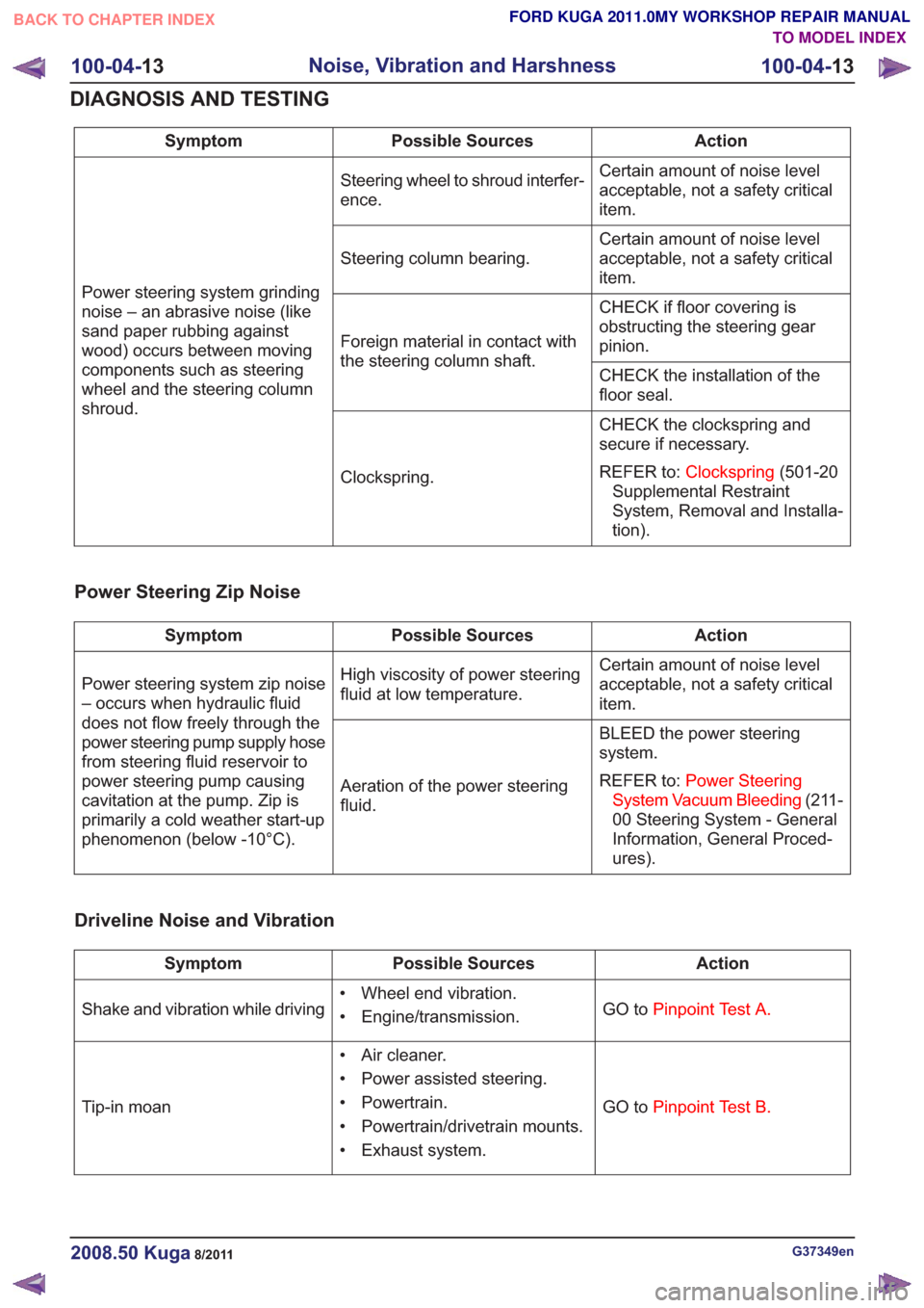
Action
Possible Sources
Symptom
Certain amount of noise level
acceptable, not a safety critical
item.
Steering wheel to shroud interfer-
ence.
Power steering system grinding
noise – an abrasive noise (like
sand paper rubbing against
wood) occurs between moving
components such as steering
wheel and the steering column
shroud. Certain amount of noise level
acceptable, not a safety critical
item.
Steering column bearing.
CHECK if floor covering is
obstructing the steering gear
pinion.
Foreign material in contact with
the steering column shaft.
CHECK the installation of the
floor seal.
CHECK the clockspring and
secure if necessary.
REFER to:Clockspring (501-20
Supplemental Restraint
System, Removal and Installa-
tion).
Clockspring.
Power Steering Zip Noise
Action
Possible Sources
Symptom
Certain amount of noise level
acceptable, not a safety critical
item.
High viscosity of power steering
fluid at low temperature.
Power steering system zip noise
– occurs when hydraulic fluid
does not flow freely through the
power steering pump supply hose
from steering fluid reservoir to
power steering pump causing
cavitation at the pump. Zip is
primarily a cold weather start-up
phenomenon (below -10°C). BLEED the power steering
system.
REFER to:
Power Steering
System Vacuum Bleeding (211-
00 Steering System - General
Information, General Proced-
ures).
Aeration of the power steering
fluid.
Driveline Noise and Vibration
Action
Possible Sources
Symptom
GO toPinpoint Test A.
• Wheel end vibration.
• Engine/transmission.
Shake and vibration while driving
GO toPinpoint Test B.
• Air cleaner.
• Power assisted steering.
• Powertrain.
• Powertrain/drivetrain mounts.
• Exhaust system.
Tip-in moan
G37349en2008.50 Kuga8/2011
100-04-
13
Noise, Vibration and Harshness
100-04- 13
DIAGNOSIS AND TESTING
TO MODEL INDEX
BACK TO CHAPTER INDEX
FORD KUGA 2011.0MY WORKSHOP REPAIR MANUAL
Page 93 of 2057
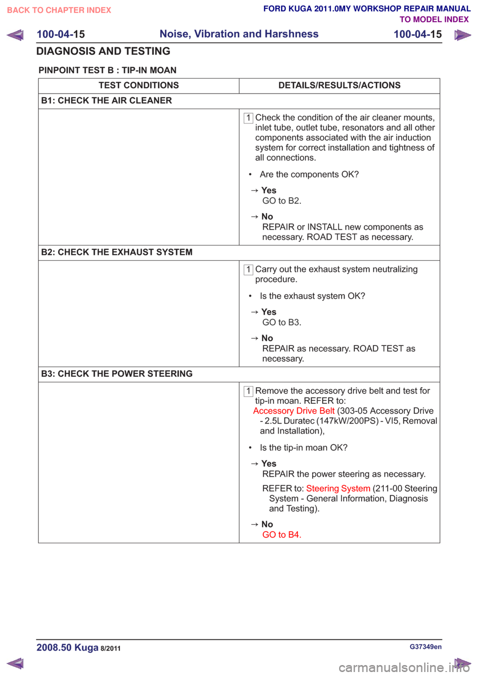
PINPOINT TEST B : TIP-IN MOAN
DETAILS/RESULTS/ACTIONS
TEST CONDITIONS
B1: CHECK THE AIR CLEANER
1 Check the condition of the air cleaner mounts,
inlet tube, outlet tube, resonators and all other
components associated with the air induction
system for correct installation and tightness of
all connections.
• Are the components OK?
zYe s GO to B2.
zNoREPAIR or INSTALL new components as
necessary. ROAD TEST as necessary.
B2: CHECK THE EXHAUST SYSTEM
1 Carry out the exhaust system neutralizing
procedure.
• Is the exhaust system OK?
zYe s GO to B3.
zNoREPAIR as necessary. ROAD TEST as
necessary.
B3: CHECK THE POWER STEERING
1 Remove the accessory drive belt and test for
tip-in moan. REFER to:
Accessory Drive Belt (303-05 Accessory Drive
- 2.5L Duratec (147kW/200PS) - VI5, Removal
and Installation),
• Is the tip-in moan OK?
zYe s REPAIR the power steering as necessary.
REFER to: Steering System (211-00 Steering
System - General Information, Diagnosis
and Testing).
zNo
GO to B4.
G37349en2008.50 Kuga8/2011
100-04- 15
Noise, Vibration and Harshness
100-04- 15
DIAGNOSIS AND TESTING
TO MODEL INDEX
BACK TO CHAPTER INDEX
FORD KUGA 2011.0MY WORKSHOP REPAIR MANUAL
Page 100 of 2057
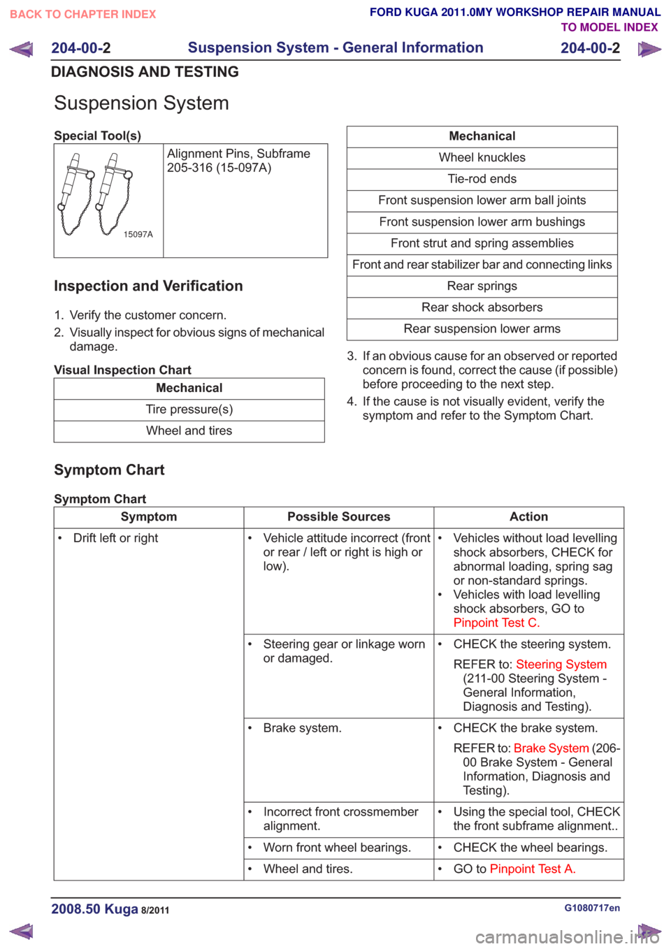
Suspension System
Special Tool(s)Alignment Pins, Subframe
205-316 (15-097A)
15097A
Inspection and Verification
1. Verify the customer concern.
2. Visually inspect for obvious signs of mechanicaldamage.
Visual Inspection Chart
Mechanical
Tire pressure(s) Wheel and tires
Mechanical
Wheel knuckles Tie-rod ends
Front suspension lower arm ball joints Front suspension lower arm bushings Front strut and spring assemblies
Front and rear stabilizer bar and connecting links Rear springs
Rear shock absorbers
Rear suspension lower arms
3. If an obvious cause for an observed or reported concern is found, correct the cause (if possible)
before proceeding to the next step.
4. If the cause is not visually evident, verify the symptom and refer to the Symptom Chart.
Symptom Chart
Symptom Chart
Action
Possible Sources
Symptom
• Vehicles without load levellingshock absorbers, CHECK for
abnormal loading, spring sag
or non-standard springs.
• Vehicles with load levelling shock absorbers, GO to
Pinpoint Test C.
• Vehicle attitude incorrect (front
or rear / left or right is high or
low).
• Drift left or right
• CHECK the steering system.REFER to: Steering System
(211-00 Steering System -
General Information,
Diagnosis and Testing).
• Steering gear or linkage worn
or damaged.
• CHECK the brake system.REFER to: Brake System (206-
00 Brake System - General
Information, Diagnosis and
Testing).
• Brake system.
• Using the special tool, CHECKthe front subframe alignment..
• Incorrect front crossmember
alignment.
• CHECK the wheel bearings.
• Worn front wheel bearings.
• GO toPinpoint Test A.
• Wheel and tires.
G1080717en2008.50 Kuga8/2011
204-00- 2
Suspension System - General Information
204-00- 2
DIAGNOSIS AND TESTING
TO MODEL INDEX
BACK TO CHAPTER INDEX
FORD KUGA 2011.0MY WORKSHOP REPAIR MANUAL
Page 187 of 2057
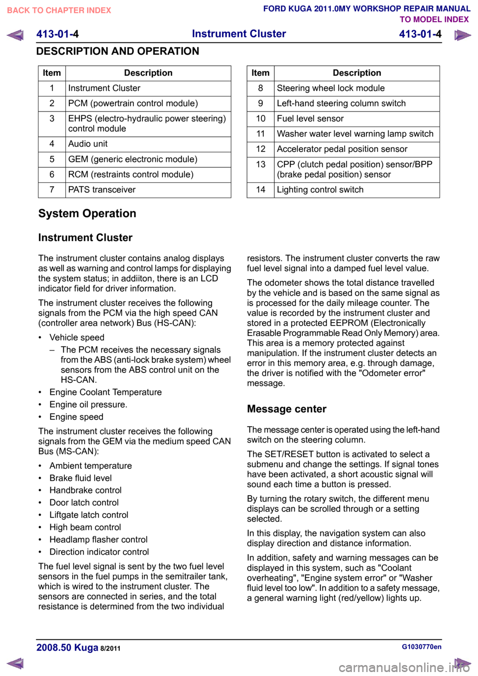
Description
Item
Instrument Cluster
1
PCM (powertrain control module)
2
EHPS (electro-hydraulic power steering)
control module
3
Audio unit
4
GEM (generic electronic module)
5
RCM (restraints control module)
6
PATS transceiver
7 Description
Item
Steering wheel lock module
8
Left-hand steering column switch
9
Fuel level sensor
10
Washer water level warning lamp switch
11
Accelerator pedal position sensor
12
CPP (clutch pedal position) sensor/BPP
(brake pedal position) sensor
13
Lighting control switch
14
System Operation
Instrument Cluster
The instrument cluster contains analog displays
as well as warning and control lamps for displaying
the system status; in addiiton, there is an LCD
indicator field for driver information.
The instrument cluster receives the following
signals from the PCM via the high speed CAN
(controller area network) Bus (HS-CAN):
• Vehicle speed – The PCM receives the necessary signalsfrom the ABS (anti-lock brake system) wheel
sensors from the ABS control unit on the
HS-CAN.
• Engine Coolant Temperature
• Engine oil pressure.
• Engine speed
The instrument cluster receives the following
signals from the GEM via the medium speed CAN
Bus (MS-CAN):
• Ambient temperature
• Brake fluid level
• Handbrake control
• Door latch control
• Liftgate latch control
• High beam control
• Headlamp flasher control
• Direction indicator control
The fuel level signal is sent by the two fuel level
sensors in the fuel pumps in the semitrailer tank,
which is wired to the instrument cluster. The
sensors are connected in series, and the total
resistance is determined from the two individual resistors. The instrument cluster converts the raw
fuel level signal into a damped fuel level value.
The odometer shows the total distance travelled
by the vehicle and is based on the same signal as
is processed for the daily mileage counter. The
value is recorded by the instrument cluster and
stored in a protected EEPROM (Electronically
Erasable Programmable Read Only Memory) area.
This area is a memory protected against
manipulation. If the instrument cluster detects an
error in this memory area, e.g. through damage,
the driver is notified with the "Odometer error"
message.
Message center
The message center is operated using the left-hand
switch on the steering column.
The SET/RESET button is activated to select a
submenu and change the settings. If signal tones
have been activated, a short acoustic signal will
sound each time a button is pressed.
By turning the rotary switch, the different menu
displays can be scrolled through or a setting
selected.
In this display, the navigation system can also
display direction and distance information.
In addition, safety and warning messages can be
displayed in this system, such as "Coolant
overheating", "Engine system error" or "Washer
fluid level too low". In addition to a safety message,
a general warning light (red/yellow) lights up.
G1030770en
2008.50 Kuga 8/2011 413-01-4
Instrument Cluster
413-01-4
DESCRIPTION AND OPERATIONTO MODEL INDEX
BACK TO CHAPTER INDEX
FORD KUGA 2011.0MY WORKSHOP REPAIR MANUAL
Page 190 of 2057
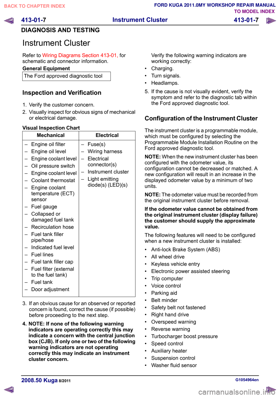
Instrument Cluster
Refer to
Wiring Diagrams Section 413-01, for
schematic and connector information. General Equipment
The Ford approved diagnostic tool
Inspection and Verification
1. Verify the customer concern.
2. Visually inspect for obvious signs of mechanical
or electrical damage.
Visual Inspection Chart Electrical
Mechanical
– Fuse(s)
– Wiring harness
– Electricalconnector(s)
– Instrument cluster
– Light emitting diode(s) (LED)(s)
– Engine oil filter
– Engine oil level
–
Engine coolant level
– Oil pressure switch
– Engine coolant level
– Coolant thermostat
– Engine coolant temperature (ECT)
sensor
– Fuel gauge
– Collapsed or damaged fuel tank
– Recirculation hose
– Fuel tank filler pipe/hose
– Indicated fuel level
– Fuel lines
– Fuel tank filler cap
– Fuel filter (external to the fuel tank)
– Fuel tank
– Door adjustment
3. If an obvious cause for an observed or reported concern is found, correct the cause (if possible)
before proceeding to the next step.
4. NOTE: If none of the following warning indicators are operating correctly this may
indicate a concern with the central junction
box (CJB). If only one or two of the following
warning indicators are not operating
correctly this may indicate an instrument
cluster concern. Verify the following warning indicators are
working correctly:
• Charging.
• Turn signals.
• Headlamps.
5. If the cause is not visually evident, verify the symptom and refer to the diagnostic tab within
the Ford approved diagnostic tool.
Configuration of the Instrument Cluster
The instrument cluster is a programmable module,
which must be configured by selecting the
Programmable Module Installation Routine on the
Ford approved diagnostic tool.
NOTE: When the new instrument cluster has been
configured with the odometer value, its
configuration cannot be decreased or matched. A
new configuration will result in an increase in the
displayed odometer value by a minimum of two
units.
NOTE: The odometer value must be recorded from
the original instrument cluster before removal.
If the odometer value cannot be obtained from
the original instrument cluster (display failure)
the customer should supply the approximate
value.
The following features will need to be configured
when a new instrument cluster is installed:
• Anti-lock Brake System (ABS)
• All wheel drive
• Keyless vehicle entry
• Electronic power assisted steering
• Trip computer
• Voice control
• Parking aid
• Belt minder
• Safety belt not fastened
• Right hand drive
• Overspeed warning
• Reverse warning
• Turbocharger boost pressure
• Speed control
• Auxiliary heater
• Suspension control
• Washer fluid sensor G1054964en
2008.50 Kuga 8/2011 413-01-7
Instrument Cluster
413-01-7
DIAGNOSIS AND TESTINGTO MODEL INDEX
BACK TO CHAPTER INDEX
FORD KUGA 2011.0MY WORKSHOP REPAIR MANUAL
Page 195 of 2057
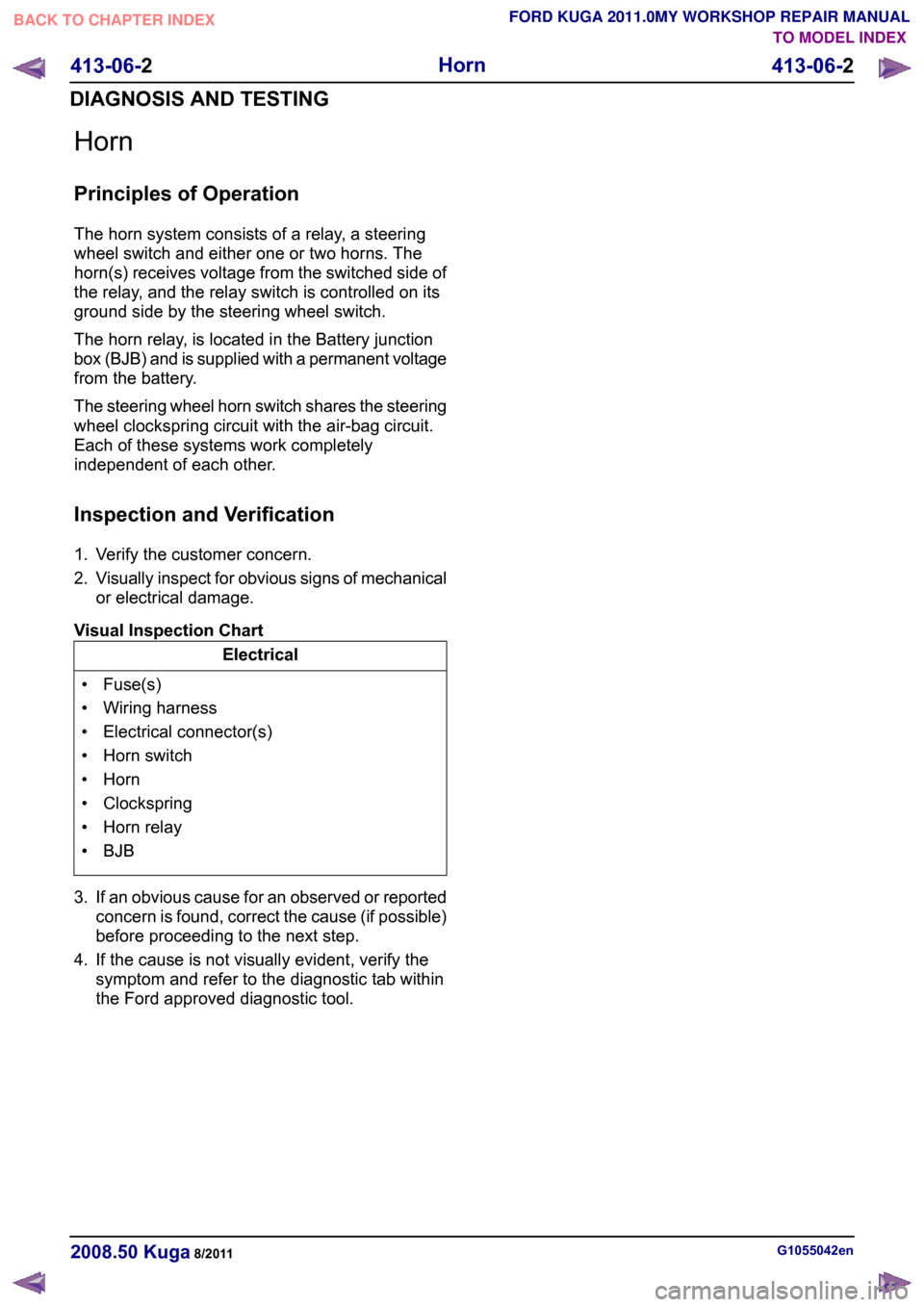
Horn
Principles of Operation
The horn system consists of a relay, a steering
wheel switch and either one or two horns. The
horn(s) receives voltage from the switched side of
the relay, and the relay switch is controlled on its
ground side by the steering wheel switch.
The horn relay, is located in the Battery junction
box (BJB) and is supplied with a permanent voltage
from the battery.
The steering wheel horn switch shares the steering
wheel clockspring circuit with the air-bag circuit.
Each of these systems work completely
independent of each other.
Inspection and Verification
1. Verify the customer concern.
2.
Visually inspect for obvious signs of mechanical
or electrical damage.
Visual Inspection Chart Electrical
• Fuse(s)
• Wiring harness
• Electrical connector(s)
• Horn switch
• Horn
• Clockspring
• Horn relay
• BJB
3. If an obvious cause for an observed or reported concern is found, correct the cause (if possible)
before proceeding to the next step.
4. If the cause is not visually evident, verify the symptom and refer to the diagnostic tab within
the Ford approved diagnostic tool. G1055042en
2008.50 Kuga 8/2011 413-06-2
Horn
413-06-2
DIAGNOSIS AND TESTINGTO MODEL INDEX
BACK TO CHAPTER INDEX
FORD KUGA 2011.0MY WORKSHOP REPAIR MANUAL