fluid FORD KUGA 2011 1.G Workshop Manual
[x] Cancel search | Manufacturer: FORD, Model Year: 2011, Model line: KUGA, Model: FORD KUGA 2011 1.GPages: 2057
Page 1980 of 2057
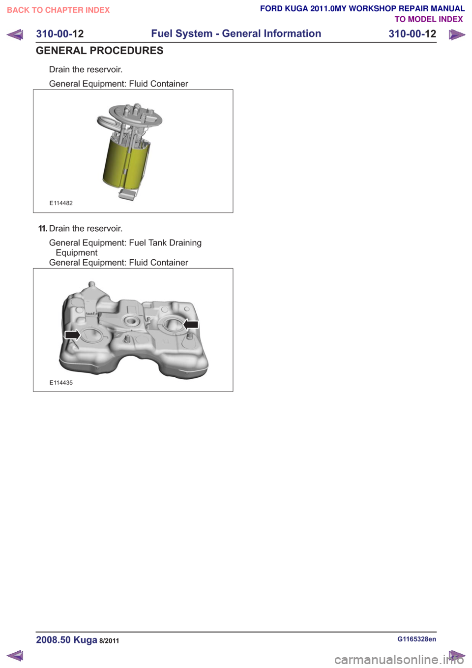
Drain the reservoir.
General Equipment: Fluid Container
E114482
11 .Drain the reservoir.
General Equipment: Fuel Tank Draining
Equipment
General Equipment: Fluid Container
E114435
G1165328en2008.50 Kuga8/2011
310-00- 12
Fuel System - General Information
310-00- 12
GENERAL PROCEDURES
TO MODEL INDEX
BACK TO CHAPTER INDEX
FORD KUGA 2011.0MY WORKSHOP REPAIR MANUAL
Page 1989 of 2057
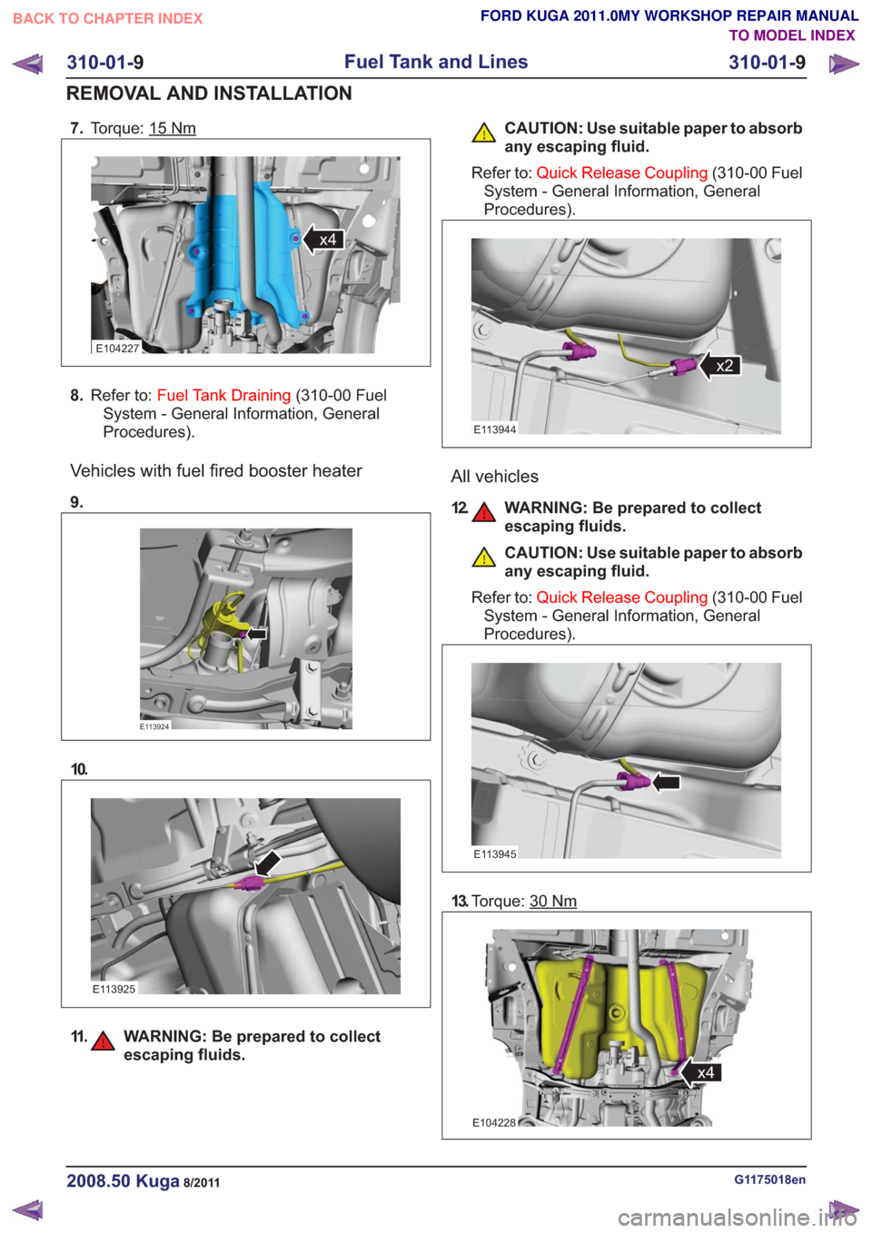
7.Torque: 15Nm
x4x4
E104227
8.Refer to: Fuel Tank Draining (310-00 Fuel
System - General Information, General
Procedures).
Vehicles with fuel fired booster heater
9.
E113924
10.
E113925
11. WARNING: Be prepared to collect escaping fluids.
CAUTION: Use suitable paper to absorb
any escaping fluid.
Refer to: Quick Release Coupling (310-00 Fuel
System - General Information, General
Procedures).
x2x2
E113944
All vehicles
12. WARNING: Be prepared to collect escaping fluids.
CAUTION: Use suitable paper to absorb
any escaping fluid.
Refer to: Quick Release Coupling (310-00 Fuel
System - General Information, General
Procedures).
E113945
13. Torque: 30Nm
x4x4
E104228
G1175018en2008.50 Kuga8/2011
310-01- 9
Fuel Tank and Lines
310-01- 9
REMOVAL AND INSTALLATION
TO MODEL INDEX
BACK TO CHAPTER INDEX
FORD KUGA 2011.0MY WORKSHOP REPAIR MANUAL
Page 1990 of 2057
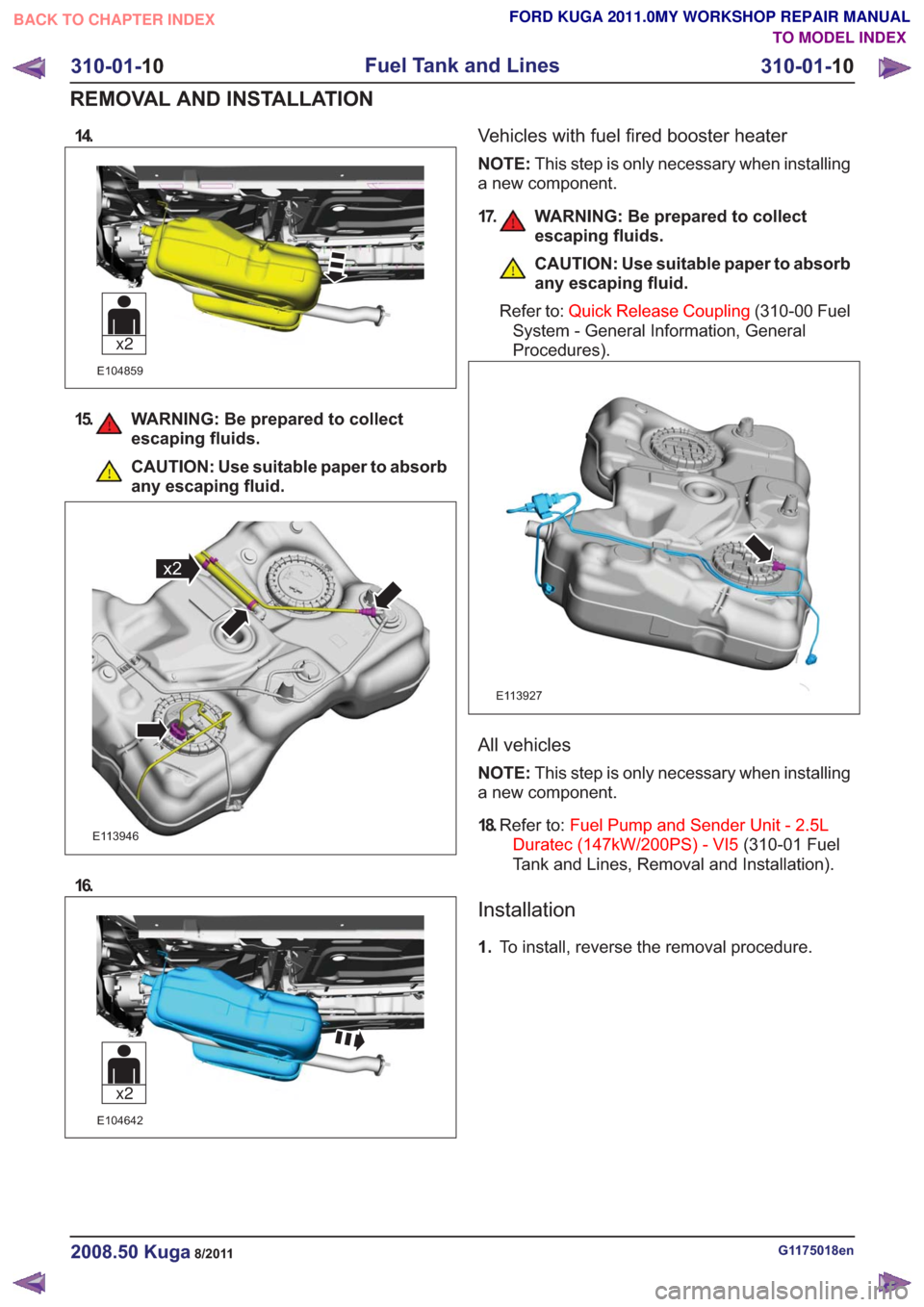
14.
E104859
x2
15. WARNING: Be prepared to collectescaping fluids.
CAUTION: Use suitable paper to absorb
any escaping fluid.
x2x2
E113946
16.
E104642
x2
Vehicles with fuel fired booster heater
NOTE:This step is only necessary when installing
a new component.
17. WARNING: Be prepared to collect escaping fluids.
CAUTION: Use suitable paper to absorb
any escaping fluid.
Refer to: Quick Release Coupling (310-00 Fuel
System - General Information, General
Procedures).
E113927
All vehicles
NOTE: This step is only necessary when installing
a new component.
18. Refer to: Fuel Pump and Sender Unit - 2.5L
Duratec (147kW/200PS) - VI5 (310-01 Fuel
Tank and Lines, Removal and Installation).
Installation
1. To install, reverse the removal procedure.
G1175018en2008.50 Kuga8/2011
310-01- 10
Fuel Tank and Lines
310-01- 10
REMOVAL AND INSTALLATION
TO MODEL INDEX
BACK TO CHAPTER INDEX
FORD KUGA 2011.0MY WORKSHOP REPAIR MANUAL
Page 1992 of 2057
Fuel Tank Filler Pipe
General EquipmentFluid ContainerGeneral EquipmentFuel Tank Draining Equipment
Hose Clamp Remover/Installer
Removal
WARNING: Make sure that the fuel tank is
no more than 3/4 full.
NOTE: Removal steps in this procedure may
contain installation details.
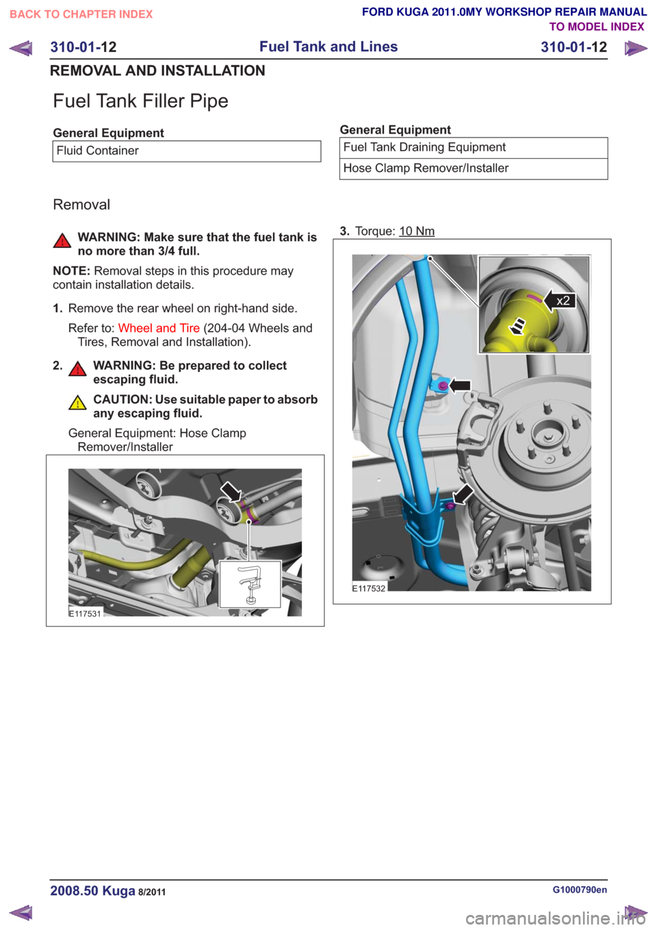
1. Remove the rear wheel on right-hand side.
Refer to: Wheel and Tire (204-04 Wheels and
Tires, Removal and Installation).
2. WARNING: Be prepared to collect escaping fluid.
CAUTION: Use suitable paper to absorb
any escaping fluid.
General Equipment: Hose Clamp Remover/Installer
E117531
3. Torque: 10Nm
x2x2
E117532
G1000790en2008.50 Kuga8/2011
310-01- 12
Fuel Tank and Lines
310-01- 12
REMOVAL AND INSTALLATION
TO MODEL INDEX
BACK TO CHAPTER INDEX
FORD KUGA 2011.0MY WORKSHOP REPAIR MANUAL
Page 1993 of 2057
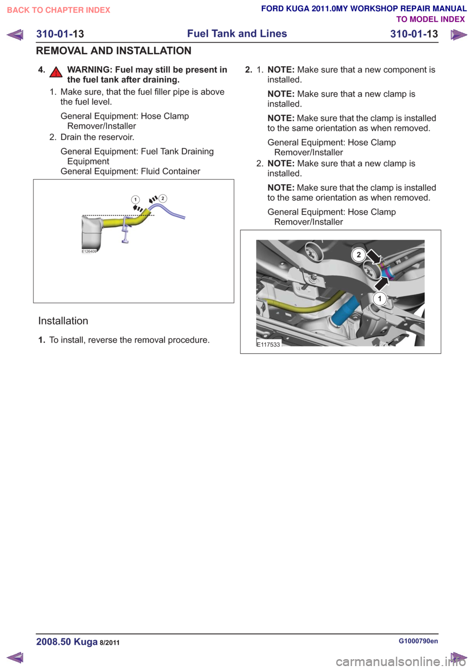
4. WARNING: Fuel may still be present inthe fuel tank after draining.
1. Make sure, that the fuel filler pipe is abovethe fuel level.
General Equipment: Hose ClampRemover/Installer
2. Drain the reservoir.
General Equipment: Fuel Tank DrainingEquipment
General Equipment: Fluid Container
E126409
12
Installation
1. To install, reverse the removal procedure. 2. NOTE:
Make sure that a new component is
installed.
1.
NOTE: Make sure that a new clamp is
installed.
NOTE: Make sure that the clamp is installed
to the same orientation as when removed.
General Equipment: Hose Clamp Remover/Installer
2. NOTE: Make sure that a new clamp is
installed.
NOTE: Make sure that the clamp is installed
to the same orientation as when removed.
General Equipment: Hose Clamp Remover/Installer
1
2
E117533
G1000790en2008.50 Kuga8/2011
310-01- 13
Fuel Tank and Lines
310-01- 13
REMOVAL AND INSTALLATION
TO MODEL INDEX
BACK TO CHAPTER INDEX
FORD KUGA 2011.0MY WORKSHOP REPAIR MANUAL
Page 1998 of 2057
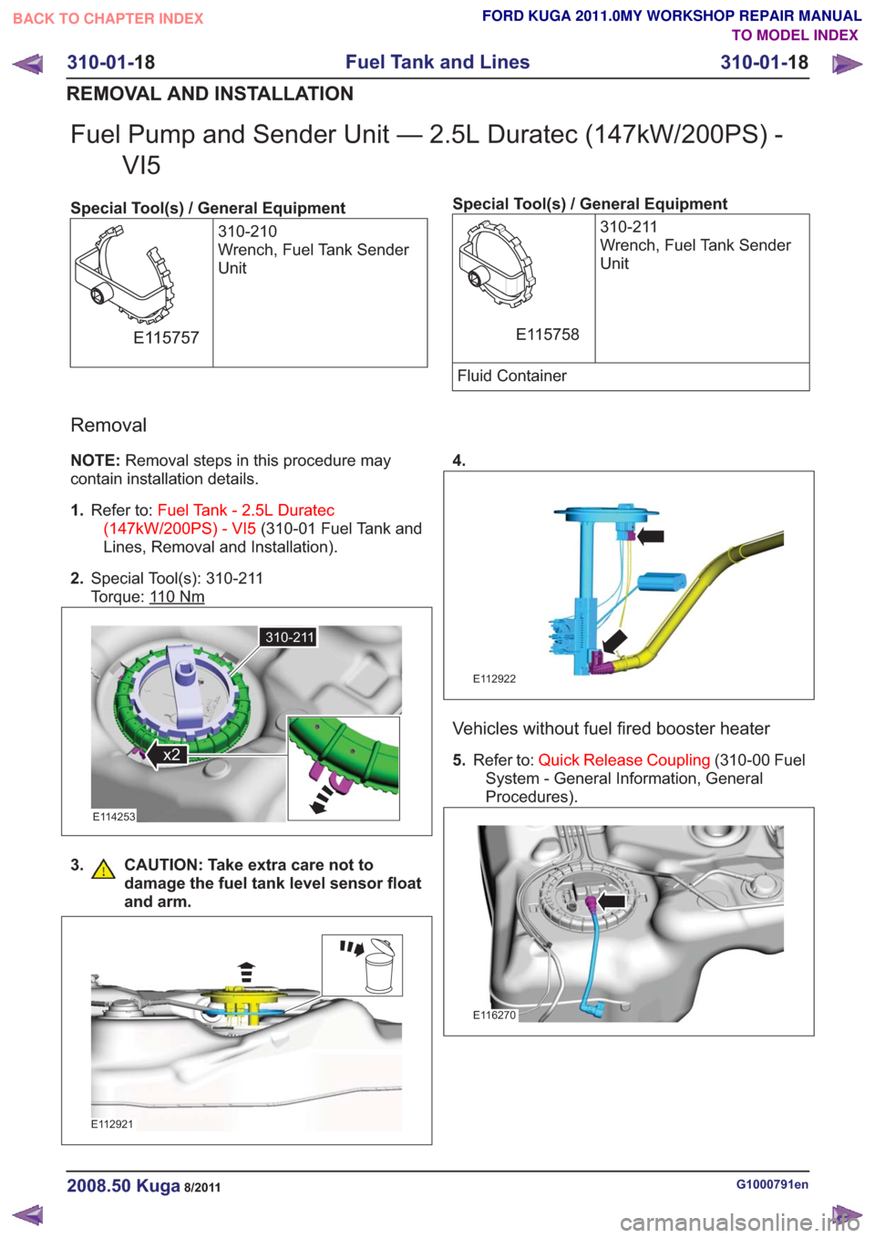
Fuel Pump and Sender Unit — 2.5L Duratec (147kW/200PS) -VI5
Special Tool(s) / General Equipment
310-210
Wrench, Fuel Tank Sender
Unit
E115757
Special Tool(s) / General Equipment310-211
Wrench, Fuel Tank Sender
Unit
E115758
Fluid Container
Removal
NOTE:Removal steps in this procedure may
contain installation details.
1. Refer to: Fuel Tank - 2.5L Duratec
(147kW/200PS) - VI5 (310-01 Fuel Tank and
Lines, Removal and Installation).
2. Special Tool(s): 310-211
Torque: 1
10Nm
310-211
x2
310-211
x2
E114253
3. CAUTION: Take extra care not to
damage the fuel tank level sensor float
and arm.
E112921
4.
E112922
Vehicles without fuel fired booster heater
5.Refer to: Quick Release Coupling (310-00 Fuel
System - General Information, General
Procedures).
E116270
G1000791en2008.50 Kuga8/2011
310-01- 18
Fuel Tank and Lines
310-01- 18
REMOVAL AND INSTALLATION
TO MODEL INDEX
BACK TO CHAPTER INDEX
FORD KUGA 2011.0MY WORKSHOP REPAIR MANUAL
Page 1999 of 2057
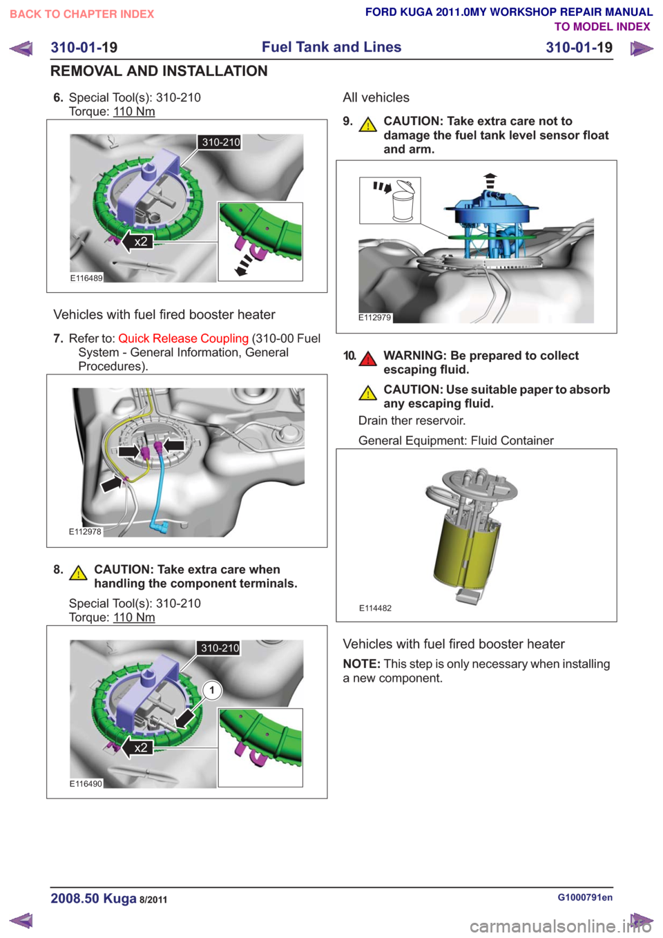
6.Special Tool(s): 310-210
Torque: 1
10Nm
310-210
x2
310-210
x2
E116489
Vehicles with fuel fired booster heater
7.Refer to: Quick Release Coupling (310-00 Fuel
System - General Information, General
Procedures).
E112978
8. CAUTION: Take extra care when handling the component terminals.
Special Tool(s): 310-210
Torque: 1
10Nm
310-210
x2
310-210
x2
E116490
1
All vehicles
9. CAUTION: Take extra care not todamage the fuel tank level sensor float
and arm.
E112979
10. WARNING: Be prepared to collectescaping fluid.
CAUTION: Use suitable paper to absorb
any escaping fluid.
Drain ther reservoir.
General Equipment: Fluid Container
E114482
Vehicles with fuel fired booster heater
NOTE: This step is only necessary when installing
a new component.
G1000791en2008.50 Kuga8/2011
310-01- 19
Fuel Tank and Lines
310-01- 19
REMOVAL AND INSTALLATION
TO MODEL INDEX
BACK TO CHAPTER INDEX
FORD KUGA 2011.0MY WORKSHOP REPAIR MANUAL
Page 2013 of 2057
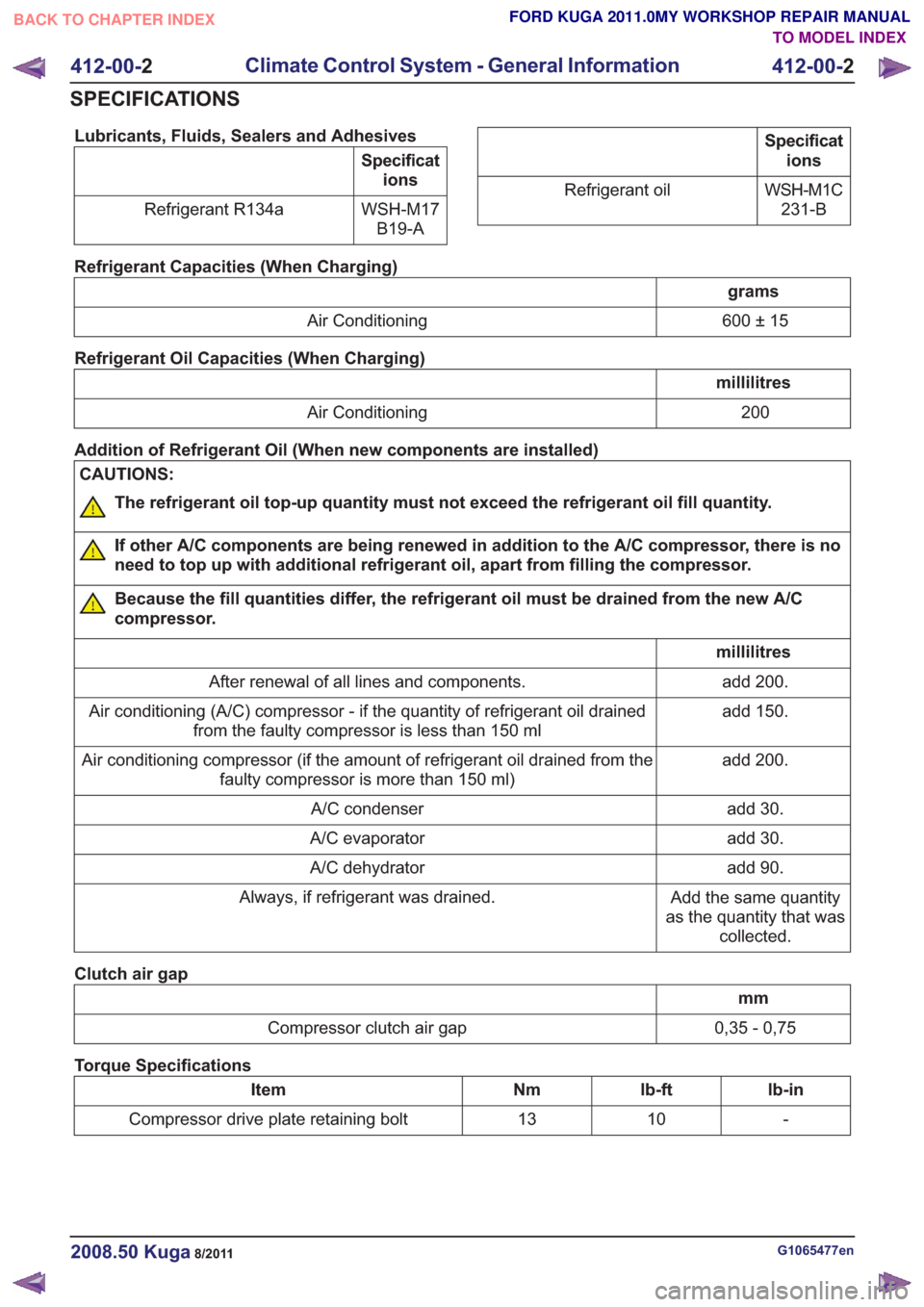
Lubricants, Fluids, Sealers and Adhesives
Specifications
WSH-M17 B19-A
Refrigerant R134a
Specificat
ions
WSH-M1C 231-B
Refrigerant oil
Refrigerant Capacities (When Charging)
grams
600 ± 15
Air Conditioning
Refrigerant Oil Capacities (When Charging)
millilitres 200
Air Conditioning
Addition of Refrigerant Oil (When new components are installed)
CAUTIONS:
The refrigerant oil top-up quantity must not exceed the refrigerant oil fill quantity.
If other A/C components are being renewed in addition to the A/C compressor, there is no
need to top up with additional refrigerant oil, apart from filling the compressor.
Because the fill quantities differ, the refrigerant oil must be drained from the new A/C
compressor.
millilitres add 200.
After renewal of all lines and components.
add 150.
Air conditioning (A/C) compressor - if the quantity of refrigerant oil drained
from the faulty compressor is less than 150 ml
add 200.
Air conditioning compressor (if the amount of refrigerant oil drained from the
faulty compressor is more than 150 ml)
add 30.
A/C condenser
add 30.
A/C evaporator
add 90.
A/C dehydrator
Add the same quantity
as the quantity that was collected.
Always, if refrigerant was drained.
Clutch air gap
mm
0,35 - 0,75
Compressor clutch air gap
Torque Specifications
lb-in
lb-ft
Nm
Item
-
10
13
Compressor drive plate retaining bolt
G1065477en2008.50 Kuga8/2011
412-00- 2
Climate Control System - General Information
412-00- 2
SPECIFICATIONS
TO MODEL INDEX
BACK TO CHAPTER INDEX
FORD KUGA 2011.0MY WORKSHOP REPAIR MANUAL