gear selector FORD KUGA 2011 1.G Owner's Manual
[x] Cancel search | Manufacturer: FORD, Model Year: 2011, Model line: KUGA, Model: FORD KUGA 2011 1.GPages: 2057
Page 1882 of 2057
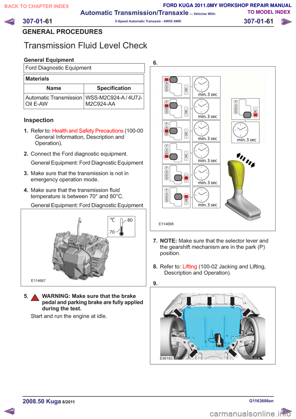
Transmission Fluid Level Check
General EquipmentFord Diagnostic Equipment
Materials
Specification
Name
WSS-M2C924-A / 4U7J-
M2C924-AA
Automatic Transmission
Oil E-AW
Inspection
1.
Refer to: Health and Safety Precautions (100-00
General Information, Description and
Operation).
2. Connect the Ford diagnostic equipment.
General Equipment: Ford Diagnostic Equipment
3. Make sure that the transmission is not in
emergency operation mode.
4. Make sure that the transmission fluid
temperature is between 70° and 80°C.
General Equipment: Ford Diagnostic Equipment
80
70
E114667
5. WARNING: Make sure that the brake pedal and parking brake are fully applied
during the test.
Start and run the engine at idle. 6.
E114668
7. NOTE:
Make sure that the selector lever and
the gearshift mechanism are in the park (P)
position.
8. Refer to: Lifting(100-02 Jacking and Lifting,
Description and Operation).
9.
E98183
G1163606en2008.50 Kuga8/2011
307-01- 61
Automatic Transmission/Transaxle
— Vehicles With:
5-Speed Automatic Transaxle - AW55 AWD
307-01- 61
GENERAL PROCEDURES
TO MODEL INDEX
BACK TO CHAPTER INDEX
FORD KUGA 2011.0MY WORKSHOP REPAIR MANUAL
Page 1885 of 2057
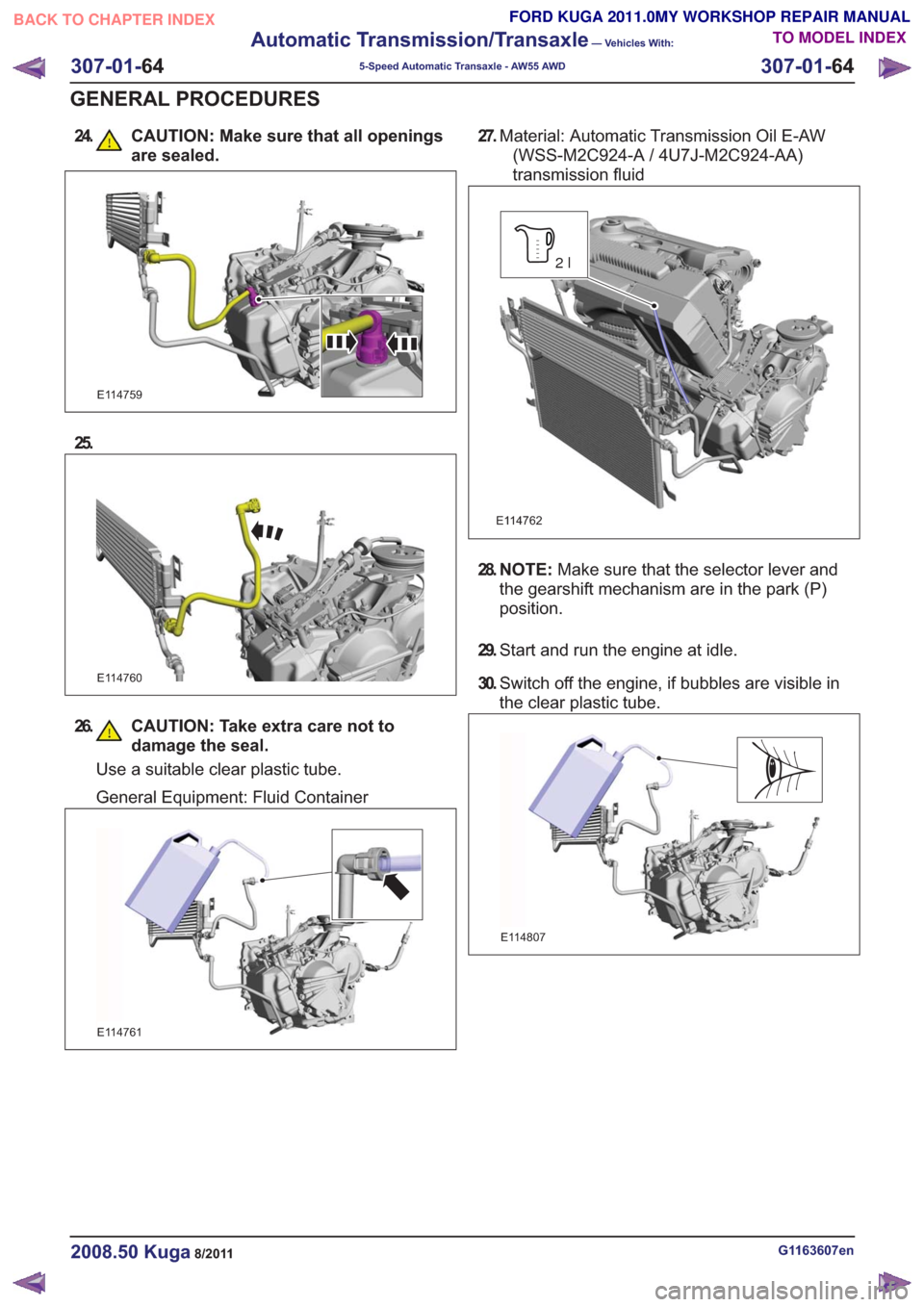
24. CAUTION: Make sure that all openingsare sealed.
E114759
25.
E114760
26. CAUTION: Take extra care not todamage the seal.
Use a suitable clear plastic tube.
General Equipment: Fluid Container
E114761
27.Material: Automatic Transmission Oil E-AW
(WSS-M2C924-A / 4U7J-M2C924-AA)
transmission fluid
E114762
2l
28. N O T E : Make sure that the selector lever and
the gearshift mechanism are in the park (P)
position.
29. Start and run the engine at idle.
30. Switch off the engine, if bubbles are visible in
the clear plastic tube.
E114807
G1163607en2008.50 Kuga8/2011
307-01- 64
Automatic Transmission/Transaxle
— Vehicles With:
5-Speed Automatic Transaxle - AW55 AWD
307-01- 64
GENERAL PROCEDURES
TO MODEL INDEX
BACK TO CHAPTER INDEX
FORD KUGA 2011.0MY WORKSHOP REPAIR MANUAL
Page 1934 of 2057
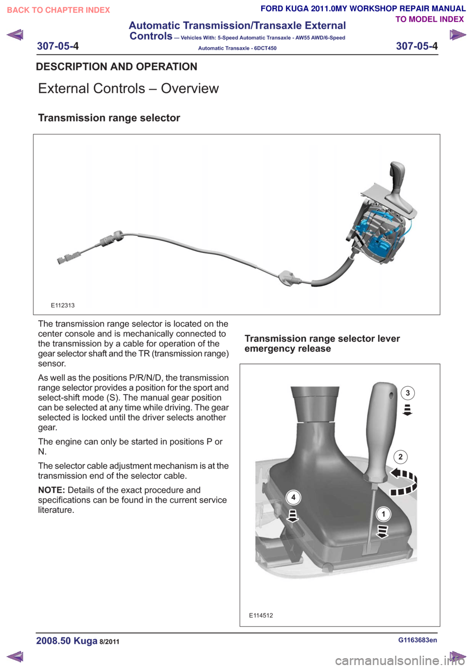
External Controls – Overview
Transmission range selector
E112313
The transmission range selector is located on the
center console and is mechanically connected to
the transmission by a cable for operation of the
gear selector shaft and the TR (transmission range)
sensor.
As well as the positions P/R/N/D, the transmission
range selector provides a position for the sport and
select-shift mode (S). The manual gear position
can be selected at any time while driving. The gear
selected is locked until the driver selects another
gear.
The engine can only be started in positions P or
N.
The selector cable adjustment mechanism is at the
transmission end of the selector cable.
NOTE:Details of the exact procedure and
specifications can be found in the current service
literature.
Transmission range selector lever
emergency release
E114512
1
2
3
4
G1163683en2008.50 Kuga8/2011
DESCRIPTION AND OPERATION
TO MODEL INDEX
BACK TO CHAPTER INDEX
FORD KUGA 2011.0MY WORKSHOP REPAIR MANUAL
307-05-
4
Automatic Transmission/Transaxle External
Controls
— Vehicles With: 5-Speed Automatic Transaxle - AW55 AWD/6-Speed
Automatic Transaxle - 6DCT450
307-05-4
.
Page 1936 of 2057
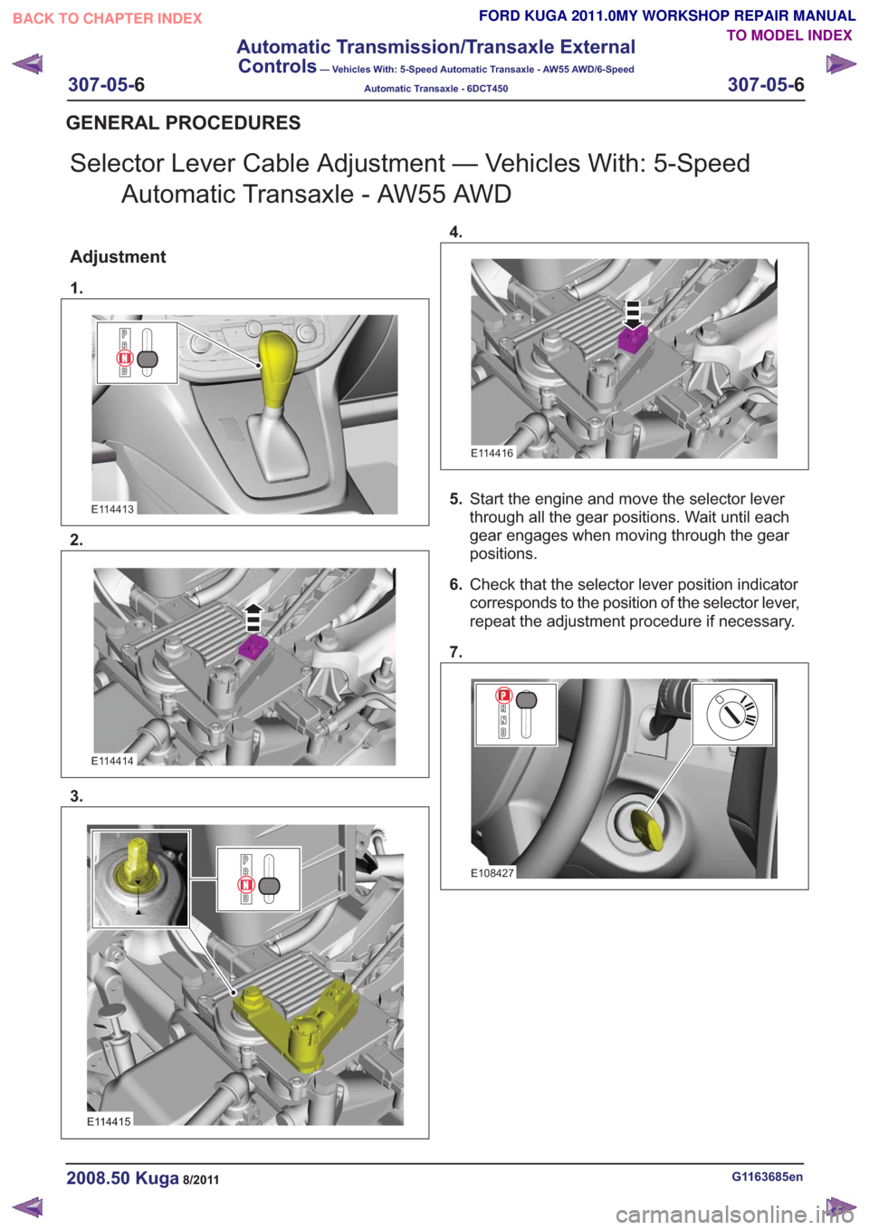
Selector Lever Cable Adjustment — Vehicles With: 5-SpeedAutomatic Transaxle - AW55 AWD
Adjustment
1.
E114413
2.
E114414
3.
E114415
4.
E114416
5.Start the engine and move the selector lever
through all the gear positions. Wait until each
gear engages when moving through the gear
positions.
6. Check that the selector lever position indicator
corresponds to the position of the selector lever,
repeat the adjustment procedure if necessary.
7.
E108427
G1163685en2008.50 Kuga8/2011
GENERAL PROCEDURES
TO MODEL INDEX
BACK TO CHAPTER INDEX
FORD KUGA 2011.0MY WORKSHOP REPAIR MANUAL
307-05-
6
Automatic Transmission/Transaxle External
Controls
— Vehicles With: 5-Speed Automatic Transaxle - AW55 AWD/6-Speed
Automatic Transaxle - 6DCT450
307-05-6
.
Page 1940 of 2057
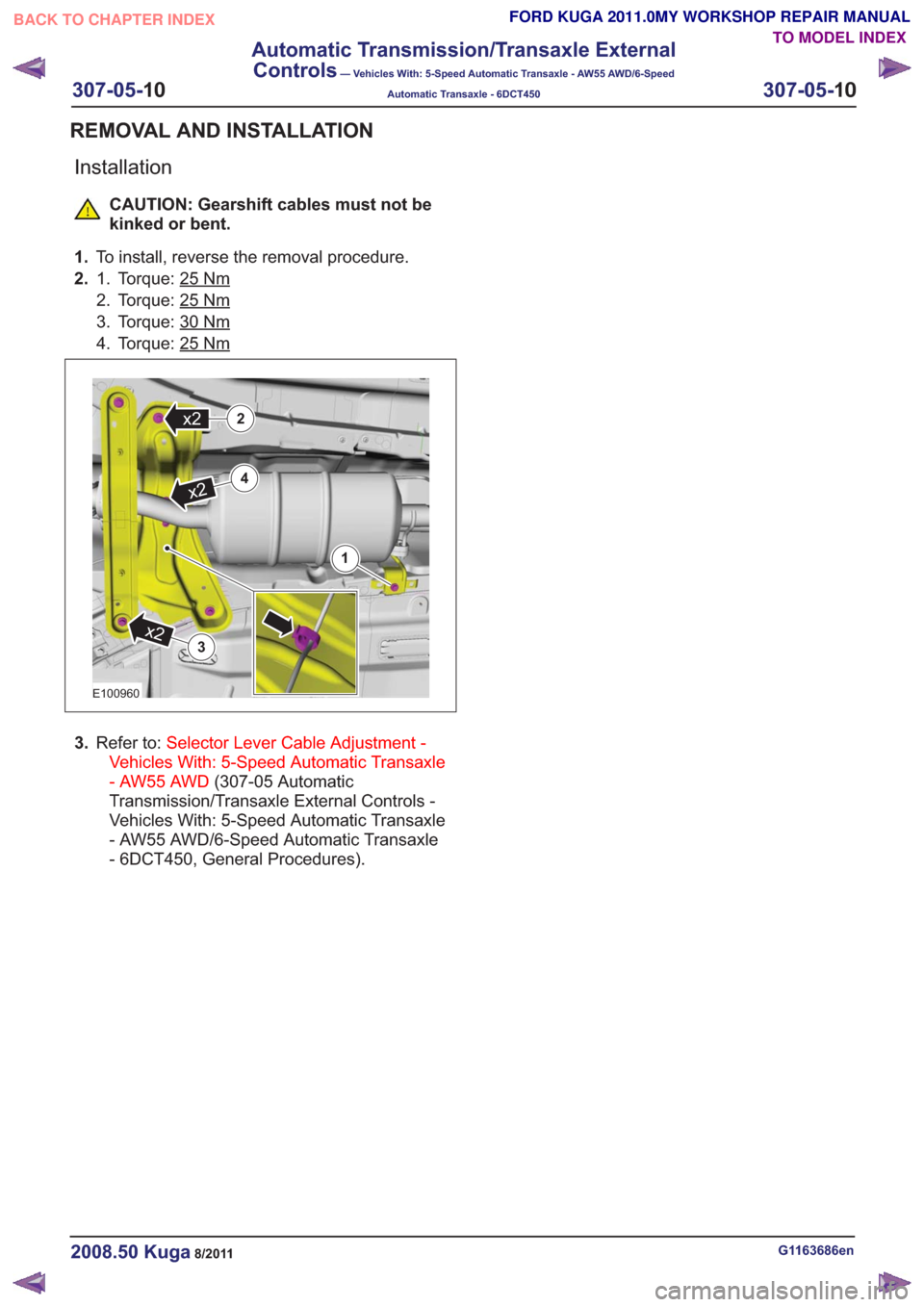
Installation
CAUTION: Gearshift cables must not be
kinked or bent.
1. To install, reverse the removal procedure.
2. Torque: 25
Nm1.
2. Torque: 25
Nm
3. Torque: 30Nm
4. Torque: 25Nm
4
x2
2x2
1
3
x2
4
x2
2x2
1
3
x2
E100960
Vehicles With: 5-Speed Automatic Transaxle
- AW55 AWD (307-05 Automatic
Transmission/Transaxle External Controls -
Vehicles With: 5-Speed Automatic Transaxle
- AW55 AWD/6-Speed Automatic Transaxle
- 6DCT450, General Procedures).
G1163686en2008.50 Kuga8/2011
REMOVAL AND INSTALLATION
TO MODEL INDEX
BACK TO CHAPTER INDEX
3.
Refer to: Selector Lever Cable Adjustment -
FORD KUGA 2011.0MY WORKSHOP REPAIR MANUAL
307-05-10
Automatic Transmission/Transaxle External
Controls
— Vehicles With: 5-Speed Automatic Transaxle - AW55 AWD/6-Speed
Automatic Transaxle - 6DCT450
307-05-10
.
Page 1941 of 2057
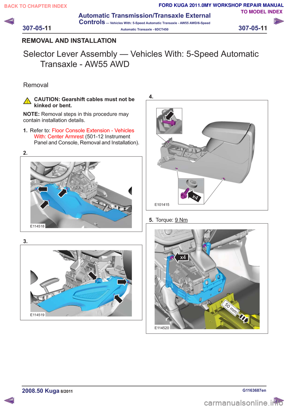
Selector Lever Assembly — Vehicles With: 5-Speed AutomaticTransaxle - AW55 AWD
Removal
CAUTION: Gearshift cables must not be
kinked or bent.
NOTE: Removal steps in this procedure may
contain installation details.
1. Refer to: Floor Console Extension - Vehicles
With: Center Armrest (501-12 Instrument
Panel and Console, Removal and Installation).
2.
E114518
3.
E114519
4.
x4x4
E101415
5. Torque: 9Nm
50 mm
x4
50 mm
x4
E114520
G1163687en2008.50 Kuga8/2011
REMOVAL AND INSTALLATION
TO MODEL INDEX
BACK TO CHAPTER INDEX
FORD KUGA 2011.0MY WORKSHOP REPAIR MANUAL
307-05-
11
Automatic Transmission/Transaxle External
Controls
— Vehicles With: 5-Speed Automatic Transaxle - AW55 AWD/6-Speed
Automatic Transaxle - 6DCT450
307-05-11
.
Page 1942 of 2057
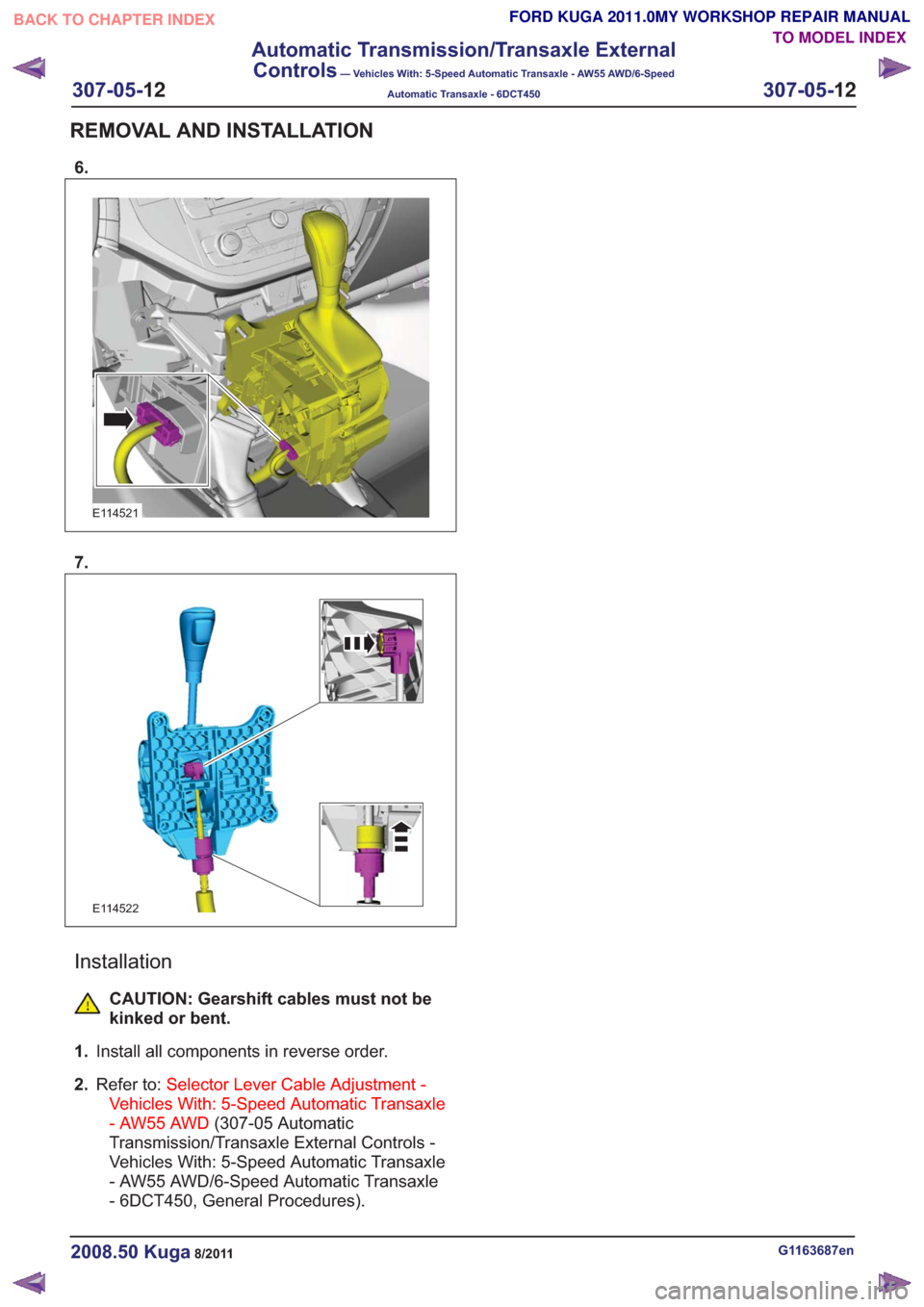
6.
E114521
7.
E114522
Installation
CAUTION: Gearshift cables must not be
kinked or bent.
1. Install all components in reverse order.
2. Refer to: Selector Lever Cable Adjustment -
Vehicles With: 5-Speed Automatic Transaxle
- AW55 AWD (307-05 Automatic
Transmission/Transaxle External Controls -
Vehicles With: 5-Speed Automatic Transaxle
- AW55 AWD/6-Speed Automatic Transaxle
- 6DCT450, General Procedures).
G1163687en2008.50 Kuga8/2011
REMOVAL AND INSTALLATION
TO MODEL INDEX
BACK TO CHAPTER INDEX
FORD KUGA 2011.0MY WORKSHOP REPAIR MANUAL
307-05-
12
Automatic Transmission/Transaxle External
Controls
— Vehicles With: 5-Speed Automatic Transaxle - AW55 AWD/6-Speed
Automatic Transaxle - 6DCT450
307-05-12
.
Page 2008 of 2057
control saves the current speed as the target
speed.
Cruise control goes into STANDBY mode in the
following situations:
• Operation of the brake pedal
• Operation of the clutch pedal
• Operation of the parking brake
• If the driver operates the accelerator pedal andthe saved target speed is subsequently
exceeded for more than 5 minutes.
• Pressing any cruise control button for more than 2 minutes
• Intervention by the traction control or electronic stability program (for longer than 40 ms)
• Shifting of the gear selector lever to the "N" position (vehicles with automatic transmission
only)
• Minimum speed falls below 40 km/h.
• Occurrence of particular DTC (diagnostic trouble code)
• faulty signal from the backup lamp switch
Cruise control is switched off when the "OFF"
button is pressed.
If the accelerator pedal is pressed down, the
vehicle speed increases. As soon as the pedal is
released, the speed falls to the saved target value. The following components supply the signals
needed by the cruise control:
• The APP sensor.
– The APP sensor identifies the currentposition of the accelerator pedal and sends
a PWM (pulse width modulation) signal to
the PCM and an analog DC (direct current)
signal to the GEM.
– If one or both of the APP sensors fails, a fault is stored in the PCM fault memory and cruise
control cannot be activated.
• BPP switch – The BPP switch tells the PCM whether thevehicle is being braked. In its rest state the
switch is closed and sends an earth signal
to the GEM. This signal is sent via the CAN
to the PCM.
– The brake light switch is likewise connected to the GEM and is opened in the rest state.
When the vehicle is braked, the brake light
switch sends a signal to the GEM. This
compares the signals from the BPP switch
and the brake light switch. If a discrepancy
occurs, a fault is stored in the error memory
of the GEM. Cruise control cannot be
activated.
• CPP switch – The CPP switch sends a ground signal to theGEM as soon as the clutch is operated. This
signal is passed on by the GEM via the CAN
bus to the PCM. This then supplies the signal
to the cruise control.
– If the CPP switch is incorrectly installed or set, cruise control cannot be activated.
• Wheel speed sensors – The wheel speed sensors record the speedof all the wheels. The recorded speed values
are sent to the ABS module via a hard-wired
connection. The ABS module calculates a
vehicle speed signal (VS signal) from the
speed values and the wheel diameter. This
vehicle speed signal is transferred via the
CAN bus to the PCM and supplied to the
cruise control. If the vehicle speed signal is
faulty, cruise control cannot be activated.
G1044191en2008.50 Kuga8/2011
310-03- 5
Speed Control
310-03- 5
DESCRIPTION AND OPERATION
TO MODEL INDEX
BACK TO CHAPTER INDEX
FORD KUGA 2011.0MY WORKSHOP REPAIR MANUAL