stop start FORD KUGA 2011 1.G Owner's Manual
[x] Cancel search | Manufacturer: FORD, Model Year: 2011, Model line: KUGA, Model: FORD KUGA 2011 1.GPages: 2057
Page 1865 of 2057

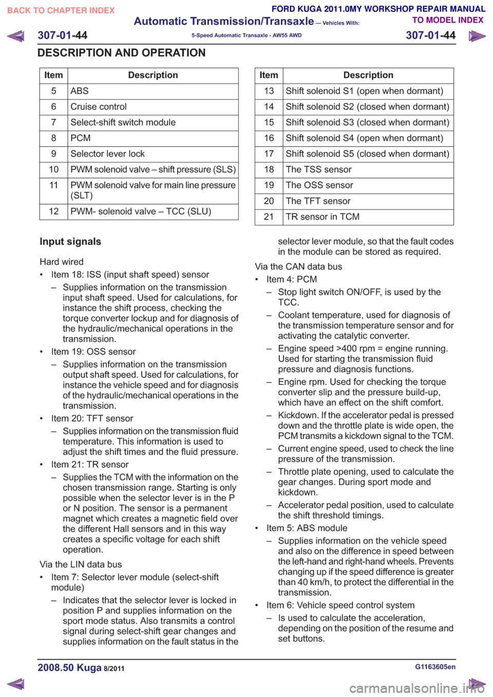
Description
Item
ABS5
Cruise control
6
Select-shift switch module
7
PCM
8
Selector lever lock
9
PWM solenoid valve – shift pressure (SLS)
10
PWM solenoid valve for main line pressure
(SLT)
11
PWM- solenoid valve – TCC (SLU)
12Description
Item
Shift solenoid S1 (open when dormant)
13
Shift solenoid S2 (closed when dormant)
14
Shift solenoid S3 (closed when dormant)
15
Shift solenoid S4 (open when dormant)
16
Shift solenoid S5 (closed when dormant)
17
The TSS sensor
18
The OSS sensor
19
The TFT sensor
20
TR sensor in TCM
21
Input signals
Hard wired
• Item 18: ISS (input shaft speed) sensor
– Supplies information on the transmissioninput shaft speed. Used for calculations, for
instance the shift process, checking the
torque converter lockup and for diagnosis of
the hydraulic/mechanical operations in the
transmission.
• Item 19: OSS sensor – Supplies information on the transmissionoutput shaft speed. Used for calculations, for
instance the vehicle speed and for diagnosis
of the hydraulic/mechanical operations in the
transmission.
• Item 20: TFT sensor – Supplies information on the transmission fluidtemperature. This information is used to
adjust the shift times and the fluid pressure.
• Item 21: TR sensor – Supplies the TCM with the information on thechosen transmission range. Starting is only
possible when the selector lever is in the P
or N position. The sensor is a permanent
magnet which creates a magnetic field over
the different Hall sensors and in this way
creates a specific voltage for each shift
operation.
Via the LIN data bus
• Item 7: Selector lever module (select-shift module)
– Indicates that the selector lever is locked inposition P and supplies information on the
sport mode status. Also transmits a control
signal during select-shift gear changes and
supplies information on the fault status in the selector lever module, so that the fault codes
in the module can be stored as required.
Via the CAN data bus
• Item 4: PCM – Stop light switch ON/OFF, is used by theTCC.
– Coolant temperature, used for diagnosis of the transmission temperature sensor and for
activating the catalytic converter.
– Engine speed >400 rpm = engine running. Used for starting the transmission fluid
pressure and diagnosis functions.
– Engine rpm. Used for checking the torque converter slip and the pressure build-up,
which have an effect on the shift comfort.
– Kickdown. If the accelerator pedal is pressed down and the throttle plate is wide open, the
PCM transmits a kickdown signal to the TCM.
– Current engine speed, used to check the line pressure of the transmission.
– Throttle plate opening, used to calculate the gear changes. During sport mode and
kickdown.
– Accelerator pedal position, used to calculate the shift threshold timings.
• Item 5: ABS module – Supplies information on the vehicle speedand also on the difference in speed between
the left-hand and right-hand wheels. Prevents
changing up if the speed difference is greater
than 40 km/h, to protect the differential in the
transmission.
• Item 6: Vehicle speed control system – Is used to calculate the acceleration,depending on the position of the resume and
set buttons.
G1163605en2008.50 Kuga8/2011
307-01- 44
Automatic Transmission/Transaxle
— Vehicles With:
5-Speed Automatic Transaxle - AW55 AWD
307-01- 44
DESCRIPTION AND OPERATION
TO MODEL INDEX
BACK TO CHAPTER INDEX
FORD KUGA 2011.0MY WORKSHOP REPAIR MANUAL