warning light FORD KUGA 2011 1.G Owner's Guide
[x] Cancel search | Manufacturer: FORD, Model Year: 2011, Model line: KUGA, Model: FORD KUGA 2011 1.GPages: 2057
Page 1527 of 2057
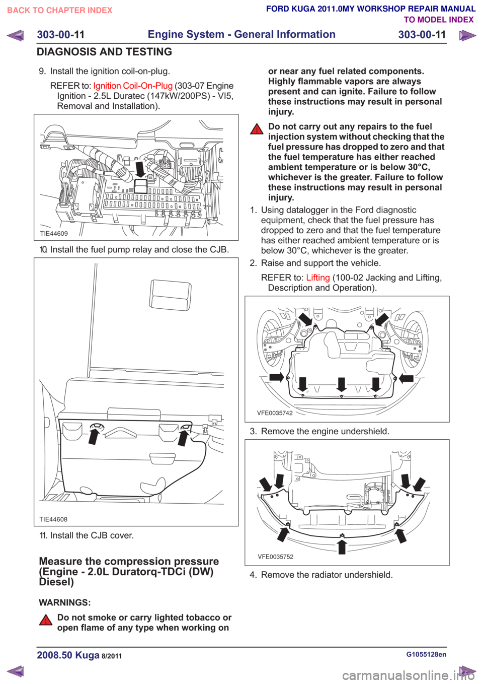
9. Install the ignition coil-on-plug.REFER to: Ignition Coil-On-Plug (303-07 Engine
Ignition - 2.5L Duratec (147kW/200PS) - VI5,
Removal and Installation).
TIE44609
10. Install the fuel pump relay and close the CJB.
TIE44608
11. Install the CJB cover.
Measure the compression pressure
(Engine - 2.0L Duratorq-TDCi (DW)
Diesel)
WARNINGS:
Do not smoke or carry lighted tobacco or
open flame of any type when working on or near any fuel related components.
Highly flammable vapors are always
present and can ignite. Failure to follow
these instructions may result in personal
injury.
Do not carry out any repairs to the fuel
injection system without checking that the
fuel pressure has dropped to zero and that
the fuel temperature has either reached
ambient temperature or is below 30°C,
whichever is the greater. Failure to follow
these instructions may result in personal
injury.
1. Using datalogger in the Ford diagnostic
equipment , check that the fuel pressure has
dropped to zero and that the fuel temperature
has either reached ambient temperature or is
below 30°C, whichever is the greater.
2. Raise and support the vehicle.
REFER to: Lifting(100-02 Jacking and Lifting,
Description and Operation).
VFE0035742
3. Remove the engine undershield.
VFE0035752
4. Remove the radiator undershield.
G1055128en2008.50 Kuga8/2011
303-00- 11
Engine System - General Information
303-00- 11
DIAGNOSIS AND TESTING
TO MODEL INDEX
BACK TO CHAPTER INDEX
FORD KUGA 2011.0MY WORKSHOP REPAIR MANUAL
Page 1792 of 2057
• Torque reduction request (stability assistmodule)
• Cruise control request
The PCM sends the following signals via the CAN
databus:
• Fuel pump relay on/off
• Engine speed
• Warning lights on/off (MIL (malfunction indicator lamp), battery warning lamp)
• PAT S
•ECT
• Air conditioning pressure transducer
• Outside air temperature
With the aid of the input and output signals listed
above, the PCM controls / regulates engine
starting, fuel injection and fuel pressure, ignition,
boost pressure, camshaft adjustment, tank purging,
the radiator fan and the refrigerant compressor.
Speed and TDC recording
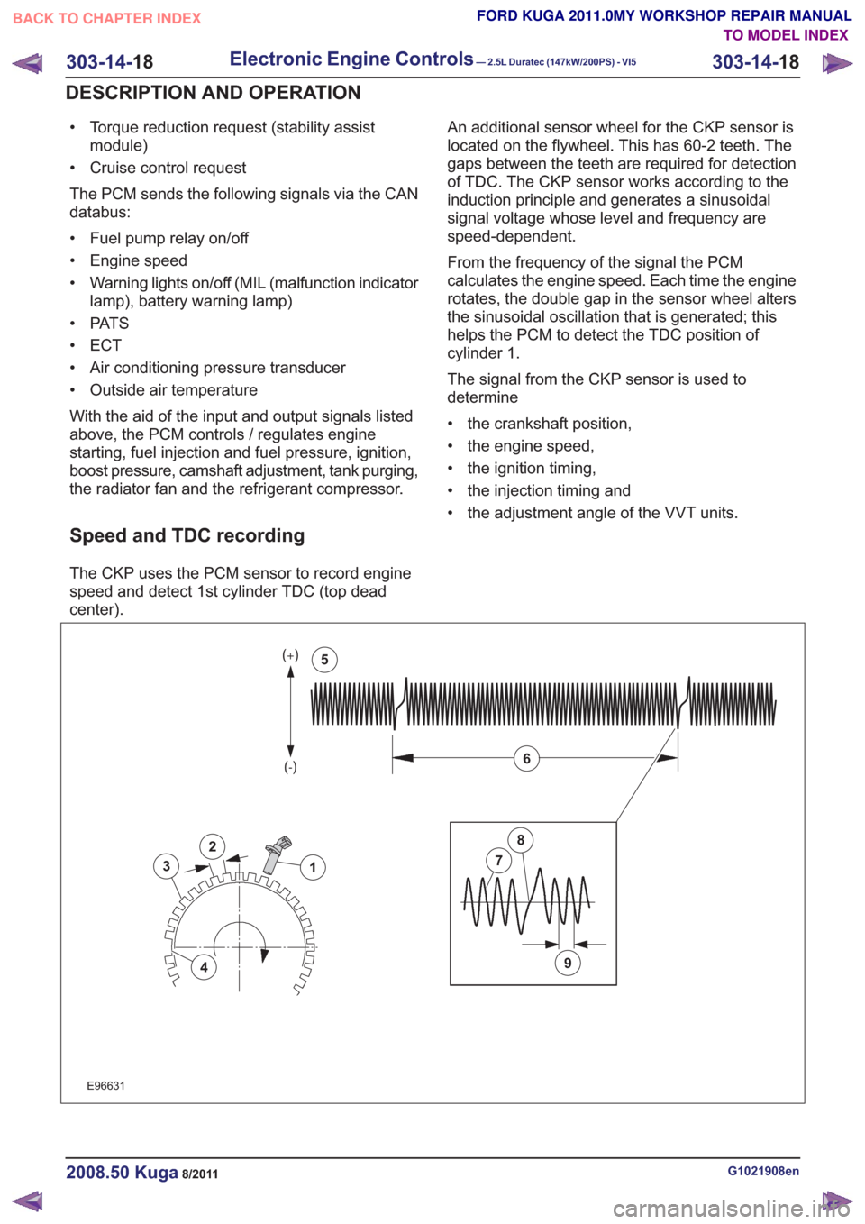
The CKP uses the PCM sensor to record engine
speed and detect 1st cylinder TDC (top dead
center). An additional sensor wheel for the CKP sensor is
located on the flywheel. This has 60-2 teeth. The
gaps between the teeth are required for detection
of TDC. The CKP sensor works according to the
induction principle and generates a sinusoidal
signal voltage whose level and frequency are
speed-dependent.
From the frequency of the signal the PCM
calculates the engine speed. Each time the engine
rotates, the double gap in the sensor wheel alters
the sinusoidal oscillation that is generated; this
helps the PCM to detect the TDC position of
cylinder 1.
The signal from the CKP sensor is used to
determine
• the crankshaft position,
• the engine speed,
• the ignition timing,
• the injection timing and
• the adjustment angle of the VVT units.
2
3
4
1
9
7
8
6
5
2
3
4
1
9
7
8
6
5
E96631
G1021908en2008.50 Kuga8/2011
303-14-
18
Electronic Engine Controls— 2.5L Duratec (147kW/200PS) - VI5303-14-
18
DESCRIPTION AND OPERATION
TO MODEL INDEX
BACK TO CHAPTER INDEX
FORD KUGA 2011.0MY WORKSHOP REPAIR MANUAL
Page 1851 of 2057
select-shift switch module transmits a downshift
signal to the TCM.
If you move the gear selector lever backwards (+),
an upshift signal is transmitted to the TCM. In the
instrument cluster, the symbol when the selector
lever is in the 'S' position changes from 'D' to the
current gear, for example 3.
The TCM transmits a signal to the select-shift
switch module to switch on the light emitting diode
for 'S' and to switch off all other light emitting
diodes. The TCM decides whether the shift process
is possible.
If the shift process is permitted, then the various
valves are activated according to the intended
combination for each gear.
In certain situations however, the TCM determines
the gear shifting. The following applies:
• If the vehicle is stationary, only 1st, 2nd and 3rdgears can be selected. 4th gear can be selected
at speeds over 30 km/h and 5th gear at speeds
over 40 km/h.
• The kickdown function is only available in the automatic transmission range 'D'
• Automatic gear changes into the next higher or next lower gear occur at fixed vehicle speeds
and fixed engine speeds
• The permitted engine speed for manual change down agree with that for the kickdown change
up, i.e. an engine speed of approximately 6000
rpm.
• If the temperature inside the transmission rises too high, the TCM takes control of the shift
decisions in order to select a gear in which
activation of torque converter lockup at the
current speed is possible
• Torque converter lockup is possible in 3rd, 4th and 5th gear. (1st and 2nd gears do not have
torque converter lockup)
The signal that specifies the position of the lever
to the select-shift switch module is generated as
follows in the selector lever position 'S': there is a
Hall sensor at the printed circuit board for the
module for each of the three selector lever
positions. A permanent magnet on the cover in the
selector lever affects the output signals to the
control module from the sensors. The control
module recognizes the position of the lever by the
differences in the signal properties.Selector lever from 'N' to 'R' position
The TCM only permits shifting to reverse gear if
the vehicle speed is less than 4.35 mph.
If the vehicle speed is greater than 7 km/h (approx.
4.35 mph), the clutch (C2) and the multi-plate brake
(B3) are not activated and the gearshift is thus
prevented.
Self-test and Diagnosis
The TCM monitors all the transaxle sensors and
electronic components including the PCM. If a fault
occurs, the driver is informed via a warning
indicator and a text message in the instrument
cluster. Faults are stored as DTCs in the fault
memory of the TCM and can be read out and
cleared using the IDS.
Temperature controlled torque converter
lockup
If heavy load and high ambient temperatures cause
an abnormal rise in the transmission temperature,
torque converter lockup is activated as often as
possible (temperature controlled lockup).
This reduces the slip and the heat developed in
the transmission. When the temperature drops
below +20 °C, torque converter lockup is not used.
Slip locking
When changing gear this function makes it possible
for the gears to engage more smoothly with
reduced vibration and less noise. In this mode, the
torque converter clutch is activated but not fully
locked.
The following conditions must be met for the
function to activate:
• Gear selector lever in position D or S.
• Gear 3, 4 or 5.
• The transmission input speed is 1100 rpm or more and the throttle plate opening 20 - 35%.
• The transmission fluid temperature is 40 - 120 °C.
Hill climbing
The TCM can change the shift pattern slightly when
driving uphill to avoid changing gear too often.
G1163605en2008.50 Kuga8/2011
307-01- 30
Automatic Transmission/Transaxle
— Vehicles With:
5-Speed Automatic Transaxle - AW55 AWD
307-01- 30
DESCRIPTION AND OPERATION
TO MODEL INDEX
BACK TO CHAPTER INDEX
FORD KUGA 2011.0MY WORKSHOP REPAIR MANUAL
Page 1866 of 2057
Output signals
Hard wired
• Item 8: PCM– Start inhibitor. Supplies the PCM with a signalthat indicates whether the engine can be
started or not.
• Item 9: Selector lever module (select-shift module)
– Controls the solenoid switch in the selectorlever unit.
• Position 10: PWM solenoid valve – shift pressure (SLS)
– Matches the line pressure to a shift pressureand is activated for certain gears.
• Position 11: PWM solenoid valve – main line pressure (SLT)
– Adjusts the linear line pressure for gearchanges without jolts.
• Position 12: PWM- solenoid valve – TCC (SLU) – Matches the line pressure to a torqueconverter lock-up pressure. Is also used for
certain gearshifts.
• Items 13 - 17: Shift solenoids S1 – S5 – The TCM checks which gear is engaged asthe solenoids become active in different
patterns.
Via the LIN data bus
• Item 7: Selector lever module (select-shift module)
– The TCM transmits a signal to the selectorlever module which activates the LED (light
emitting diode) in the selector mechanism
assembly according to the selector lever
position. Via the CAN data bus
• Item 2: GEM
– The selector lever module transmits a signalvia the TCM, which indicates that the selector
lever is locked in position P. The GEM uses
this information to control the ignition switch
key inhibit function.
– The TCM transmits a signal via the GEM to activate the back-up lamps.
• Item 3: Instrument Cluster – Current selector lever position. Used toindicate the selector lever position in the
instrument cluster.
– Check the warning lamps via the GEM. In the event of a fault, the general warning lamp
lights.
– Text messages in the instrument cluster via the GEM. The driver receives various
malfunction messages from the TCM.
– The TCM transmits signals on the CAN data bus to the PCM so that the MIL lights up in
the event of emissions-related faults.
• Item 4: PCM – Transmission fluid temperature, used tocompensate for increased loads at low fluid
temperatures.
– Gear selected, used by the engine so that it can compensate for different loads.
– Torque converter lockup, used by the engine so that it can compensate for different loads.
– Next gear planned by the TCM, used by the engine to compensate for different loads.
– Requirement for a reduced engine torque during gear shifts, the engine reduces the
engine torque during gear shifts.
– Torque limiting requirement, the engine limits the engine torque according to the gear
engaged.
• Item 5: ABS module – Current gear, used to transmit a signal, notfor shift control.
– Vehicle speed, used as reserve.
Control valve assembly
G1163605en2008.50 Kuga8/2011
307-01- 45
Automatic Transmission/Transaxle
— Vehicles With:
5-Speed Automatic Transaxle - AW55 AWD
307-01- 45
DESCRIPTION AND OPERATION
TO MODEL INDEX
BACK TO CHAPTER INDEX
FORD KUGA 2011.0MY WORKSHOP REPAIR MANUAL
Page 1970 of 2057
Fuel System — Vehicles With: Fuel Additive Tank
General EquipmentFord diagnostic equipment
Principles of Operation
WARNINGS:
This procedure involves fuel additive
handling. Be prepared for fuel additive
spillage at all times and always observe
fuel handling precautions. Failure to follow
these instructions may result in personal
injury.
Eye, hand, ear protection and protective
clothing are required to be worn during
any general service or removal and
installation service procedure of fuel
additive system components. Failure to
follow this instruction may result in
personal injury.
In case of fuel additive fluid contact with
the skin or the eyes, flush immediately with
water for a minimum of 15 minutes and
seek prompt medical attention. Failure to
follow these instructions may result in
personal injury.
If fuel additive fluid is swallowed, call a
physician immediately. Rinse mouth
immediately with water, do not induce
vomiting. Failure to follow these
instructions may result in personal injury.
Always provide adequate ventilation when
working on the fuel additive fluid system
or related components. Failure to follow
these instructions may result in personal
injury.
Do not smoke or carry lighted tobacco or
open flame of any type when working on
or near any fuel related components.
Highly flammable vapors are always
present and may ignite. Failure to follow
these instructions may result in personal
injury.
CAUTION: Make sure the workshop area
in which the vehicle is being worked on is
as clean and as dust free as possible.
Foreign matter from working on clutches,
brakes or from machining or welding
operations can contaminate the fuel
system and may result in later malfunction. The fuel additive system is an on-board system
that allows the injection of an additive at each
refueling operation by the customer. The additive
quantity is proportional to the fuel quantity that has
been added. The fuel additive system module
controls the amount of additive fluid entering the
fuel tank at each refueling, A switch mounted on
the fuel filler flap is used to detect the start of the
refueling event and the fuel gauge that is mounted
within the fuel tank informs the fuel additive tank
module the quantity of actual fuel added.
Inspection and Verification
1. Verify the customer concern.
2. Visually inspect for obvious signs of leakage
and mechanical or electrical damage.
Visual Inspection Chart
Electrical
Mechanical
– Fuse(s)
– Fuel filler switch andmagnet
– Wiring harness(s)
– Electrical connector(s)
– Fuel additive system module
– Fuel additive tank module
– Instrument cluster
– Powertrain Control Module (PCM)
– Fuel level sensor
– Fuel additive tank
– Fuel additive tank
line(s)
– Fuel additive tank pipe(s)
– Fuel additive tank connector(s)
– Fuel tank filler cap
3. If an obvious cause for an observed or reported concern is found, correct the cause (if possible)
before proceeding to the next step
4. If the cause is not visually evident, REFER to the Ford diagnostic equipment.
G1080718en2008.50 Kuga8/2011
310-00- 2
Fuel System - General Information
310-00- 2
DIAGNOSIS AND TESTING
TO MODEL INDEX
BACK TO CHAPTER INDEX
FORD KUGA 2011.0MY WORKSHOP REPAIR MANUAL
Page 1988 of 2057
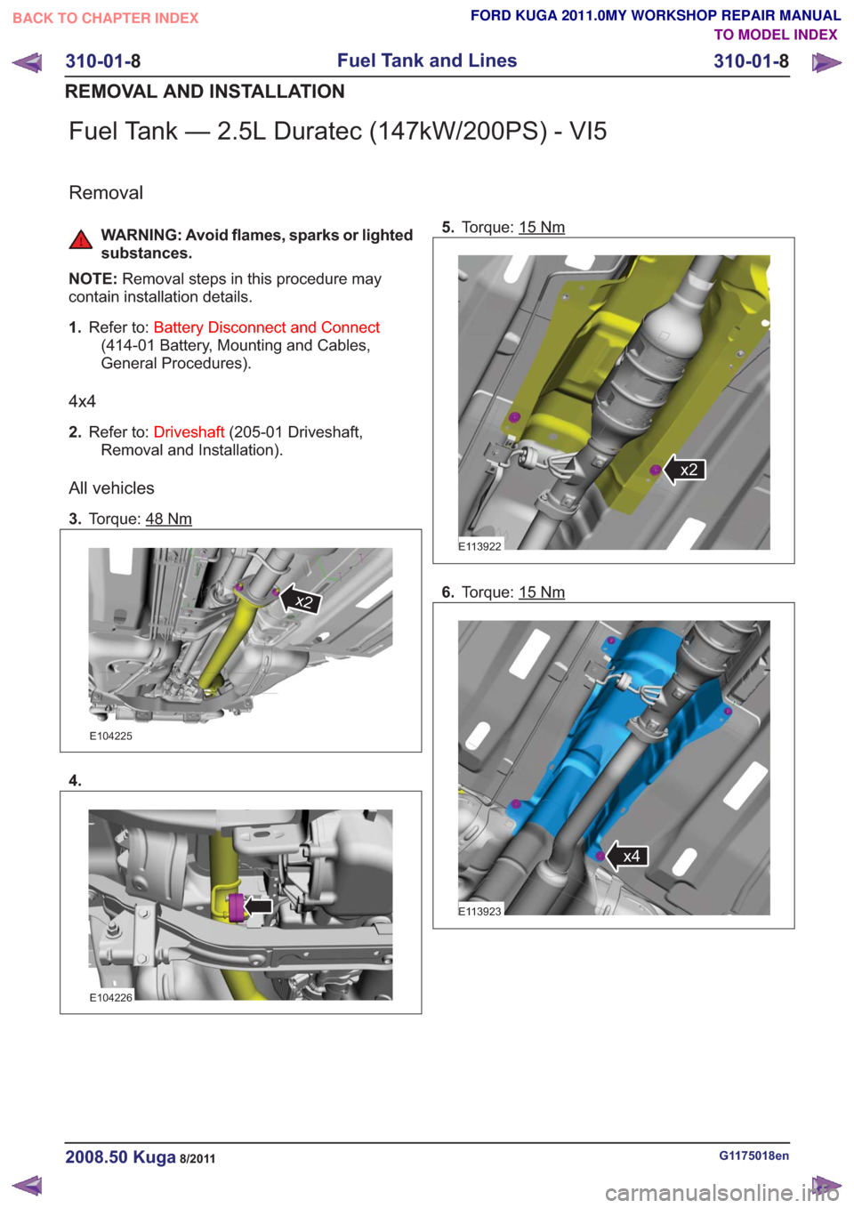
Fuel Tank — 2.5L Duratec (147kW/200PS) - VI5
Removal
WARNING: Avoid flames, sparks or lighted
substances.
NOTE: Removal steps in this procedure may
contain installation details.
1. Refer to: Battery Disconnect and Connect
(414-01 Battery, Mounting and Cables,
General Procedures).
4x4
2. Refer to: Driveshaft (205-01 Driveshaft,
Removal and Installation).
All vehicles
3. Torque: 48Nm
x2x2
E104225
4.
E104226
5.Torque: 15Nm
E113922
x2
6.Torque: 15Nm
x4x4
E113923
G1175018en2008.50 Kuga8/2011
310-01- 8
Fuel Tank and Lines
310-01- 8
REMOVAL AND INSTALLATION
TO MODEL INDEX
BACK TO CHAPTER INDEX
FORD KUGA 2011.0MY WORKSHOP REPAIR MANUAL
Page 1994 of 2057
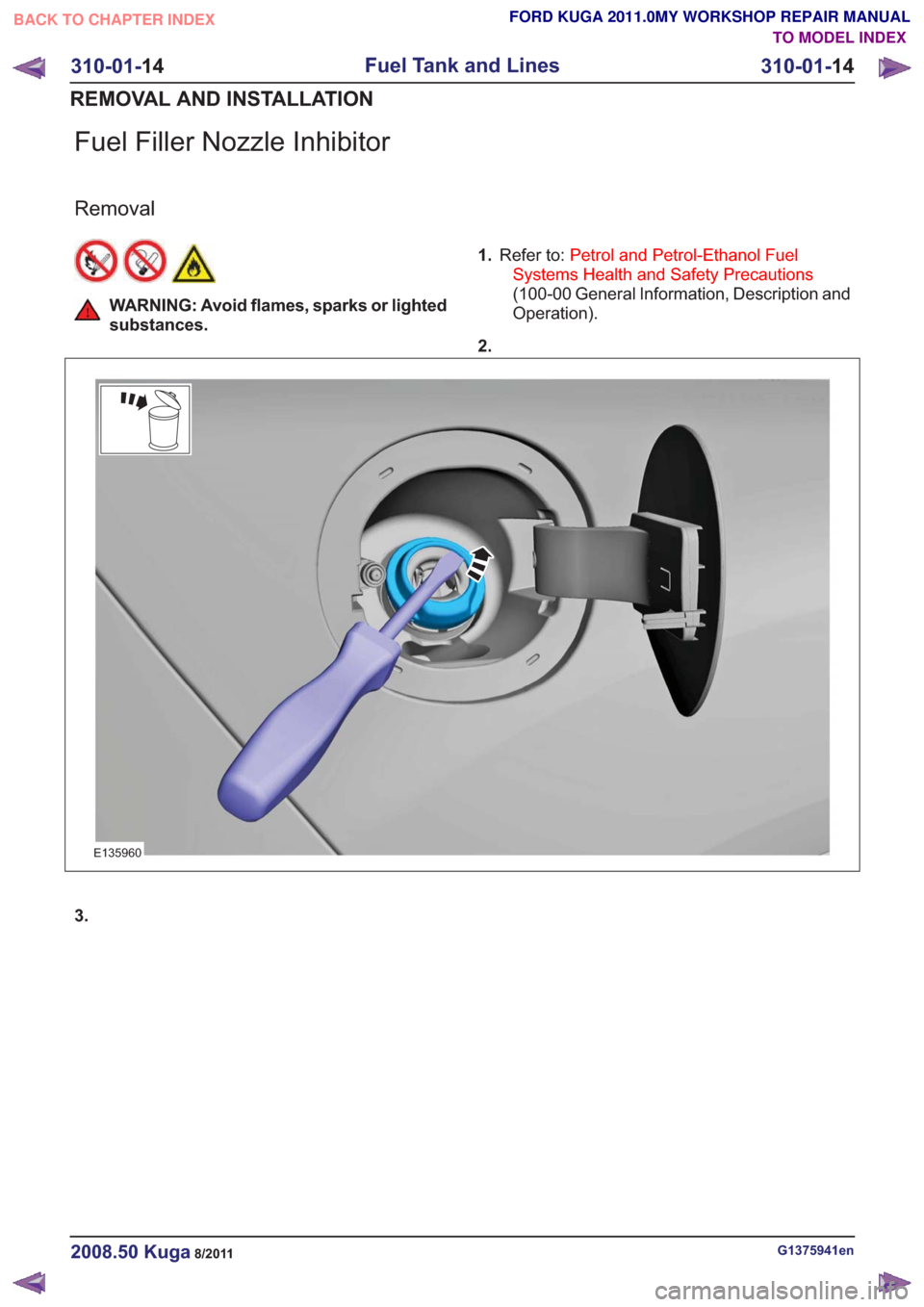
Fuel Filler Nozzle Inhibitor
Removal
WARNING: Avoid flames, sparks or lighted
substances.1.
Refer to: Petrol and Petrol-Ethanol Fuel
Systems Health and Safety Precautions
(100-00 General Information, Description and
Operation).
2.
E135960
3.
G1375941en2008.50 Kuga8/2011
310-01- 14
Fuel Tank and Lines
310-01- 14
REMOVAL AND INSTALLATION
TO MODEL INDEX
BACK TO CHAPTER INDEX
FORD KUGA 2011.0MY WORKSHOP REPAIR MANUAL