211-00 FORD KUGA 2011 1.G Workshop Manual
[x] Cancel search | Manufacturer: FORD, Model Year: 2011, Model line: KUGA, Model: FORD KUGA 2011 1.GPages: 2057
Page 85 of 2057
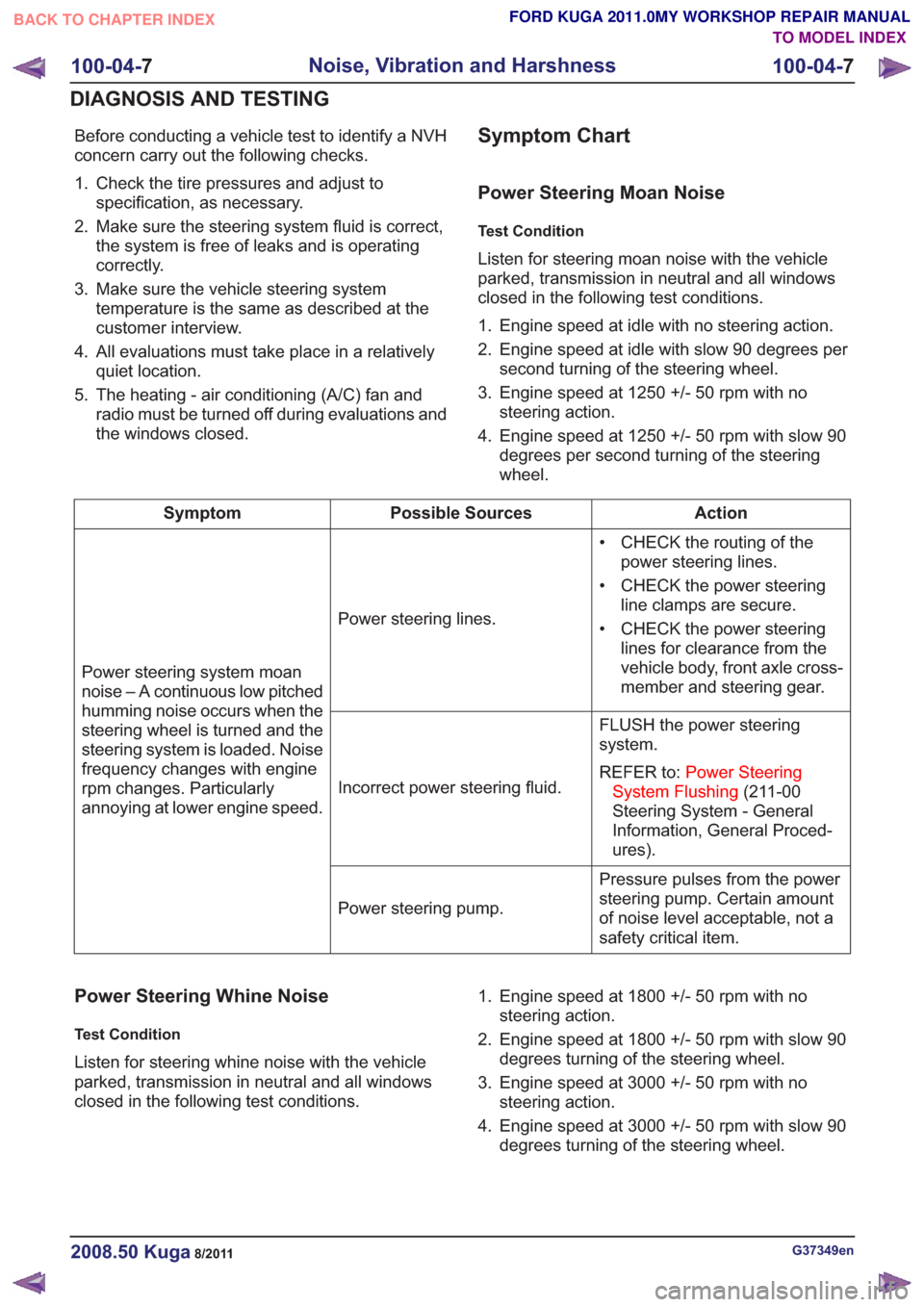
Before conducting a vehicle test to identify a NVH
concern carry out the following checks.
1. Check the tire pressures and adjust tospecification, as necessary.
2. Make sure the steering system fluid is correct, the system is free of leaks and is operating
correctly.
3. Make sure the vehicle steering system temperature is the same as described at the
customer interview.
4. All evaluations must take place in a relatively quiet location.
5. The heating - air conditioning (A/C) fan and radio must be turned off during evaluations and
the windows closed.Symptom Chart
Power Steering Moan Noise
Test Condition
Listen for steering moan noise with the vehicle
parked, transmission in neutral and all windows
closed in the following test conditions.
1. Engine speed at idle with no steering action.
2. Engine speed at idle with slow 90 degrees persecond turning of the steering wheel.
3. Engine speed at 1250 +/- 50 rpm with no steering action.
4. Engine speed at 1250 +/- 50 rpm with slow 90 degrees per second turning of the steering
wheel.
Action
Possible Sources
Symptom
• CHECK the routing of thepower steering lines.
• CHECK the power steering line clamps are secure.
• CHECK the power steering lines for clearance from the
vehicle body, front axle cross-
member and steering gear.
Power steering lines.
Power steering system moan
noise – A continuous low pitched
humming noise occurs when the
steering wheel is turned and the
steering system is loaded. Noise
frequency changes with engine
rpm changes. Particularly
annoying at lower engine speed. FLUSH the power steering
system.
REFER to:
Power Steering
System Flushing (211-00
Steering System - General
Information, General Proced-
ures).
Incorrect power steering fluid.
Pressure pulses from the power
steering pump. Certain amount
of noise level acceptable, not a
safety critical item.
Power steering pump.
Power Steering Whine Noise
Test Condition
Listen for steering whine noise with the vehicle
parked, transmission in neutral and all windows
closed in the following test conditions. 1. Engine speed at 1800 +/- 50 rpm with no
steering action.
2. Engine speed at 1800 +/- 50 rpm with slow 90 degrees turning of the steering wheel.
3. Engine speed at 3000 +/- 50 rpm with no steering action.
4. Engine speed at 3000 +/- 50 rpm with slow 90 degrees turning of the steering wheel.
G37349en2008.50 Kuga8/2011
100-04- 7
Noise, Vibration and Harshness
100-04- 7
DIAGNOSIS AND TESTING
TO MODEL INDEX
BACK TO CHAPTER INDEX
FORD KUGA 2011.0MY WORKSHOP REPAIR MANUAL
Page 86 of 2057
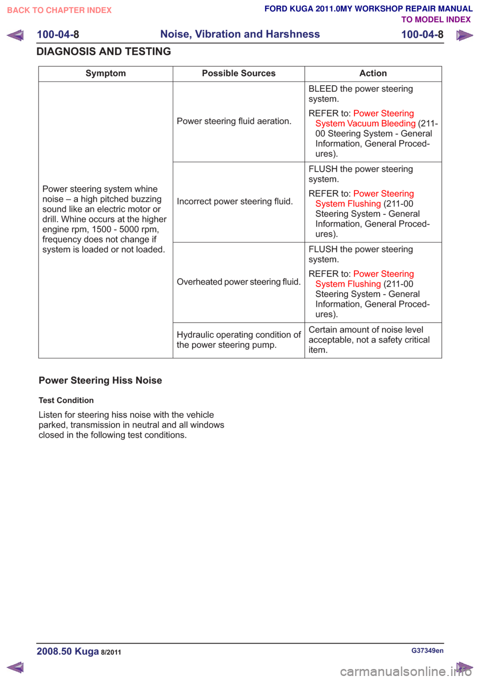
Action
Possible Sources
Symptom
BLEED the power steering
system.
REFER to:Power Steering
System Vacuum Bleeding (211-
00 Steering System - General
Information, General Proced-
ures).
Power steering fluid aeration.
Power steering system whine
noise – a high pitched buzzing
sound like an electric motor or
drill. Whine occurs at the higher
engine rpm, 1500 - 5000 rpm,
frequency does not change if
system is loaded or not loaded. FLUSH the power steering
system.
REFER to:
Power Steering
System Flushing (211-00
Steering System - General
Information, General Proced-
ures).
Incorrect power steering fluid.
FLUSH the power steering
system.
REFER to:Power Steering
System Flushing (211-00
Steering System - General
Information, General Proced-
ures).
Overheated power steering fluid.
Certain amount of noise level
acceptable, not a safety critical
item.
Hydraulic operating condition of
the power steering pump.
Power Steering Hiss Noise
Test Condition
Listen for steering hiss noise with the vehicle
parked, transmission in neutral and all windows
closed in the following test conditions.
G37349en2008.50 Kuga8/2011
100-04-
8
Noise, Vibration and Harshness
100-04- 8
DIAGNOSIS AND TESTING
TO MODEL INDEX
BACK TO CHAPTER INDEX
FORD KUGA 2011.0MY WORKSHOP REPAIR MANUAL
Page 93 of 2057
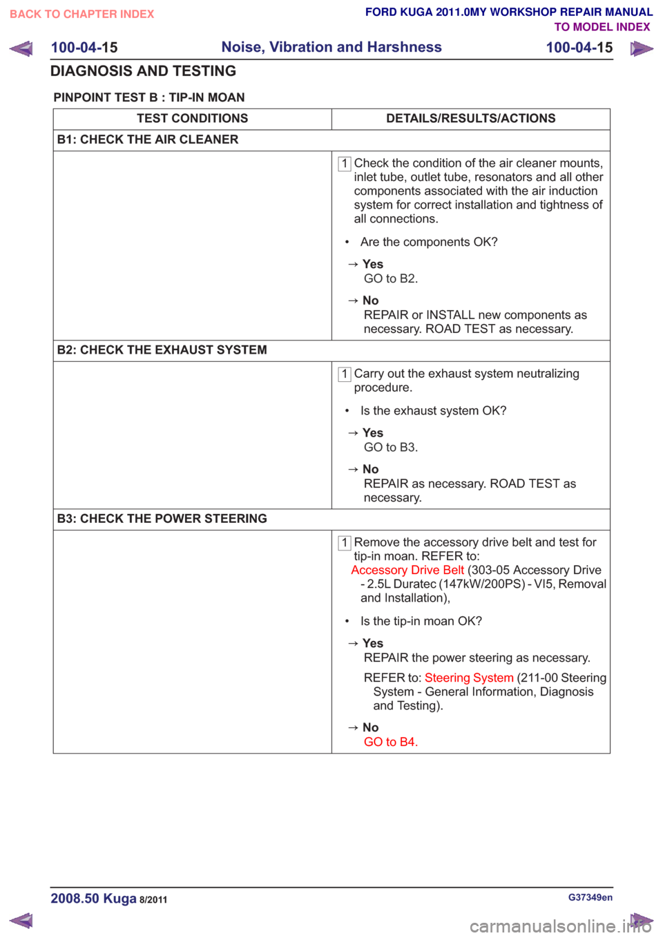
PINPOINT TEST B : TIP-IN MOAN
DETAILS/RESULTS/ACTIONS
TEST CONDITIONS
B1: CHECK THE AIR CLEANER
1 Check the condition of the air cleaner mounts,
inlet tube, outlet tube, resonators and all other
components associated with the air induction
system for correct installation and tightness of
all connections.
• Are the components OK?
zYe s GO to B2.
zNoREPAIR or INSTALL new components as
necessary. ROAD TEST as necessary.
B2: CHECK THE EXHAUST SYSTEM
1 Carry out the exhaust system neutralizing
procedure.
• Is the exhaust system OK?
zYe s GO to B3.
zNoREPAIR as necessary. ROAD TEST as
necessary.
B3: CHECK THE POWER STEERING
1 Remove the accessory drive belt and test for
tip-in moan. REFER to:
Accessory Drive Belt (303-05 Accessory Drive
- 2.5L Duratec (147kW/200PS) - VI5, Removal
and Installation),
• Is the tip-in moan OK?
zYe s REPAIR the power steering as necessary.
REFER to: Steering System (211-00 Steering
System - General Information, Diagnosis
and Testing).
zNo
GO to B4.
G37349en2008.50 Kuga8/2011
100-04- 15
Noise, Vibration and Harshness
100-04- 15
DIAGNOSIS AND TESTING
TO MODEL INDEX
BACK TO CHAPTER INDEX
FORD KUGA 2011.0MY WORKSHOP REPAIR MANUAL
Page 100 of 2057
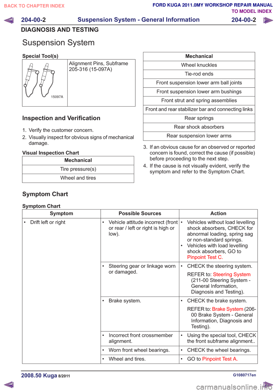
Suspension System
Special Tool(s)Alignment Pins, Subframe
205-316 (15-097A)
15097A
Inspection and Verification
1. Verify the customer concern.
2. Visually inspect for obvious signs of mechanicaldamage.
Visual Inspection Chart
Mechanical
Tire pressure(s) Wheel and tires
Mechanical
Wheel knuckles Tie-rod ends
Front suspension lower arm ball joints Front suspension lower arm bushings Front strut and spring assemblies
Front and rear stabilizer bar and connecting links Rear springs
Rear shock absorbers
Rear suspension lower arms
3. If an obvious cause for an observed or reported concern is found, correct the cause (if possible)
before proceeding to the next step.
4. If the cause is not visually evident, verify the symptom and refer to the Symptom Chart.
Symptom Chart
Symptom Chart
Action
Possible Sources
Symptom
• Vehicles without load levellingshock absorbers, CHECK for
abnormal loading, spring sag
or non-standard springs.
• Vehicles with load levelling shock absorbers, GO to
Pinpoint Test C.
• Vehicle attitude incorrect (front
or rear / left or right is high or
low).
• Drift left or right
• CHECK the steering system.REFER to: Steering System
(211-00 Steering System -
General Information,
Diagnosis and Testing).
• Steering gear or linkage worn
or damaged.
• CHECK the brake system.REFER to: Brake System (206-
00 Brake System - General
Information, Diagnosis and
Testing).
• Brake system.
• Using the special tool, CHECKthe front subframe alignment..
• Incorrect front crossmember
alignment.
• CHECK the wheel bearings.
• Worn front wheel bearings.
• GO toPinpoint Test A.
• Wheel and tires.
G1080717en2008.50 Kuga8/2011
204-00- 2
Suspension System - General Information
204-00- 2
DIAGNOSIS AND TESTING
TO MODEL INDEX
BACK TO CHAPTER INDEX
FORD KUGA 2011.0MY WORKSHOP REPAIR MANUAL
Page 1158 of 2057
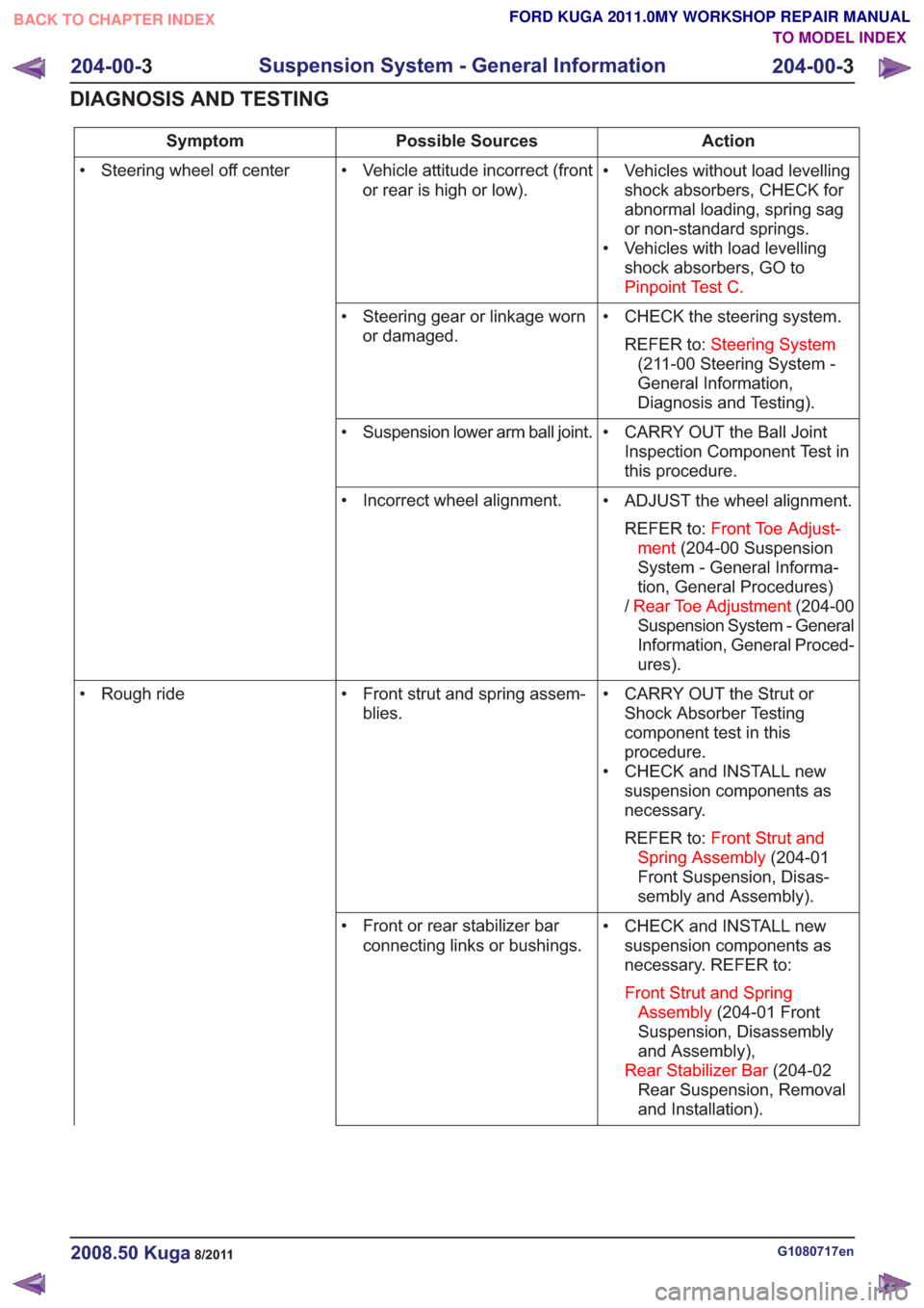
Action
Possible Sources
Symptom
• Vehicles without load levellingshock absorbers, CHECK for
abnormal loading, spring sag
or non-standard springs.
• Vehicles with load levelling shock absorbers, GO to
Pinpoint Test C.
• Vehicle attitude incorrect (front
or rear is high or low).
• Steering wheel off center
• CHECK the steering system.REFER to: Steering System
(211-00 Steering System -
General Information,
Diagnosis and Testing).
• Steering gear or linkage worn
or damaged.
• CARRY OUT the Ball JointInspection Component Test in
this procedure.
• Suspension lower arm ball joint.
• ADJUST the wheel alignment.REFER to: Front Toe Adjust-
ment (204-00 Suspension
System - General Informa-
tion, General Procedures)
/ Rear Toe Adjustment (204-00
Suspension System - General
Information, General Proced-
ures).
• Incorrect wheel alignment.
• CARRY OUT the Strut orShock Absorber Testing
component test in this
procedure.
• CHECK and INSTALL new suspension components as
necessary.
REFER to: Front Strut and
Spring Assembly (204-01
Front Suspension, Disas-
sembly and Assembly).
• Front strut and spring assem-
blies.
• Rough ride
• CHECK and INSTALL newsuspension components as
necessary. REFER to:
Front Strut and Spring Assembly (204-01 Front
Suspension, Disassembly
and Assembly),
Rear Stabilizer Bar (204-02
Rear Suspension, Removal
and Installation).
• Front or rear stabilizer bar
connecting links or bushings.
G1080717en2008.50 Kuga8/2011
204-00- 3
Suspension System - General Information
204-00- 3
DIAGNOSIS AND TESTING
TO MODEL INDEX
BACK TO CHAPTER INDEX
FORD KUGA 2011.0MY WORKSHOP REPAIR MANUAL
Page 1160 of 2057
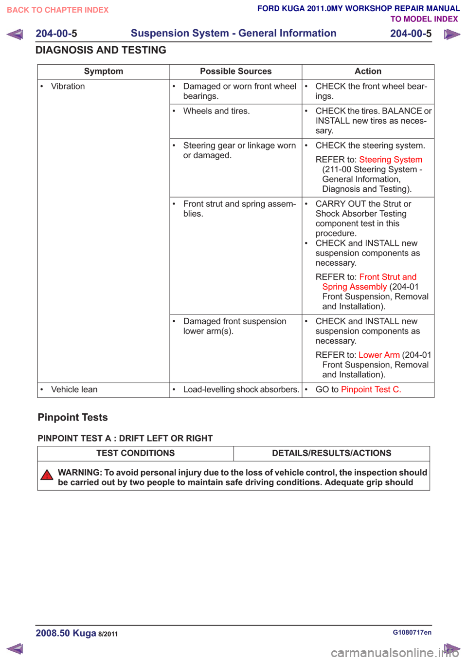
Action
Possible Sources
Symptom
• CHECK the front wheel bear-ings.
• Damaged or worn front wheel
bearings.
• Vibration
• CHECK the tires. BALANCE orINSTALL new tires as neces-
sary.
• Wheels and tires.
• CHECK the steering system.REFER to: Steering System
(211-00 Steering System -
General Information,
Diagnosis and Testing).
• Steering gear or linkage worn
or damaged.
• CARRY OUT the Strut orShock Absorber Testing
component test in this
procedure.
• CHECK and INSTALL new suspension components as
necessary.
REFER to: Front Strut and
Spring Assembly (204-01
Front Suspension, Removal
and Installation).
• Front strut and spring assem-
blies.
• CHECK and INSTALL newsuspension components as
necessary.
REFER to: Lower Arm (204-01
Front Suspension, Removal
and Installation).
• Damaged front suspension
lower arm(s).
• GO toPinpoint Test C.
• Load-levelling shock absorbers.
• Vehicle lean
Pinpoint Tests
PINPOINT TEST A : DRIFT LEFT OR RIGHT
DETAILS/RESULTS/ACTIONS
TEST CONDITIONS
WARNING: To avoid personal injury due to the loss of vehicle control, the inspection should
be carried out by two people to maintain safe driving conditions. Adequate grip should
G1080717en2008.50 Kuga8/2011
204-00- 5
Suspension System - General Information
204-00- 5
DIAGNOSIS AND TESTING
TO MODEL INDEX
BACK TO CHAPTER INDEX
FORD KUGA 2011.0MY WORKSHOP REPAIR MANUAL
Page 1298 of 2057
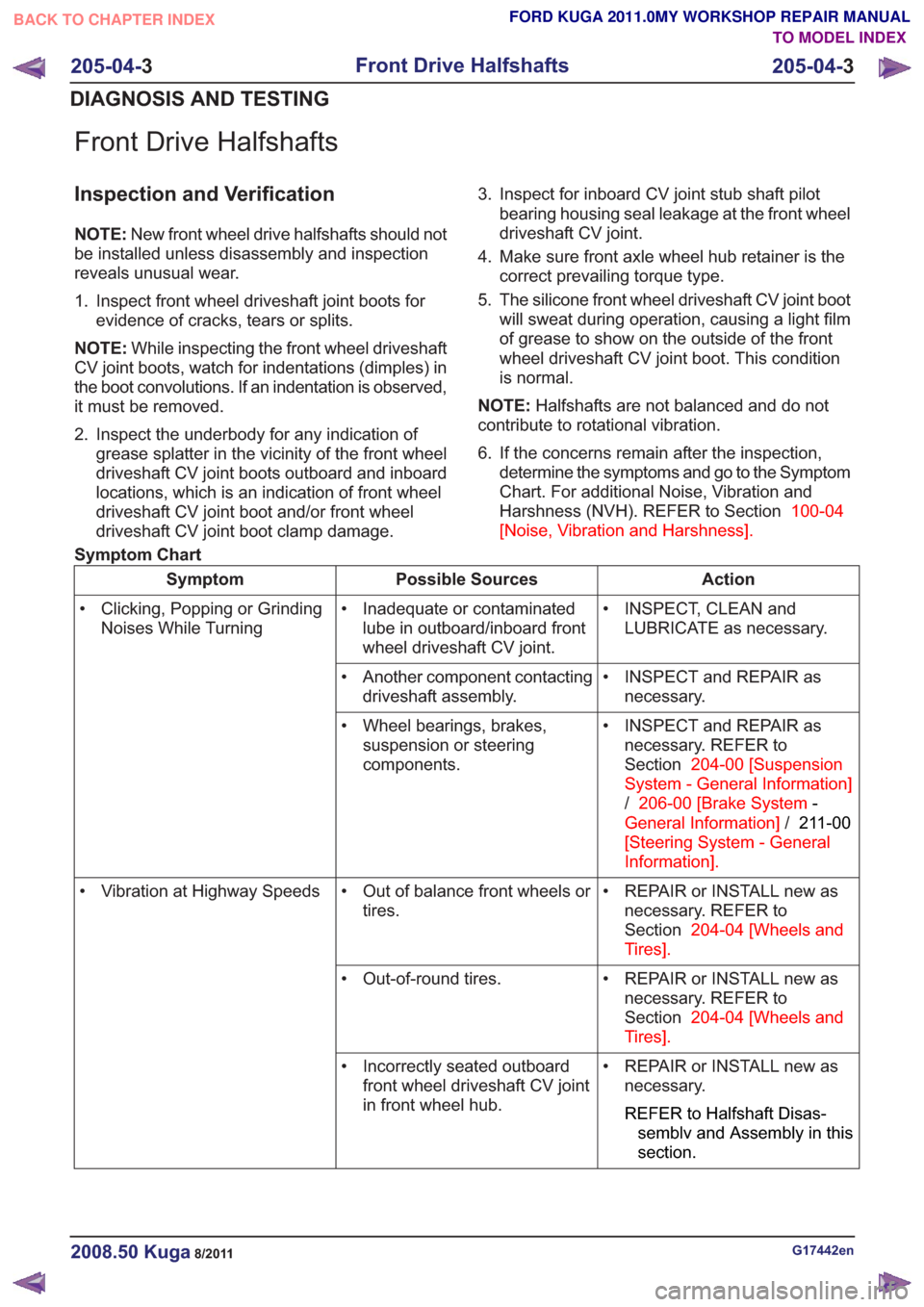
Front Drive Halfshafts
Inspection and Verification
NOTE:New front wheel drive halfshafts should not
be installed unless disassembly and inspection
reveals unusual wear.
1. Inspect front wheel driveshaft joint boots for evidence of cracks, tears or splits.
NOTE: While inspecting the front wheel driveshaft
CV joint boots, watch for indentations (dimples) in
the boot convolutions. If an indentation is observed,
it must be removed.
2. Inspect the underbody for any indication of grease splatter in the vicinity of the front wheel
driveshaft CV joint boots outboard and inboard
locations, which is an indication of front wheel
driveshaft CV joint boot and/or front wheel
driveshaft CV joint boot clamp damage. 3. Inspect for inboard CV joint stub shaft pilot
bearing housing seal leakage at the front wheel
driveshaft CV joint.
4. Make sure front axle wheel hub retainer is the correct prevailing torque type.
5. The silicone front wheel driveshaft CV joint boot will sweat during operation, causing a light film
of grease to show on the outside of the front
wheel driveshaft CV joint boot. This condition
is normal.
NOTE: Halfshafts are not balanced and do not
contribute to rotational vibration.
6. If the concerns remain after the inspection, determine the symptoms and go to the Symptom
Chart. For additional Noise, Vibration and
Harshness (NVH). REFER to Section 100-04
[Noise, Vibration and Harshness] .
Symptom Chart
Action
Possible Sources
Symptom
• INSPECT, CLEAN andLUBRICATE as necessary.
• Inadequate or contaminated
lube in outboard/inboard front
wheel driveshaft CV joint.
• Clicking, Popping or Grinding
Noises While Turning
• INSPECT and REPAIR asnecessary.
• Another component contacting
driveshaft assembly.
• INSPECT and REPAIR asnecessary. REFER to
Section 204-00 [Suspension
System - General Information]
/ 206-00 [Brake System -
General Information] /211-00
[Steering System - General
Information] .
• Wheel bearings, brakes,
suspension or steering
components.
• REPAIR or INSTALL new asnecessary. REFER to
Section 204-04 [Wheels and
Tires] .
• Out of balance front wheels or
tires.
• Vibration at Highway Speeds
• REPAIR or INSTALL new asnecessary. REFER to
Section 204-04 [Wheels and
Tires] .
• Out-of-round tires.
• REPAIR or INSTALL new asnecessary.
REFER to Halfshaft Disas-
semblv and Assembly in this
section.
• Incorrectly seated outboard
front wheel driveshaft CV joint
in front wheel hub.
G17442en2008.50 Kuga8/2011
205-04- 3
Front Drive Halfshafts
205-04- 3
DIAGNOSIS AND TESTING
TO MODEL INDEX
BACK TO CHAPTER INDEX
FORD KUGA 2011.0MY WORKSHOP REPAIR MANUAL
Page 1442 of 2057
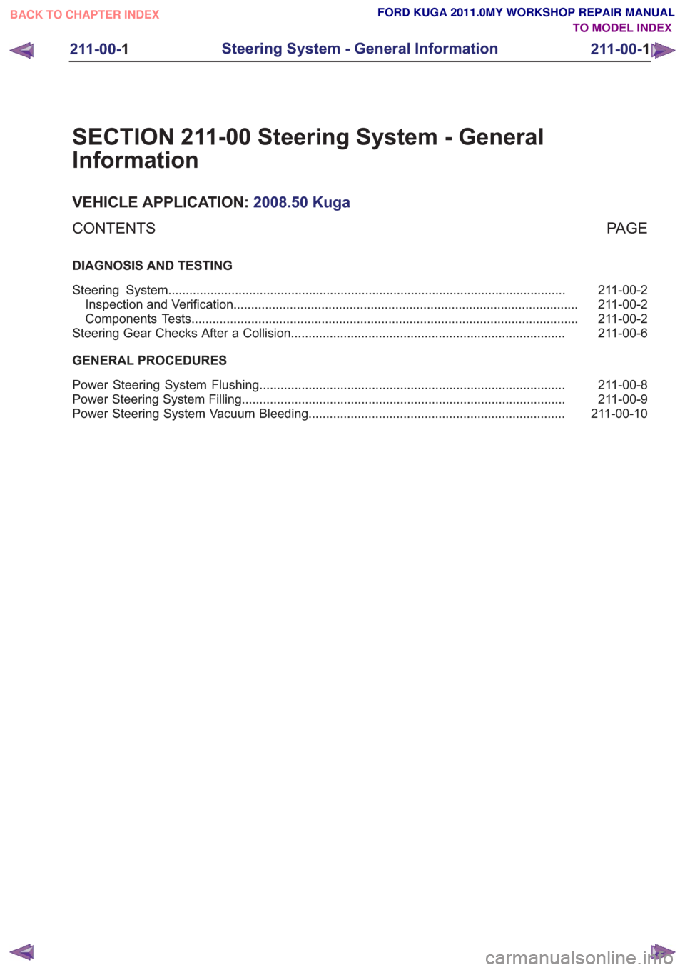
SECTION 211-00 Steering System - General
Information
VEHICLE APPLICATION:2008.50 Kuga
PA G E
CONTENTS
DIAGNOSIS AND TESTING
211-00-2
Steering System ........................................................................\
.........................................
211-00-2
Inspection and Verification ........................................................................\
..........................
211-00-2
Components Tests ........................................................................\
......................................
211-00-6
Steering Gear Checks After a Collision ........................................................................\
......
GENERAL PROCEDURES 211-00-8
Power Steering System Flushing ........................................................................\
...............
211-00-9
Power Steering System Filling ........................................................................\
....................
211-00-10
Power Steering System Vacuum Bleeding ........................................................................\
.
211-00-1
Steering System - General Information
211-00- 1
.
TO MODEL INDEX
BACK TO CHAPTER INDEX
FORD KUGA 2011.0MY WORKSHOP REPAIR MANUAL
Page 1443 of 2057
Steering System
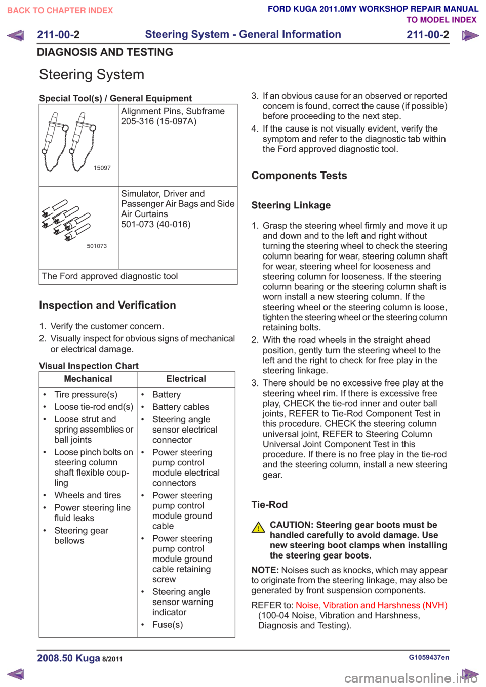
Special Tool(s) / General EquipmentAlignment Pins, Subframe
205-316 (15-097A)
15097
Simulator, Driver and
Passenger Air Bags and Side
Air Curtains
501-073 (40-016)
501073
The Ford approved diagnostic tool
Inspection and Verification
1. Verify the customer concern.
2. Visually inspect for obvious signs of mechanicalor electrical damage.
Visual Inspection Chart
Electrical
Mechanical
• Battery
• Battery cables
• Steering anglesensor electrical
connector
• Power steering pump control
module electrical
connectors
• Power steering pump control
module ground
cable
• Power steering pump control
module ground
cable retaining
screw
• Steering angle sensor warning
indicator
• Fuse(s)
• Tire pressure(s)
• Loose tie-rod end(s)
• Loose strut and
spring assemblies or
ball joints
• Loose pinch bolts on steering column
shaft flexible coup-
ling
• Wheels and tires
• Power steering line fluid leaks
• Steering gear bellows 3. If an obvious cause for an observed or reported
concern is found, correct the cause (if possible)
before proceeding to the next step.
4. If the cause is not visually evident, verify the symptom and refer to the diagnostic tab within
the Ford approved diagnostic tool.
Components Tests
Steering Linkage
1. Grasp the steering wheel firmly and move it upand down and to the left and right without
turning the steering wheel to check the steering
column bearing for wear, steering column shaft
for wear, steering wheel for looseness and
steering column for looseness. If the steering
column bearing or the steering column shaft is
worn install a new steering column. If the
steering wheel or the steering column is loose,
tighten the steering wheel or the steering column
retaining bolts.
2. With the road wheels in the straight ahead position, gently turn the steering wheel to the
left and the right to check for free play in the
steering linkage.
3. There should be no excessive free play at the steering wheel rim. If there is excessive free
play, CHECK the tie-rod inner and outer ball
joints, REFER to Tie-Rod Component Test in
this procedure. CHECK the steering column
universal joint, REFER to Steering Column
Universal Joint Component Test in this
procedure. If there is no free play in the tie-rod
and the steering column, install a new steering
gear.
Tie-Rod
CAUTION: Steering gear boots must be
handled carefully to avoid damage. Use
new steering boot clamps when installing
the steering gear boots.
NOTE: Noises such as knocks, which may appear
to originate from the steering linkage, may also be
generated by front suspension components.
REFER to: Noise, Vibration and Harshness (NVH)
(100-04 Noise, Vibration and Harshness,
Diagnosis and Testing).
G1059437en2008.50 Kuga8/2011
211-00- 2
Steering System - General Information
211-00- 2
DIAGNOSIS AND TESTING
TO MODEL INDEX
BACK TO CHAPTER INDEX
FORD KUGA 2011.0MY WORKSHOP REPAIR MANUAL
Page 1444 of 2057
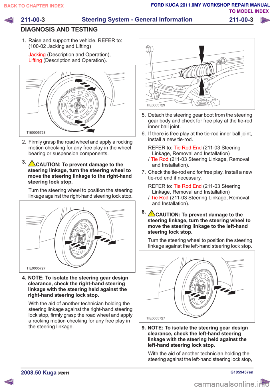
1. Raise and support the vehicle. REFER to:(100-02 Jacking and Lifting)
Jacking (Description and Operation),
Lifting (Description and Operation).
TIE0005728
2. Firmly grasp the road wheel and apply a rocking
motion checking for any free play in the wheel
bearing or suspension components.
3.
CAUTION: To prevent damage to the
steering linkage, turn the steering wheel to
move the steering linkage to the right-hand
steering lock stop.
Turn the steering wheel to position the steering
linkage against the right-hand steering lock stop.
TIE0005727
4. NOTE: To isolate the steering gear design clearance, check the right-hand steering
linkage with the steering held against the
right-hand steering lock stop.
With the aid of another technician holding the
steering linkage against the right-hand steering
lock stop, firmly grasp the road wheel and apply
a rocking motion checking for any free play in
the steering linkage.
TIE0005729
5. Detach the steering gear boot from the steering gear body and check for free play at the tie-rod
inner ball joint.
6. If there is free play at the tie-rod inner ball joint, install a new tie-rod.
REFER to: Tie Rod End (211-03 Steering
Linkage, Removal and Installation)
/ Tie Rod (211-03 Steering Linkage, Removal
and Installation).
7. Check the tie-rod end for free play. Install a new tie-rod end if necessary.
REFER to: Tie Rod End (211-03 Steering
Linkage, Removal and Installation)
/ Tie Rod (211-03 Steering Linkage, Removal
and Installation).
8.
CAUTION: To prevent damage to the
steering linkage, turn the steering wheel to
move the steering linkage to the left-hand
steering lock stop.
Turn the steering wheel to position the steering
linkage against the left-hand steering lock stop.
TIE0005727
9. NOTE: To isolate the steering gear design clearance, check the left-hand steering
linkage with the steering held against the
left-hand steering lock stop.
With the aid of another technician holding the
steering against the left-hand steering lock stop,
G1059437en2008.50 Kuga8/2011
211-00- 3
Steering System - General Information
211-00- 3
DIAGNOSIS AND TESTING
TO MODEL INDEX
BACK TO CHAPTER INDEX
FORD KUGA 2011.0MY WORKSHOP REPAIR MANUAL