Camera FORD KUGA 2011 1.G Workshop Manual
[x] Cancel search | Manufacturer: FORD, Model Year: 2011, Model line: KUGA, Model: FORD KUGA 2011 1.GPages: 2057
Page 200 of 2057
SECTION 413-13 Parking Aid
VEHICLE APPLICATION:
2008.50 Kuga
PAGE
CONTENTS
DESCRIPTION AND OPERATION
413-13-2
Parking Aid (Component Location).....................................................................................
413-13-5
Parking Aid (Overview).......................................................................................................
413-13-5
Parking aid sensors............................................................................................................
413-13-5
Front sensors detection range............................................................................................
413-13-6
Rear sensors detection range............................................................................................
413-13-6
Parking aid camera module................................................................................................
413-13-6
Parking Aid Camera...........................................................................................................
413-13-7
Parking Aid (System Operation and Component Description)...........................................
413-13-7
System Diagram.................................................................................................................
413-13-12
System Operation...............................................................................................................
413-13-12
Parking Aid......................................................................................................................
413-13-13
Parking Aid Camera........................................................................................................
413-13-15
Component Description......................................................................................................413-13-15Rear parking aid speaker................................................................................................
413-13-15Parking aid sensors........................................................................................................
413-13-15Parking aid module.........................................................................................................
413-13-16Front parking aid speaker...............................................................................................
413-13-16Parking aid switch...........................................................................................................
413-13-16Parking aid camera module............................................................................................
413-13-16Parking Aid Camera........................................................................................................
DIAGNOSIS AND TESTING 413-13-17
Parking Aid — Vehicles With: Front Parking Aid................................................................
413-13-17
Principles of Operation.......................................................................................................
413-13-17
Inspection and Verification..................................................................................................
413-13-17
Diagnostic Trouble Codes (DTC) Index..............................................................................
413-13-21
Symptom Chart...................................................................................................................
413-13-21
Pinpoint Tests.....................................................................................................................
413-13-29
Parking Aid — Vehicles With: Rear Parking Aid.................................................................
413-13-29
Principles of Operation.......................................................................................................
413-13-29
Inspection and Verification..................................................................................................
413-13-29
Diagnostic Trouble Codes (DTC) Index..............................................................................
413-13-32
Symptom Chart...................................................................................................................
413-13-32
Pinpoint Tests.....................................................................................................................
REMOVAL AND INSTALLATION 413-13-44
Parking Aid Module.............................................................................................................
413-13-45
Parking Aid Camera Module...............................................................................................
413-13-46
Parking Aid Camera............................................................................................................
413-13-48
Front Parking Aid Speaker.................................................................................................
413-13-49
Rear Parking Aid Speaker..................................................................................................
413-13-50
Front Parking Aid Sensor....................................................................................................
413-13-56
Rear Parking Aid Sensor.................................................................................................... 413-13-1
Parking Aid
413-13-1
.
TO MODEL INDEX
BACK TO CHAPTER INDEX
FORD KUGA 2011.0MY WORKSHOP REPAIR MANUAL
Page 205 of 2057
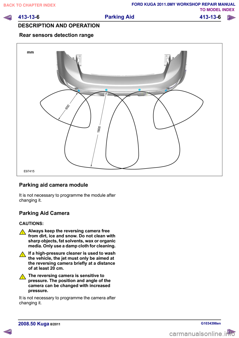
Rear sensors detection range
Parking aid camera module
It is not necessary to programme the module after
changing it.
Parking Aid Camera
CAUTIONS:
Always keep the reversing camera free
from dirt, ice and snow. Do not clean with
sharp objects, fat solvents, wax or organic
media. Only use a damp cloth for cleaning.
If a high-pressure cleaner is used to wash
the vehicle, the jet must only be aimed at
the reversing camera briefly at a distance
of at least 20 cm.
The reversing camera is sensitive to
pressure. The position and angle of the
camera can be changed with increased
pressure.
It is not necessary to programme the camera after
changing it. G1034398en
2008.50 Kuga 8/2011 413-13-6
Parking Aid
413-13-6
DESCRIPTION AND OPERATIONTO MODEL INDEX
BACK TO CHAPTER INDEX
FORD KUGA 2011.0MY WORKSHOP REPAIR MANUAL6001800mmE97415
Page 212 of 2057
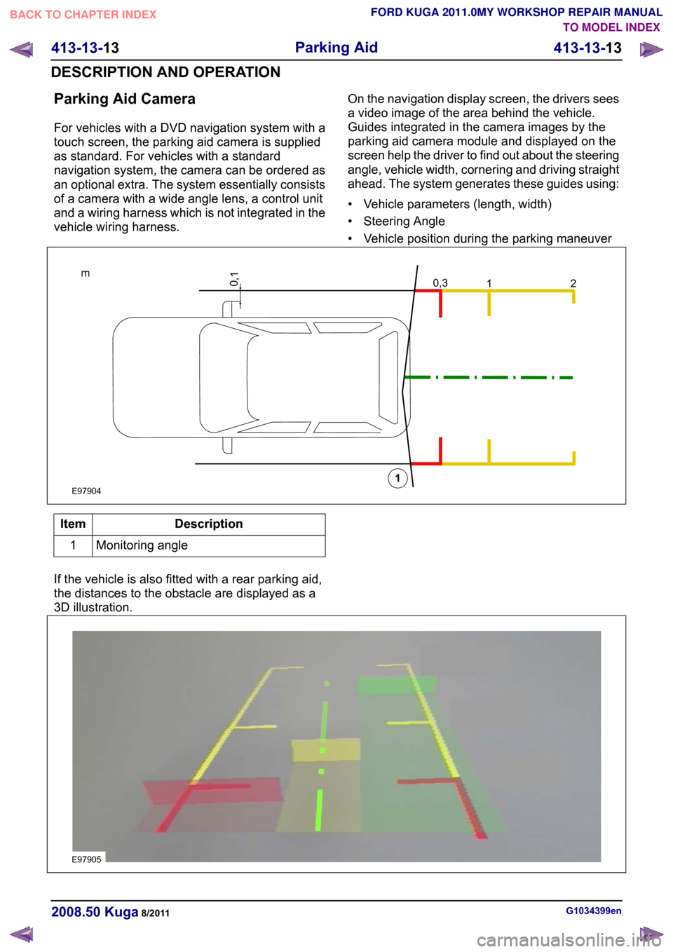
Parking Aid Camera
For vehicles with a DVD navigation system with a
touch screen, the parking aid camera is supplied
as standard. For vehicles with a standard
navigation system, the camera can be ordered as
an optional extra. The system essentially consists
of a camera with a wide angle lens, a control unit
and a wiring harness which is not integrated in the
vehicle wiring harness.
On the navigation display screen, the drivers sees
a video image of the area behind the vehicle.
Guides integrated in the camera images by the
parking aid camera module and displayed on the
screen help the driver to find out about the steering
angle, vehicle width, cornering and driving straight
ahead. The system generates these guides using:
• Vehicle parameters (length, width)
• Steering Angle
• Vehicle position during the parking maneuverDescription
Item
Monitoring angle
1
If the vehicle is also fitted with a rear parking aid,
the distances to the obstacle are displayed as a
3D illustration. G1034399en
2008.50 Kuga 8/2011 413-13-13
Parking Aid
413-13-13
DESCRIPTION AND OPERATIONTO MODEL INDEX
BACK TO CHAPTER INDEX
FORD KUGA 2011.0MY WORKSHOP REPAIR MANUAL0,3m120,11E97904 E97905
Page 215 of 2057
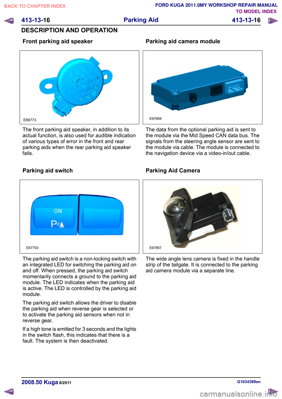
Front parking aid speaker
The front parking aid speaker, in addition to its
actual function, is also used for audible indication
of various types of error in the front and rear
parking aids when the rear parking aid speaker
fails.
Parking aid switch
The parking aid switch is a non-locking switch with
an integrated LED for switching the parking aid on
and off. When pressed, the parking aid switch
momentarily connects a ground to the parking aid
module. The LED indicates when the parking aid
is active. The LED is controlled by the parking aid
module.
The parking aid switch allows the driver to disable
the parking aid when reverse gear is selected or
to activate the parking aid sensors when not in
reverse gear.
If a high tone is emitted for 3 seconds and the lights
in the switch flash, this indicates that there is a
fault. The system is then deactivated. Parking aid camera module
The data from the optional parking aid is sent to
the module via the Mid Speed CAN data bus. The
signals from the steering angle sensor are sent to
the module via cable. The module is connected to
the navigation device via a video-in/out cable.
Parking Aid Camera
The wide angle lens camera is fixed in the handle
strip of the tailgate. It is connected to the parking
aid camera module via a separate line.
G1034399en
2008.50 Kuga 8/2011 413-13-16
Parking Aid
413-13-16
DESCRIPTION AND OPERATIONTO MODEL INDEX
BACK TO CHAPTER INDEX
FORD KUGA 2011.0MY WORKSHOP REPAIR MANUALE89773 E97703 E97856 E97857
Page 244 of 2057
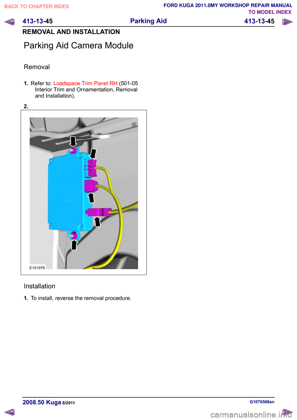
Parking Aid Camera Module
Removal
1.
Refer to: Loadspace Trim Panel RH (501-05
Interior Trim and Ornamentation, Removal
and Installation).
2. Installation
1.
To install, reverse the removal procedure. G1076568en
2008.50 Kuga 8/2011 413-13-45
Parking Aid
413-13-45
REMOVAL AND INSTALLATIONTO MODEL INDEX
BACK TO CHAPTER INDEX
FORD KUGA 2011.0MY WORKSHOP REPAIR MANUALE101978
Page 245 of 2057
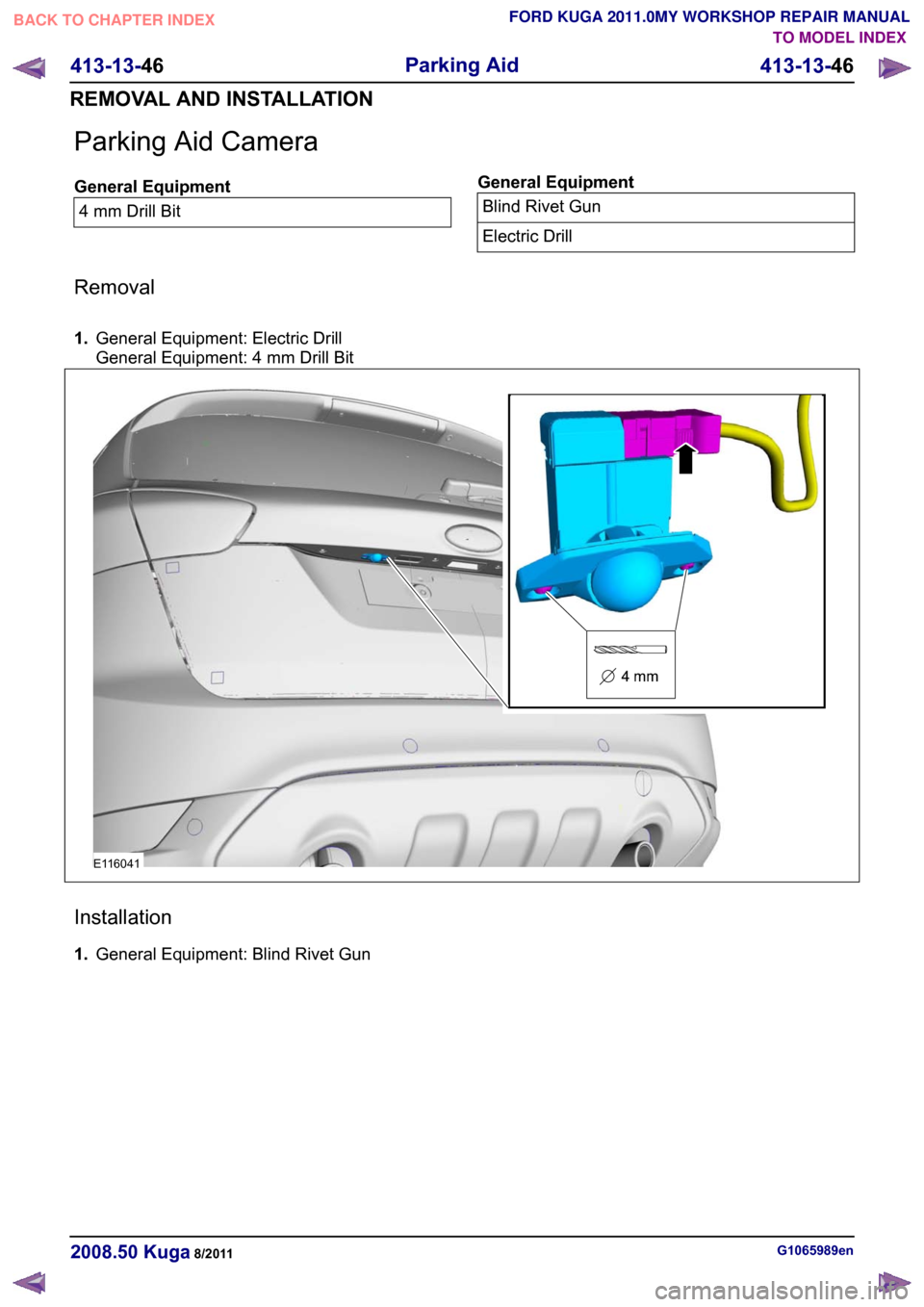
Parking Aid Camera
General Equipment
4 mm Drill Bit General Equipment
Blind Rivet Gun
Electric Drill
Removal
1. General Equipment: Electric Drill
General Equipment: 4 mm Drill Bit Installation
1.
General Equipment: Blind Rivet Gun G1065989en
2008.50 Kuga 8/2011 413-13-46
Parking Aid
413-13-46
REMOVAL AND INSTALLATIONTO MODEL INDEX
BACK TO CHAPTER INDEX
FORD KUGA 2011.0MY WORKSHOP REPAIR MANUALE116041
Page 380 of 2057

Description
Item
Reversing camera module (RVC)
10
Keyless vehicle module (KVM)
11
All-wheel drive control unit
12
RDM - Driver's side
13
RCM (restraints control module)
14
DDM (driver door module)
15
Instrument Cluster
16 Description
Item
High intensity discharge headlamp module
(optional)
17
ABS (anti-lock brake system) module or
electronic stability program module
18
PCM (powertrain control module)
19
The EATC (electronic automatic
temperature control) control module
20
Electrohydraulic power steering module
21 G1072290en
2008.50 Kuga 8/2011 418-00-3
Module Communications Network
418-00-3
DESCRIPTION AND OPERATIONTO MODEL INDEX
BACK TO CHAPTER INDEX
FORD KUGA 2011.0MY WORKSHOP REPAIR MANUAL
Page 383 of 2057

Description
Item
Medium speed CAN (controller area
network) bus (MS-CAN)
A
High speed CAN bus (HS-CAN)
B
LIN (local interconnect network) bus
C
Terminating resistors
Drive
DLC (data link connector)
E
GEMRefer to Component Description: ABS
(page ?)
1
Fuel fired booster heater /programmable
fuel fired booster heater
2
The EATC control module
3
Reversing camera module (RVC)
4
Parking aid module (PAM)
5
DDM6
Front driver's side switch unit
7
Driver's side RDM
8
PDM (Passenger Door Module)
9
Passenger side RDM
10
Audio unit/navigation unit
11
CD changer
12 Description
Item
Navigation system module - vehicles
equipped with DVD navigation system with
touch screen (not communicating with the
diagnostic unit)
13
Navigation system display - vehicles
equipped with DVD navigation system with
touch screen (not communicating with the
diagnostic unit)
14
Control module for electronic auxiliary
equipment (BVC)
15
RCM16
Keyless vehicle module (KVM)
17
Instrument Cluster
18
PCM19
Fuel additive system module.
20
ABS module or electronic stability program
module
21
Yaw rate sensor/lateral acceleration
sensor
22
Headlamp Leveling Module
23
All-wheel drive control unit
24
Electrohydraulic power steering module
25
System Operation
General
In a communications network (data bus system),
various modules of different systems are connected
to one another via one or several lines.
The data bus system is used exclusively for
transmitting data between the connected modules,
as well as between the connected modules and
the Ford diagnostic unit.
In a data bus system, complete data blocks are
transmitted instead of single on/off pulses. In
addition to the actual information, these data blocks
also contain data regarding the address of the
module to be addressed, the size of the data block
and information for monitoring the content of each
individual data block.
Data bus systems offer various advantages: • Simplified data transmission between the
modules due to a standardized protocol
• Fewer sensors and connectors
• Improved diagnostic options
• Lower costs
The DLC is connected to the various data bus
systems and to the power supply via the standard
16-pin GEM. The signal for the module
programming is also transferred via the DLC.
In a data bus system, if there is a break in one or
both lines or there is a short to ground or to voltage,
then communication between the modules and
with the Ford diagnostic unit is disturbed or is no
longer possible at all.
In order to be able to establish communication with
one another, the modules of the individual systems G1030779en
2008.50 Kuga 8/2011 418-00-6
Module Communications Network
418-00-6
DESCRIPTION AND OPERATIONTO MODEL INDEX
BACK TO CHAPTER INDEX
FORD KUGA 2011.0MY WORKSHOP REPAIR MANUAL