In-Vehicle Temperature Sensor FORD KUGA 2011 1.G Workshop Manual
[x] Cancel search | Manufacturer: FORD, Model Year: 2011, Model line: KUGA, Model: FORD KUGA 2011 1.GPages: 2057
Page 145 of 2057
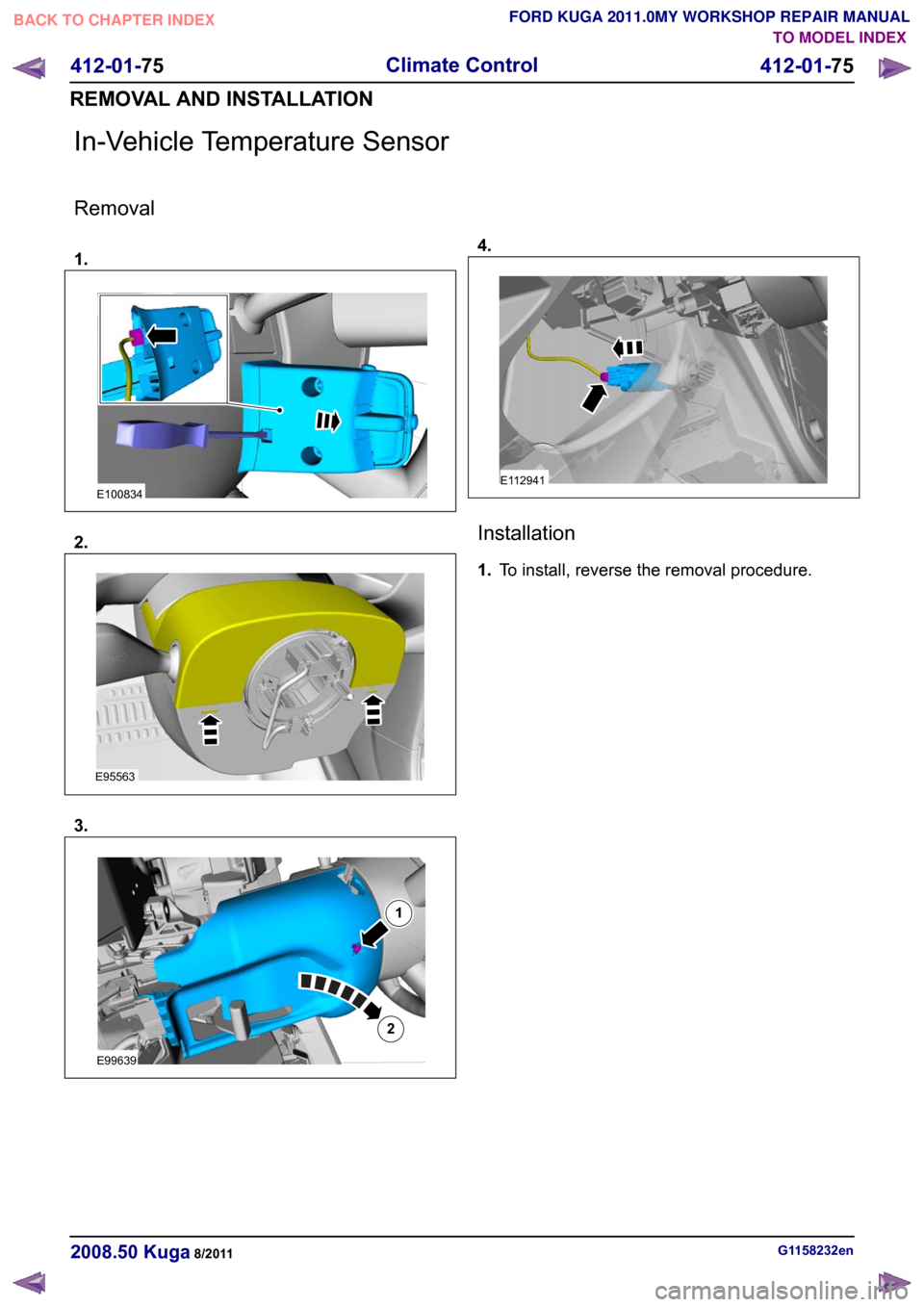
In-Vehicle Temperature Sensor
Removal
1.
2.
3. 4.
Installation
1.
To install, reverse the removal procedure. G1158232en
2008.50 Kuga 8/2011 412-01-75
Climate Control
412-01-75
REMOVAL AND INSTALLATIONTO MODEL INDEX
BACK TO CHAPTER INDEX
FORD KUGA 2011.0MY WORKSHOP REPAIR MANUALE100834 E95563 E9963912 E112941
Page 2028 of 2057

SECTION 412-01 Climate Control
VEHICLE APPLICATION:2008.50 Kuga
PA G E
CONTENTS
SPECIFICATIONS
412-01-3
Specifications ........................................................................\
..............................................
DESCRIPTION AND OPERATION 412-01-4
Climate Control (Component Location) ........................................................................\
......
412-01-10
Climate Control (Overview) ........................................................................\
........................
412-01-10
Pollen filter ........................................................................\
..................................................
412-01-10
Heat exchanger ........................................................................\
..........................................
412-01-10
Evaporator assembly ........................................................................\
..................................
412-01-10
Blower motor ........................................................................\
..............................................
412-01-11
Fault Memory Interrogation without diagnostics unit - vehicles with automatic temperature
control ........................................................................\
.......................................................
412-01-11
Switch over from Celsius to Fahrenheit ........................................................................\
......
412-01-12
Climate Control (System Operation and Component Description) .....................................
412-01-12
System Diagram ........................................................................\
.........................................
412-01-19
System Operation ........................................................................\
.......................................
412-01-19
Climate control housing ........................................................................\
..........................
412-01-22
Climate control ........................................................................\
........................................
412-01-24
Component Description ........................................................................\
..............................
412-01-24
Air conditioning compressor ........................................................................\
...................
412-01-24
Pollen filter ........................................................................\
..............................................
412-01-24
Control assembly, climate control - vehicles with manual temperature control ..............
412-01-25
Control assembly, climate control - vehicles with automatic temperature control ...........
412-01-25
Control assembly, climate control - vehicles with DVD navigation system with a touch
screen........................................................................\
................................................... 412-01-25
Climate control module - vehicles with DVD navigation system with a touch screen.....
412-01-25
Sun sensor - vehicles with automatic temperature control .............................................
412-01-26
In-vehicle temperature sensor ........................................................................\
................
412-01-26
Ambient temperature sensor ........................................................................\
..................
412-01-26
Blower motor ........................................................................\
...........................................
412-01-26
Blower control module - vehicles equipped with automatic temperature control ............
REMOVAL AND INSTALLATION 412-01-28
(34 626 4)
Air Conditioning (A/C) Compressor — 2.5L Duratec (147kW/200PS) - VI5 ....
412-01-29
Air Conditioning (A/C) Compressor to Condenser Discharge Line .....................................
412-01-30
Air Conditioning (A/C) Compressor to Condenser Discharge Line — 2.5L Duratec
(147kW/200PS) - VI5 ........................................................................\
................................
412-01-31
Condenser ........................................................................\
..................................................
412-01-35
Clutch and Clutch Field Coil........................................................................\
.......................
412-01-36
Pollen Filter — RHD........................................................................\
...................................
412-01-37
(34
374 0)
Blower Motor — RHD ........................................................................\
.............
412-01-40
(34 382 0)
Blower Motor Resistor — Vehicles With: Manual Temperature Control, RHD .
412-01-41
(34 382 0)
Blower Motor Resistor — Vehicles With: Dual Automatic Temperature
Control ........................................................................\
..................................
412-01- 1
Climate Control
412-01- 1
.
TO MODEL INDEX
BACK TO CHAPTER INDEX
PAGE 1 OF 2 FORD KUGA 2011.0MY WORKSHOP REPAIR MANUAL
Page 2029 of 2057

412-01-42
Heater Core and Evaporator Core Housing .......................................................................
412-01-45
(34 364 0)
Heater Core — RHD ........................................................................\
...............
412-01-53
Suction Accumulator ........................................................................\
...................................
412-01-56
Suction Accumulator to Air Conditioning (A/C) Compressor Line ......................................
412-01-57
Suction Accumulator to Air Conditioning (A/C) Compressor Line — 2.5L Duratec
(147kW/200PS) - VI5 ........................................................................\
................................
412-01-58
Low-Pressure Cutoff Switch ........................................................................\
.......................
412-01-59
High-Pressure Cutoff Switch ........................................................................\
.......................
412-01-60
Evaporator ........................................................................\
..................................................
412-01-62
Evaporator Outlet Line ........................................................................\
................................
412-01-65
Evaporator Core Orifice ........................................................................\
..............................
412-01-68
Condenser to Evaporator Line........................................................................\
....................
412-01-71
(34 300 0)
Climate Control Assembly — Vehicles With: Manual Temperature Control ....
412-01-72
(34 300 0)
Climate Control Assembly — Vehicles With: Automatic Temperature Control .
412-01-73
(34 485 4)
Footwell Air Discharge Temperature Sensor ..................................................
412-01-74
Center Register Air Discharge Temperature Sensor ..........................................................
412-01-75
In-Vehicle Temperature Sensor ........................................................................\
..................
412-01-76
(34 676 0)
Ambient Air Temperature Sensor ...................................................................
412-01-77
(34 665 0)
Sunload Sensor ........................................................................\
......................
412-01-78
(34 591 0)
Footwell Vent/Duct Blend Door Actuator — RHD ...........................................
412-01-79
(34 606 0)
Air Inlet Blend Door Actuator ........................................................................\
..
412-01-80
(34 608 0)
Driver Side Temperature Blend Door Actuator ...............................................
412-01-81
(34 608 0)
Passenger Side Temperature Blend Door Actuator .......................................
412-01-82
(34 591 0)
Defrost Vent/Register Blend Door Actuator — RHD ......................................
412-01-2
Climate Control
412-01- 2
.
TO MODEL INDEX
BACK TO CHAPTER INDEX
PAGE 2 OF 2 FORD KUGA 2011.0MY WORKSHOP REPAIR MANUAL
Page 2041 of 2057
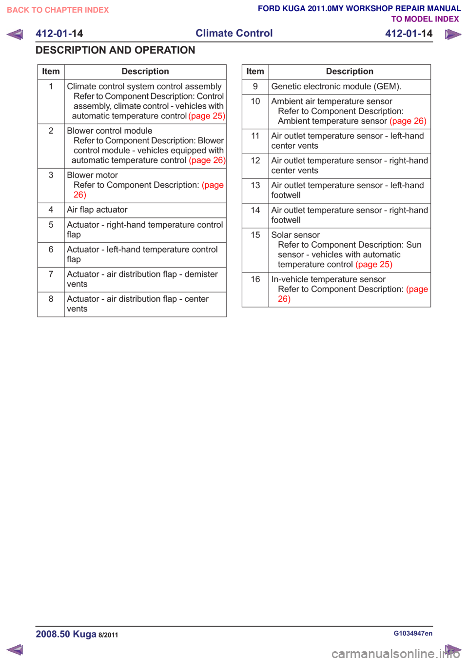
Description
Item
Climate control system control assemblyRefer to Component Description: Control
assembly, climate control - vehicles with
automatictemperaturecontrol (page25)
1
Blower control moduleRefer to Component Description: Blower
control module - vehicles equipped with
automatictemperaturecontrol(page26)
2
Blower motorRefertoComponentDescription:(page
26)
3
Air flap actuator
4
Actuator - right-hand temperature control
flap
5
Actuator - left-hand temperature control
flap
6
Actuator - air distribution flap - demister
vents
7
Actuator - air distribution flap - center
vents
8Description
Item
Genetic electronic module (GEM).
9
Ambient air temperature sensorRefer to Component Description:
Ambienttemperaturesensor(page26)
10
Air outlet temperature sensor - left-hand
center vents
11
Air outlet temperature sensor - right-hand
center vents
12
Air outlet temperature sensor - left-hand
footwell
13
Air outlet temperature sensor - right-hand
footwell
14
Solar sensorRefer to Component Description: Sun
sensor - vehicles with automatic
temperaturecontrol(page25)
15
In-vehicle temperature sensorRefertoComponentDescription:(page
26)
16
G1034947en2008.50 Kuga8/2011
412-01-
14
Climate Control
412-01- 14
DESCRIPTION AND OPERATION
TO MODEL INDEX
BACK TO CHAPTER INDEX
FORD KUGA 2011.0MY WORKSHOP REPAIR MANUAL
Page 2043 of 2057
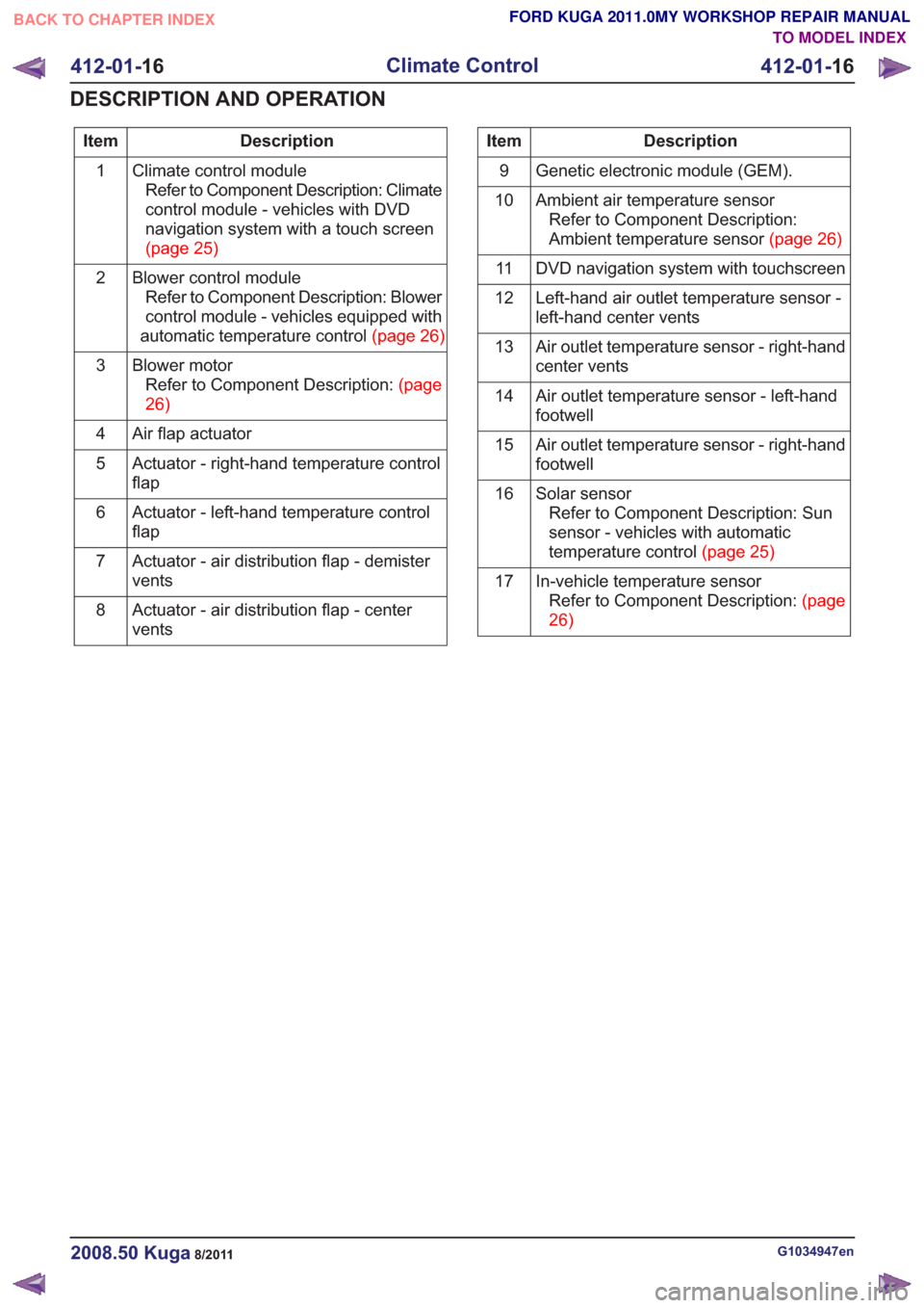
Description
Item
Climate control moduleRefer to Component Description: Climate
control module - vehicles with DVD
navigation system with a touch screen
(page25)
1
Blower control moduleRefer to Component Description: Blower
control module - vehicles equipped with
automatictemperaturecontrol(page26)
2
Blower motorRefertoComponentDescription:(page
26)
3
Air flap actuator
4
Actuator - right-hand temperature control
flap
5
Actuator - left-hand temperature control
flap
6
Actuator - air distribution flap - demister
vents
7
Actuator - air distribution flap - center
vents
8Description
Item
Genetic electronic module (GEM).
9
Ambient air temperature sensorRefer to Component Description:
Ambienttemperaturesensor(page26)
10
DVD navigation system with touchscreen
11
Left-hand air outlet temperature sensor -
left-hand center vents
12
Air outlet temperature sensor - right-hand
center vents
13
Air outlet temperature sensor - left-hand
footwell
14
Air outlet temperature sensor - right-hand
footwell
15
Solar sensorRefer to Component Description: Sun
sensor - vehicles with automatic
temperaturecontrol(page25)
16
In-vehicle temperature sensorRefertoComponentDescription:(page
26)
17
G1034947en2008.50 Kuga8/2011
412-01-
16
Climate Control
412-01- 16
DESCRIPTION AND OPERATION
TO MODEL INDEX
BACK TO CHAPTER INDEX
FORD KUGA 2011.0MY WORKSHOP REPAIR MANUAL
Page 2053 of 2057
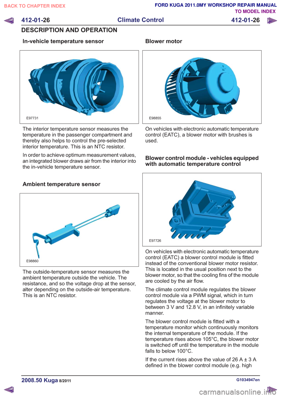
In-vehicle temperature sensor
E97731
The interior temperature sensor measures the
temperature in the passenger compartment and
thereby also helps to control the pre-selected
interior temperature. This is an NTC resistor.
In order to achieve optimum measurement values,
an integrated blower draws air from the interior into
the in-vehicle temperature sensor.
Ambient temperature sensor
E98860
The outside-temperature sensor measures the
ambient temperature outside the vehicle. The
resistance, and so the voltage drop at the sensor,
alter depending on the outside-air temperature.
This is an NTC resistor.
Blower motor
E98855
On vehicles with electronic automatic temperature
control (EATC), a blower motor with brushes is
used.
Blower control module - vehicles equipped
with automatic temperature control
E97726
On vehicles with electronic automatic temperature
control (EATC) a blower control module is fitted
instead of the conventional blower motor resistor.
This is located in the usual position next to the
blower motor, so that the cooling fins of the module
are cooled by the air flow.
The climate control module regulates the blower
control module via a PWM signal, which in turn
regulates the voltage at the blower motor to
between 3 V and 12.8 V, in an infinitely variable
manner.
The blower control module is fitted with a
temperature monitor which continuously monitors
the internal temperature of the module. If the
temperature rises above 105°C, the blower motor
is switched off until the temperature in the module
falls to below 100°C.
If the current rises above the value of 26 A ± 3 A
defined in the blower control module (e.g. high
G1034947en2008.50 Kuga8/2011
412-01-26
Climate Control
412-01- 26
DESCRIPTION AND OPERATION
TO MODEL INDEX
BACK TO CHAPTER INDEX
FORD KUGA 2011.0MY WORKSHOP REPAIR MANUAL