Throttle FORD KUGA 2011 1.G Workshop Manual
[x] Cancel search | Manufacturer: FORD, Model Year: 2011, Model line: KUGA, Model: FORD KUGA 2011 1.GPages: 2057
Page 80 of 2057
Noise Conditions
• Gear noise is typically a howling or whining dueto gear damage or incorrect bearing preload. It
can occur at various speeds and driving
conditions, or it can be continuous.
• Chuckle is a particular rattling noise that sounds like a stick against the spokes of a spinning
bicycle wheel. It occurs while decelerating from
64 km/h (40 mph) and can usually be heard all
the way to a stop. The frequency varies with
vehicle speed.
• Knock is very similar to chuckle, though it may be louder and occurs on acceleration or
deceleration. The teardown will disclose what
has to be corrected.
Clicking, popping or grinding noises may be caused
by the following:
• worn, damaged or incorrectly installed wheel bearing, suspension or brake component.
Check and rule out tires, exhaust and trim items
before disassembling the transmission to diagnose
and correct gear noise.
The noises described under Road Test usually
have specific causes that can be diagnosed by
observation as the unit is disassembled. The initial
clues are the type of noise heard on the road test
and driving conditions.
Vibration Conditions
Vibration at highway speeds may be caused by
the following:
• out-of-balance front or rear wheels.
• out-of-round tires.
Shudder or vibration during acceleration may be
caused by the following:
• damaged powertrain/drivetrain mounts.
• excessively high constant velocity (CV) joint operating angles caused by incorrect ride height.
Check ride height, verify correct spring rate and
check items under inoperative conditions.
Road Test
A gear-driven unit will produce a certain amount
of noise. Some noise is acceptable and may be
audible at certain speeds or under various driving
conditions, as on a newly paved asphalt road. The slight noise is in no way detrimental and must be
considered normal.
The road test and customer interview (if available)
provide information needed to identify the condition
and give direction to the correct starting point for
diagnosis.
1. Make notes throughout the diagnosis routine.
Make sure to write down even the smallest bit
of information, because it may turn out to be the
most important.
2. Do not touch anything until a road test and a thorough visual inspection of the vehicle have
been carried out. Leave the tire pressures and
vehicle load just where they were when the
condition was first observed. Adjusting tire
pressures, vehicle load or making other
adjustments may reduce the condition(s)
intensity to a point where it cannot be identified
clearly. It may also inject something new into
the system, preventing correct diagnosis.
3. Make a visual inspection as part of the preliminary diagnosis routine, writing down
anything that does not look right. Note tire
pressures, but do not adjust them yet. Note
leaking fluids, loose nuts and bolts, or bright
spots where components may be rubbing
against each other. Check the load space for
unusual loads.
4. Road test the vehicle and define the condition by reproducing it several times during the road
test.
5. Carry out the Road Test Quick Checks as soon as the condition is reproduced. This will identify
the correct diagnostic procedure. Carry out the
Road Test Quick Checks more than once to
verify they are providing a valid result.
Remember, the Road Test Quick Checks may
not tell where the concern is, but they will tell
where it is not.
Road Test Quick Checks
1. 24-80 km/h (15-50 mph): with light acceleration,a moaning noise is heard and possibly a
vibration felt in the front floor panel. It is usually
worse at a particular engine speed and at a
particular throttle setting during acceleration at
that speed. It may also produce a moaning
sound, depending on what component is
causing it. REFER to Tip-in Moan in the
Driveline Noise and Vibration Symptom Chart.
2. Acceleration/Deceleration: With slow acceleration and deceleration, a shake is
G37349en2008.50 Kuga8/2011
100-04- 3
Noise, Vibration and Harshness
100-04- 3
DIAGNOSIS AND TESTING
TO MODEL INDEX
BACK TO CHAPTER INDEX
FORD KUGA 2011.0MY WORKSHOP REPAIR MANUAL
Page 81 of 2057
Noise, Vibration and Harshness (NVH)
Inspection and Verification
1. Verify the customer concern.
2. Visually inspect for obvious signs of mechanicalor electrical damage.
3. If an obvious cause for an observed or reported concern is found, correct the cause (if possible)
before proceeding to the next step.
4. If the concern is not visually evident, verify the symptom and REFER to the Symptom Chart.
How to Use this Diagnostic Procedure
Section
• Noise, vibration and harshness (NVH) concernshave become more important as vehicles have
become more sensitive to these vibrations. This
section is designed to aid in identifying these
concerns.
• The section provides diagnostic procedures based on symptom. If the condition occurs at
high speed, for instance, the most likely place
to start is under Shake and Vibration While
Driving.
• The road test procedure will tell how to sort the conditions into categories and how to tell a
vibration from a shake.
• A series of Road Test Quick Checks are provided to make sure that a cause is either
pinpointed or eliminated.
• Name the condition, proceed to the appropriate section and locate the correct diagnosis. When
the condition is identified, the job is partly done.
• Follow the diagnostic procedure as outlined.
• Quick Checks are described within the step, while more involved tests and adjustments are
outlined in General Procedures.
• Always follow each step exactly and make notes to recall important findings later.
Customer Interview
The road test and customer interview (if available)
provide information that will help identify the
concern and will provide direction to the correct
starting point for diagnosis.
Identify the Condition
NVH usually occur in four areas:
• tires
• engine accessories
• suspension
• driveline
It is important, therefore, that an NVH concern be
isolated into its specific area(s) as soon as
possible. The easiest and quickest way to do this
is to carry out the Road Test as outlined. To assist
in the diagnosis and testing procedure(s), use a
suitable approved NVH diagnosis tester.
Noise Diagnostic Procedure
Non-Axle Noise
The five most common sources of non-axle noise
are exhaust, tires, roof racks, trim panels and
transmission.
Therefore, make sure that none of the following
conditions are the cause of the noise before
proceeding with a driveline teardown and
diagnosis.
• In certain conditions, the pitch of the exhaustmay sound very much like gear noise. At other
times, it can be mistaken for a wheel bearing
rumble.
• Tires, especially snow tires, can have a high pitched tread whine or roar, similar to gear
noise. Radial tires may have this characteristic.
Also, any non-standard tire with an unusual
tread construction may emit a roar or whine
noise.
• Trim panels can also cause whistling or whining noise.
• Clunk may be a metallic noise heard when the automatic transaxle is engaged in "R"
(REVERSE) or "D" (DRIVE) or it may occur
when the throttle is applied or released. It is
caused by backlash somewhere in the driveline.
• Bearing rumble sounds like marbles being tumbled. This condition is usually caused by a
damaged wheel bearing.
G37349en2008.50 Kuga8/2011
100-04- 2
Noise, Vibration and Harshness
100-04- 2
DIAGNOSIS AND TESTING
TO MODEL INDEX
BACK TO CHAPTER INDEX
FORD KUGA 2011.0MY WORKSHOP REPAIR MANUAL
Page 1252 of 2057
General overview
Haldex clutches of the 3rd and 4th generations are
used in the Ford Kuga.
The development of the third generation Haldex
clutch represents a big step forward in modern
all-wheel technology. The Haldex clutch is
electro-hydraulically controlled. Additional
information is taken into consideration during
control tasks via the all-wheel drive control unit.
Slip alone is no longer decisive for the distribution
of the propulsive forces; the vehicle's driving
dynamics are also taken into consideration. The
control unit accesses the driving-related data via
the data bus. With this data, the control unit has
all the essential information about speed, cornering,
coasting or traction operation, and can optimally
react to every driving situation.
Compared with the previous generation, the 4th
generation Haldex clutches operate with higher
pressure and achieve shorter response times when
distributing the drive forces.
Advantages of the Haldex clutch:
• Permanent all-wheel drive withelectronically-controlled multi-plate clutch
• Fast response
• No straining when parking and manoeuvring
• Compatible with different tyres (e.g. emergency spare wheel)
• Fully combinable with driving dynamic control systems
The driveshaft is connected to the input shaft of
the Haldex clutch. Within the Haldex clutch, the
input shaft is separated from the output shaft to
the rear axle differential by means of a multi-plate
clutch. Torque is only transmitted to the rear axle
differential when the plate assembly of the Haldex
clutch is closed.
The multi-plate clutch is electro-hydraulically
controlled via the all-wheel drive control unit. For
ecological driving, the torque to the rear axle is reduced to a minimum up to a throttle position of
approx. 50%. A prerequisite for this is that there is
no difference in speed in the Haldex clutch between
the input and output shafts.
Operation
E100645
16
3
25
4
Description
Item
Output shaft
1
Working piston
2
Plates
3
Ring piston pump
4
Control Valve
5
Input shaft
6
Within the Haldex clutch is a plate assembly and
a so-called ring piston pump with a pump plunger
and a working piston.
Fluid supply is started if there is a speed difference
between the input and output shafts.
This fluid pressure is transmitted to the working
piston and in this way the plate assembly is
compressed.
Design of the 3rd generation Haldex
clutch
G1076981en2008.50 Kuga8/2011
205-02- 7
Rear Drive Axle/Differential
205-02- 7
DESCRIPTION AND OPERATION
TO MODEL INDEX
BACK TO CHAPTER INDEX
FORD KUGA 2011.0MY WORKSHOP REPAIR MANUAL
Page 1526 of 2057
Measure the compression pressure
(Engine - 2.5L Duratec-ST (VI5))
TIE44608
1. Remove the central junction box (CJB) cover.
TIE44609
2. Open the CJB and remove the fuel pump relay.
3. NOTE: The engine will start, run for a fewseconds and then stop.
Start the engine.
4. Remove the ignition coil-on-plug.
REFER to: Ignition Coil-On-Plug (303-07 Engine
Ignition - 2.5L Duratec (147kW/200PS) - VI5,
Removal and Installation). 5. Connect the battery ground cable.
REFER to: Battery Disconnect and Connect
(414-01 Battery, Mounting and Cables,
General Procedures).
E68679
x5
6. Using Special Tool 303-499, remove the spark plugs.
E68434
NOTE: Operate the starter motor with wide open
throttle until the pointer on the measuring device
stops rising.
7. Carry out the measurement in accordance with the instructions supplied with the measuring
device on every cylinder using a suitable
compression pressure recorder with a suitable
adapter.
E68680
28 Nm
8. Using Special Tool 303-499, install the sparkplugs.
G1055128en2008.50 Kuga8/2011
303-00- 10
Engine System - General Information
303-00- 10
DIAGNOSIS AND TESTING
TO MODEL INDEX
BACK TO CHAPTER INDEX
FORD KUGA 2011.0MY WORKSHOP REPAIR MANUAL
Page 1549 of 2057
Engine – System Operation and Component Description
System Operation
The variable camshaft timing occurs
electro-hydraulically and individually for both
camshafts.
The camshaft adjusters work according to the vane
cell principle and have an adjustment range of 52°
crank angle on the intake side and 47° crank angle
on the exhaust side. On starting the engine and
during idling, both camshafts are mechanically
locked in their starting positions. The exhaust
camshaft is in the early position and the intake
camshaft is in the late position. The camshaftadjuster on the exhaust side has a torsion spring
which compensates the camshaft drive torque.
This ensures that the assembly can return to the
starting position under all operating conditions and
when the engine is turned off.
Internal exhaust gas recirculation can be realized
through continuous adjustment of the timings. This
results in better fuel consumption and more
favorable combustion temperatures which produce
less pollutants. This means that pollutant level IV
can be adhered to with a 3-way catalytic converter.
The variable timings also make it possible to
optimize performance with wide open throttle.
G1032416en2008.50 Kuga8/2011
303-01-
16
Engine— 2.5L Duratec (147kW/200PS) - VI5303-01-
16
DESCRIPTION AND OPERATION
TO MODEL INDEX
BACK TO CHAPTER INDEX
FORD KUGA 2011.0MY WORKSHOP REPAIR MANUAL
Page 1692 of 2057
SECTION 303-04A Fuel Charging and Controls— 2.5L Duratec
(147kW/200PS) - VI5
VEHICLE APPLICATION: 2008.50 Kuga
PA G E
CONTENTS
DESCRIPTION AND OPERATION
303-04A-2
Fuel Charging and Controls ........................................................................\
........................
DIAGNOSIS AND TESTING 303-04A-4
Fuel Charging and Controls ........................................................................\
........................
303-04A-4
Inspection and Verification ........................................................................\
..........................
303-04A-4
Symptom Chart ........................................................................\
...........................................
REMOVAL AND INSTALLATION 303-04A-22
Fuel Injectors ........................................................................\
..............................................
303-04A-23
(23 198 0)
Throttle Body ........................................................................\
..........................
303-04A-24
Fuel Rail ........................................................................\
......................................................
303-04A- 1
Fuel Charging and Controls
— 2.5L Duratec (147kW/200PS) -
VI5
303-04A- 1
.
TO MODEL INDEX
BACK TO CHAPTER INDEX
FORD KUGA 2011.0MY WORKSHOP REPAIR MANUAL
Page 1694 of 2057
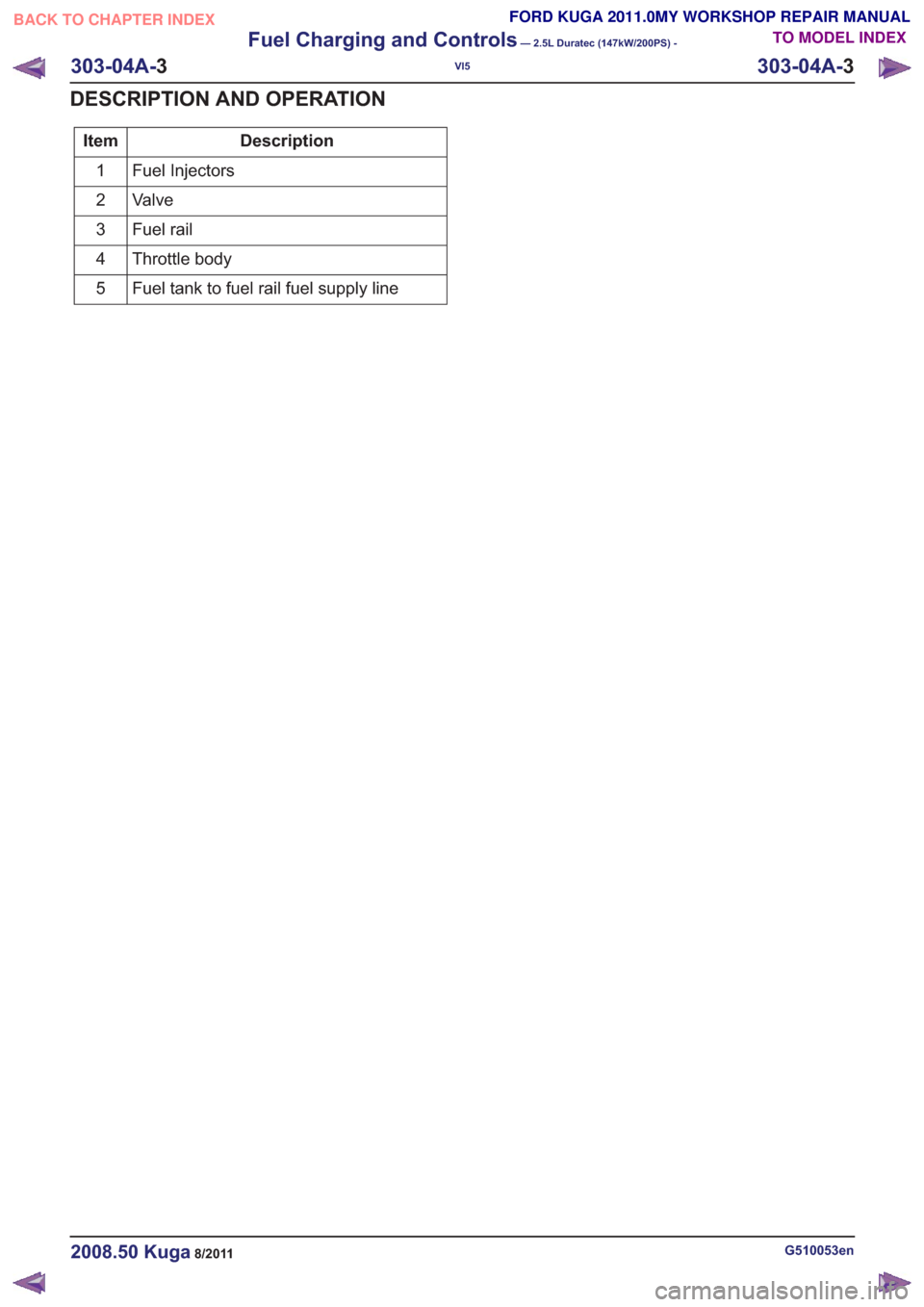
Description
Item
Fuel Injectors
1
Valve
2
Fuel rail
3
Throttle body
4
Fuel tank to fuel rail fuel supply line
5
G510053en2008.50 Kuga8/2011
303-04A- 3
Fuel Charging and Controls
— 2.5L Duratec (147kW/200PS) -
VI5
303-04A- 3
DESCRIPTION AND OPERATION
TO MODEL INDEX
BACK TO CHAPTER INDEX
FORD KUGA 2011.0MY WORKSHOP REPAIR MANUAL
Page 1714 of 2057
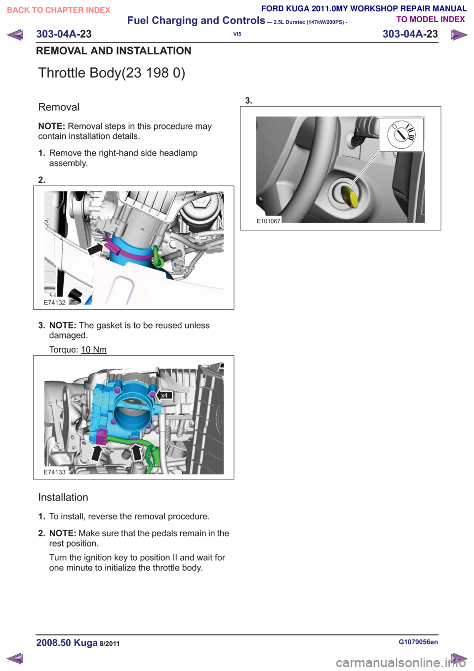
Throttle Body(23 198 0)
Removal
NOTE:Removal steps in this procedure may
contain installation details.
1. Remove the right-hand side headlamp
assembly.
2.
E74132
3. NOTE: The gasket is to be reused unless
damaged.
Torque: 10
Nm
E74133
x4
Installation
1. To install, reverse the removal procedure.
2. NOTE: Make sure that the pedals remain in the
rest position.
Turn the ignition key to position II and wait for
one minute to initialize the throttle body. 3.
E101067
G1079056en2008.50 Kuga8/2011
303-04A-
23
Fuel Charging and Controls
— 2.5L Duratec (147kW/200PS) -
VI5
303-04A- 23
REMOVAL AND INSTALLATION
TO MODEL INDEX
BACK TO CHAPTER INDEX
FORD KUGA 2011.0MY WORKSHOP REPAIR MANUAL
Page 1722 of 2057
Description
Item
PWM (pulse width modulation) signal
Comments:from PCM (powertrain control module)
5
Atmospheric pressure
6
Turbocharger boost pressure.
7
from air filter
8
Intake air
9Description
Item
Recirculated air valveRefertoComponentDescription:(page
7)
10
Vacuum line, recirculated air valve
11
to intake manifold
12
Throttle plate
13
Compressor
14
Turbine
15
System Operation
Turbocharger(s)
The TC consists of a turbine and a compressor.
The turbine is driven by the exhaust gas flow. A
common shaft drives the compressor and this then
compresses the intake air.
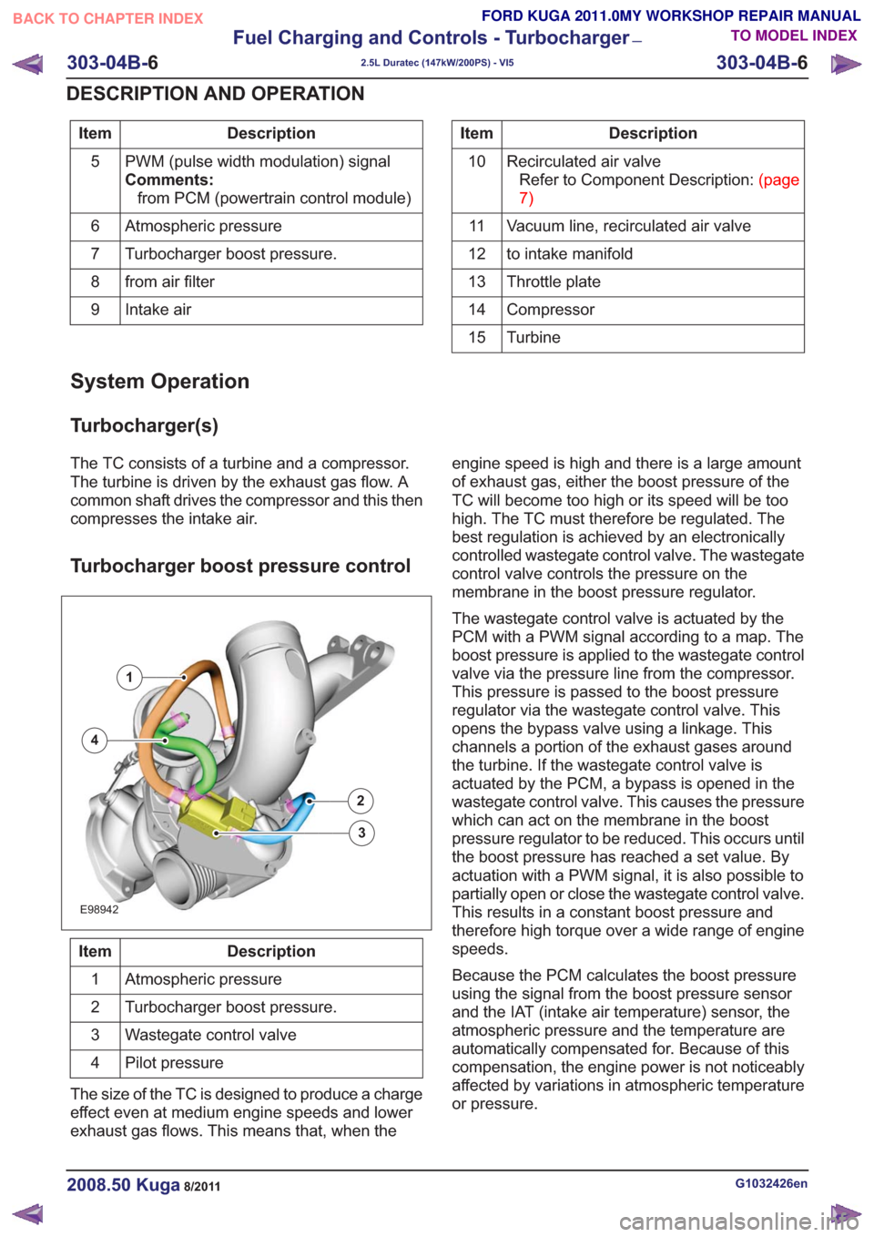
Turbocharger boost pressure control
E98942
1
2
3
4
Description
Item
Atmospheric pressure
1
Turbocharger boost pressure.
2
Wastegate control valve
3
Pilot pressure
4
The size of the TC is designed to produce a charge
effect even at medium engine speeds and lower
exhaust gas flows. This means that, when the engine speed is high and there is a large amount
of exhaust gas, either the boost pressure of the
TC will become too high or its speed will be too
high. The TC must therefore be regulated. The
best regulation is achieved by an electronically
controlled wastegate control valve. The wastegate
control valve controls the pressure on the
membrane in the boost pressure regulator.
The wastegate control valve is actuated by the
PCM with a PWM signal according to a map. The
boost pressure is applied to the wastegate control
valve via the pressure line from the compressor.
This pressure is passed to the boost pressure
regulator via the wastegate control valve. This
opens the bypass valve using a linkage. This
channels a portion of the exhaust gases around
the turbine. If the wastegate control valve is
actuated by the PCM, a bypass is opened in the
wastegate control valve. This causes the pressure
which can act on the membrane in the boost
pressure regulator to be reduced. This occurs until
the boost pressure has reached a set value. By
actuation with a PWM signal, it is also possible to
partially open or close the wastegate control valve.
This results in a constant boost pressure and
therefore high torque over a wide range of engine
speeds.
Because the PCM calculates the boost pressure
using the signal from the boost pressure sensor
and the IAT (intake air temperature) sensor, the
atmospheric pressure and the temperature are
automatically compensated for. Because of this
compensation, the engine power is not noticeably
affected by variations in atmospheric temperature
or pressure.
G1032426en2008.50 Kuga8/2011
303-04B-
6
Fuel Charging and Controls - Turbocharger
—
2.5L Duratec (147kW/200PS) - VI5
303-04B- 6
DESCRIPTION AND OPERATION
TO MODEL INDEX
BACK TO CHAPTER INDEX
FORD KUGA 2011.0MY WORKSHOP REPAIR MANUAL
Page 1723 of 2057
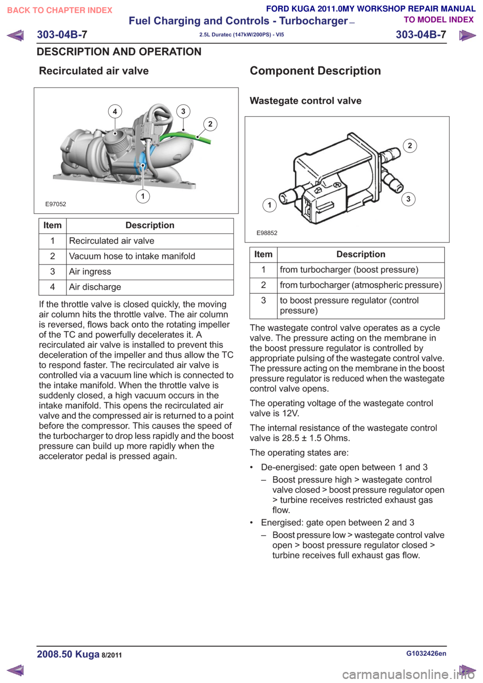
Recirculated air valve
E97052
43
2
1
Description
Item
Recirculated air valve
1
Vacuum hose to intake manifold
2
Air ingress
3
Air discharge
4
If the throttle valve is closed quickly, the moving
air column hits the throttle valve. The air column
is reversed, flows back onto the rotating impeller
of the TC and powerfully decelerates it. A
recirculated air valve is installed to prevent this
deceleration of the impeller and thus allow the TC
to respond faster. The recirculated air valve is
controlled via a vacuum line which is connected to
the intake manifold. When the throttle valve is
suddenly closed, a high vacuum occurs in the
intake manifold. This opens the recirculated air
valve and the compressed air is returned to a point
before the compressor. This causes the speed of
the turbocharger to drop less rapidly and the boost
pressure can build up more rapidly when the
accelerator pedal is pressed again.
Component Description
Wastegate control valve
1
2
3
E98852
Description
Item
from turbocharger (boost pressure)
1
from turbocharger (atmospheric pressure)
2
to boost pressure regulator (control
pressure)
3
The wastegate control valve operates as a cycle
valve. The pressure acting on the membrane in
the boost pressure regulator is controlled by
appropriate pulsing of the wastegate control valve.
The pressure acting on the membrane in the boost
pressure regulator is reduced when the wastegate
control valve opens.
The operating voltage of the wastegate control
valve is 12V.
The internal resistance of the wastegate control
valve is 28.5 ± 1.5 Ohms.
The operating states are:
• De-energised: gate open between 1 and 3 – Boost pressure high > wastegate controlvalve closed > boost pressure regulator open
> turbine receives restricted exhaust gas
flow.
• Energised: gate open between 2 and 3 – Boost pressure low > wastegate control valveopen > boost pressure regulator closed >
turbine receives full exhaust gas flow.
G1032426en2008.50 Kuga8/2011
303-04B- 7
Fuel Charging and Controls - Turbocharger
—
2.5L Duratec (147kW/200PS) - VI5
303-04B- 7
DESCRIPTION AND OPERATION
TO MODEL INDEX
BACK TO CHAPTER INDEX
FORD KUGA 2011.0MY WORKSHOP REPAIR MANUAL