egr valve FORD KUGA 2011 1.G Workshop Manual
[x] Cancel search | Manufacturer: FORD, Model Year: 2011, Model line: KUGA, Model: FORD KUGA 2011 1.GPages: 2057
Page 50 of 2057
foams should be conducted with extraction
ventilation. See also the vehicle Body Repair
Manual.
Freon
SeeAir Conditioning Refrigerant.
Fuels
See also, Fire, Legal Aspects, Chemicalsand
Solvents.
Avoid skin contact with fuel where possible. Should
contact occur, wash the affected skin with soap
and water.
Gasoline (Petrol)
Highly flammable - observe No Smoking policy.
For additional information, refer to: Petrol and
Petrol-Ethanol Fuel Systems Health and Safety
Precautions (100-00 General Information,
Description and Operation).
Gas-oil (Diesel Fuel)
Kerosene (Paraffin)
Used also as heating fuel, solvent and cleaning
agent.
Flammable - observe No Smoking policy.
Irritation of the mouth and throat may result from
swallowing. The main hazard from swallowing
arises if liquid aspiration into the lungs occurs.
Liquid contact dries the skin and can cause
irritation or dermatitis. Splashes in the eye may be
slightly irritating.
In normal circumstances the low volatility does not
give rise to harmful vapors. Exposure to mists and
vapors from kerosene at elevated temperature
should be avoided (mists may arise in dewaxing).
Avoid skin and eye contact and make sure there
is adequate ventilation.
Gas Cylinders
See also Fire. Gases such as oxygen, acetylene, argon and
propane are normally stored in cylinders at
pressures of up to 138 bar (2000 psi) and great
care should be taken in handling these cylinders
to avoid mechanical damage to them or to the valve
gear attached. The contents of each cylinder
should be clearly identified by appropriate
markings.
Cylinders should be stored in well-ventilated
enclosures, and protected from ice and snow, or
direct sunlight. Fuel gases, for example acetylene
and propane, should not be stored in close
proximity to oxygen cylinders.
Care should be exercised to prevent leaks from
gas cylinders and lines, and to avoid sources of
ignition.
Only trained personnel should undertake work
involving gas cylinders.
Gases
See
Gas Cylinders.
Gaskets (Fluoroelastomer)
SeeViton.
General Workshop Tools and
Equipment
It is essential that all tools and equipment are
maintained in good condition and that the correct
safety equipment is used where required.
Never use tools or equipment for any purpose other
than that for which they were designed. Never
overload equipment such as hoists, jacks, axle and
chassis stands or lifting slings. Damage caused by
overloading is not always immediately apparent
and may result in a fatal failure the next time that
the equipment is used.
Do not use damaged or defective tools or
equipment, particularly high-speed equipment such
as grinding wheels. A damaged grinding wheel can
disintegrate without warning and cause serious
injury.
Wear suitable eye protection when using grinding,
chiseling or sand blasting equipment.
Wear a suitable breathing mask when using
abrasive blasting equipment, working with
asbestos-based materials or using spraying
equipment.
G566527en2008.50 Kuga8/2011
100-00- 47
General Information
100-00- 47
DESCRIPTION AND OPERATION
TO MODEL INDEX
BACK TO CHAPTER INDEX
FORD KUGA 2011.0MY WORKSHOP REPAIR MANUAL
Page 87 of 2057
Action
Possible Sources
Symptom
CHECK the installation and
potential damage of the floor
seal.
Floor seal.
NOTE:
Engine speed at idle
turning the steering wheel slowly
lock to lock.
Power steering system hiss noise
– a high frequency, continuous
rush or swish noise like escaping
air from a balloon. Hiss occurs
while turning between the
steering lock stops, all steering
angles. Noise does not change
with engine rpm and is worse at
high operating temperatures. Certain amount of noise level
acceptable, not a safety critical
item.
Power steering gear valve
design.
Certain amount of noise level
acceptable, not a safety critical
item.
Power steering system hydraulic
design.
Certain amount of noise level
acceptable, not a safety critical
item.
Power steering pump pressure
relief valve.
NOTE:
Engine speed at idle
holding the steering wheel
against a steering lock for three
seconds. Do not hold for more
than five seconds.
Power steering system hiss noise
– a continuous noise like
escaping air occurs while holding
the steering against a steering
lock stop.
Power Steering Lock Stop Impact Knock
Noise
Test Condition
Listen for steering knock noise with the engine
speed at idle in the following test conditions (noise
also apparent with engine off). 1. Turn the steering wheel to the left-hand and
right-hand steering locks and listen for the
impact noise.
Action
Possible Sources
Symptom
Certain amount of noise level
acceptable, not a safety critical
item.
Power steering gear mechanical
noise, metal to metal at end of
steering travel.
Power steering system knock
noise – a heavy loud sound like
a knock on a door that occurs in
parking condition when hitting the
lock stop.
Power Steering Mechanical Knock Noise
(PAS off)
Test Condition
Listen for steering knock noise with the engine off
in the following test conditions (no power assist). 1. Turn the steering wheel 90 degrees to the right,
hold and then quickly release.
2. Turn the steering wheel 90 degrees to the left, hold and then quickly release.
G37349en2008.50 Kuga8/2011
100-04- 9
Noise, Vibration and Harshness
100-04- 9
DIAGNOSIS AND TESTING
TO MODEL INDEX
BACK TO CHAPTER INDEX
FORD KUGA 2011.0MY WORKSHOP REPAIR MANUAL
Page 1254 of 2057
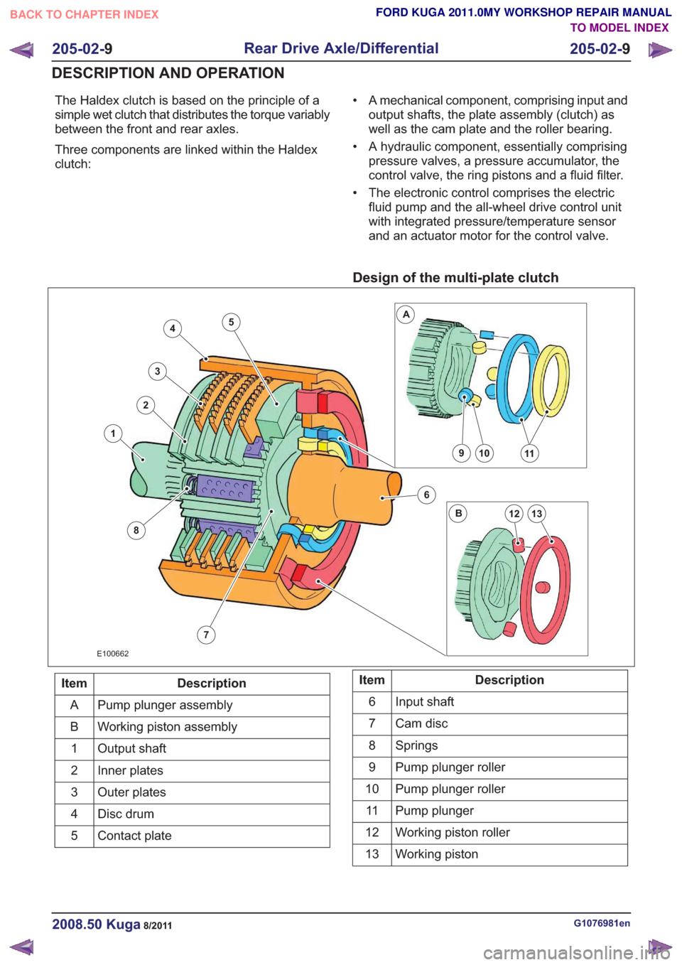
The Haldex clutch is based on the principle of a
simple wet clutch that distributes the torque variably
between the front and rear axles.
Three components are linked within the Haldex
clutch:• A mechanical component, comprising input and
output shafts, the plate assembly (clutch) as
well as the cam plate and the roller bearing.
• A hydraulic component, essentially comprising pressure valves, a pressure accumulator, the
control valve, the ring pistons and a fluid filter.
• The electronic control comprises the electric fluid pump and the all-wheel drive control unit
with integrated pressure/temperature sensor
and an actuator motor for the control valve.
Design of the multi-plate clutch
7
4
3
2
8
1
6
10911
13
A
B12
5
E100662
Description
Item
Pump plunger assembly
A
Working piston assembly
B
Output shaft
1
Inner plates
2
Outer plates
3
Disc drum
4
Contact plate
5Description
Item
Input shaft
6
Cam disc
7
Springs
8
Pump plunger roller
9
Pump plunger roller
10
Pump plunger
11
Working piston roller
12
Working piston
13
G1076981en2008.50 Kuga8/2011
205-02- 9
Rear Drive Axle/Differential
205-02- 9
DESCRIPTION AND OPERATION
TO MODEL INDEX
BACK TO CHAPTER INDEX
FORD KUGA 2011.0MY WORKSHOP REPAIR MANUAL
Page 1467 of 2057
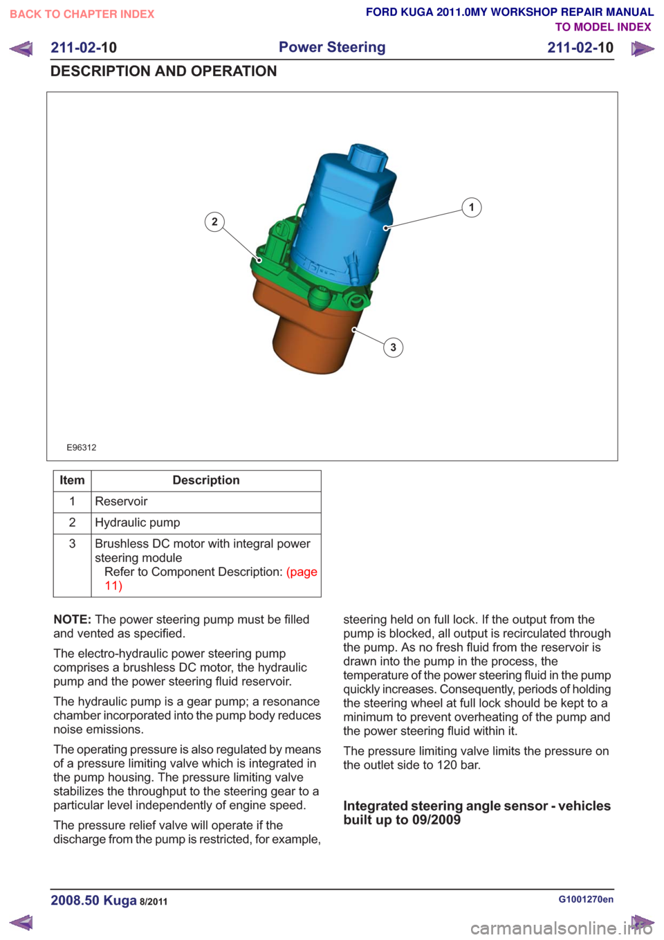
E96312
1
2
3
Description
Item
Reservoir
1
Hydraulic pump
2
Brushless DC motor with integral power
steering moduleRefertoComponentDescription:(page
11)
3
NOTE: The power steering pump must be filled
and vented as specified.
The electro-hydraulic power steering pump
comprises a brushless DC motor, the hydraulic
pump and the power steering fluid reservoir.
The hydraulic pump is a gear pump; a resonance
chamber incorporated into the pump body reduces
noise emissions.
The operating pressure is also regulated by means
of a pressure limiting valve which is integrated in
the pump housing. The pressure limiting valve
stabilizes the throughput to the steering gear to a
particular level independently of engine speed.
The pressure relief valve will operate if the
discharge from the pump is restricted, for example, steering held on full lock. If the output from the
pump is blocked, all output is recirculated through
the pump. As no fresh fluid from the reservoir is
drawn into the pump in the process, the
temperature of the power steering fluid in the pump
quickly increases. Consequently, periods of holding
the steering wheel at full lock should be kept to a
minimum to prevent overheating of the pump and
the power steering fluid within it.
The pressure limiting valve limits the pressure on
the outlet side to 120 bar.
Integrated steering angle sensor - vehicles
built up to 09/2009
G1001270en2008.50 Kuga8/2011
211-02-
10
Power Steering
211-02- 10
DESCRIPTION AND OPERATION
TO MODEL INDEX
BACK TO CHAPTER INDEX
FORD KUGA 2011.0MY WORKSHOP REPAIR MANUAL
Page 1528 of 2057
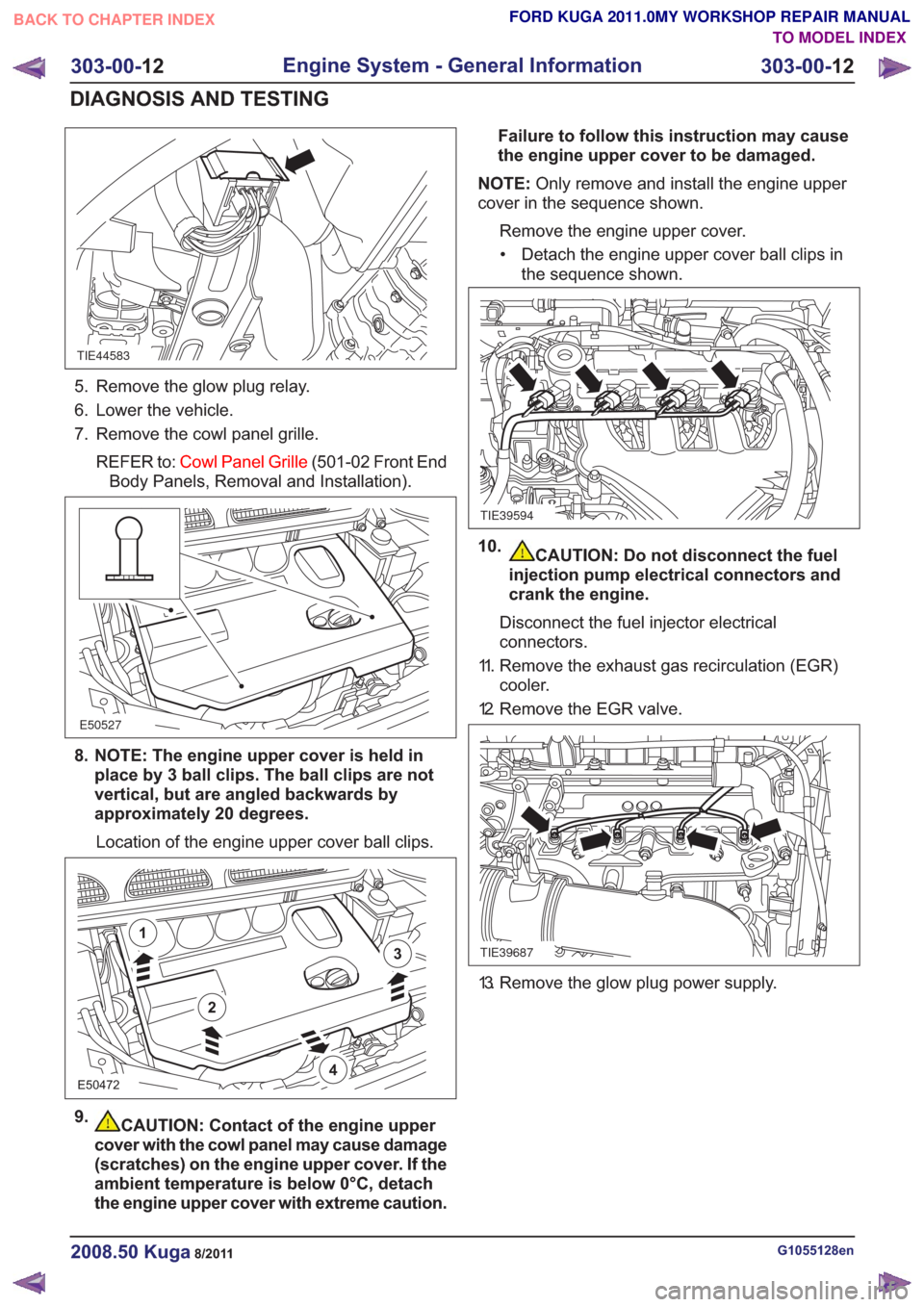
TIE44583
5. Remove the glow plug relay.
6. Lower the vehicle.
7. Remove the cowl panel grille.REFER to: Cowl Panel Grille (501-02 Front End
Body Panels, Removal and Installation).
E50527
8. NOTE: The engine upper cover is held in place by 3 ball clips. The ball clips are not
vertical, but are angled backwards by
approximately 20 degrees.
Location of the engine upper cover ball clips.
E50472
2
1
3
4
9.CAUTION: Contact of the engine upper
cover with the cowl panel may cause damage
(scratches) on the engine upper cover. If the
ambient temperature is below 0°C, detach
the engine upper cover with extreme caution. Failure to follow this instruction may cause
the engine upper cover to be damaged.
NOTE: Only remove and install the engine upper
cover in the sequence shown.
Remove the engine upper cover.• Detach the engine upper cover ball clips in the sequence shown.
TIE39594
10.CAUTION: Do not disconnect the fuel
injection pump electrical connectors and
crank the engine.
Disconnect the fuel injector electrical
connectors.
11. Remove the exhaust gas recirculation (EGR) cooler.
12. Remove the EGR valve.
TIE39687
13. Remove the glow plug power supply.
G1055128en2008.50 Kuga8/2011
303-00- 12
Engine System - General Information
303-00- 12
DIAGNOSIS AND TESTING
TO MODEL INDEX
BACK TO CHAPTER INDEX
FORD KUGA 2011.0MY WORKSHOP REPAIR MANUAL
Page 1529 of 2057
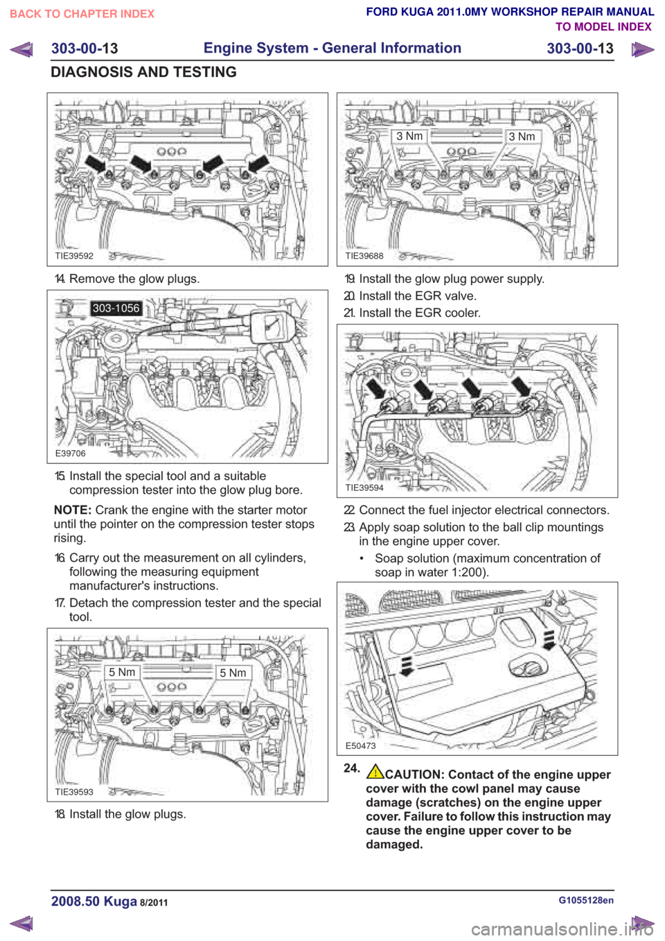
18. Install the glow plugs.
CAUTION: Contact of the engine upper
cover with the cowl panel may cause
damage (scratches) on the engine upper
cover. Failure to follow this instruction may
cause the engine upper cover to be
damaged.
G1055128en2008.50 Kuga8/2011
303-00- 13
Engine System - General Information
303-00- 13
DIAGNOSIS AND TESTING
FORD KUGA 2011.0MY WORKSHOP REPAIR MANUAL
TO MODEL INDEX
BACK TO CHAPTER INDEX
TIE39592TIE39688
E39706
303-1056
TIE39593
3Nm
TIE39594
E50473
3Nm
5Nm 5Nm
14. Remove the glow plugs.
15. Install the special tool and a suitable
compression tester into the glow plug bore.
NOTE: Crank the engine with the starter motor
until the pointer on the compression tester stops
rising.
16. Carry out the measurement on all cylinders, following the measuring equipment
manufacturer's instructions.
17. Detach the compression tester and the special tool.
19. Install the glow plug power supply.
20. Install the EGR valve.
21. Install the EGR cooler.
22. Connect the fuel injector electrical connectors.
23. Apply soap solution to the ball clip mountingsin the engine upper cover.
• Soap solution (maximum concentration of soap in water 1:200).
24.
Page 1537 of 2057
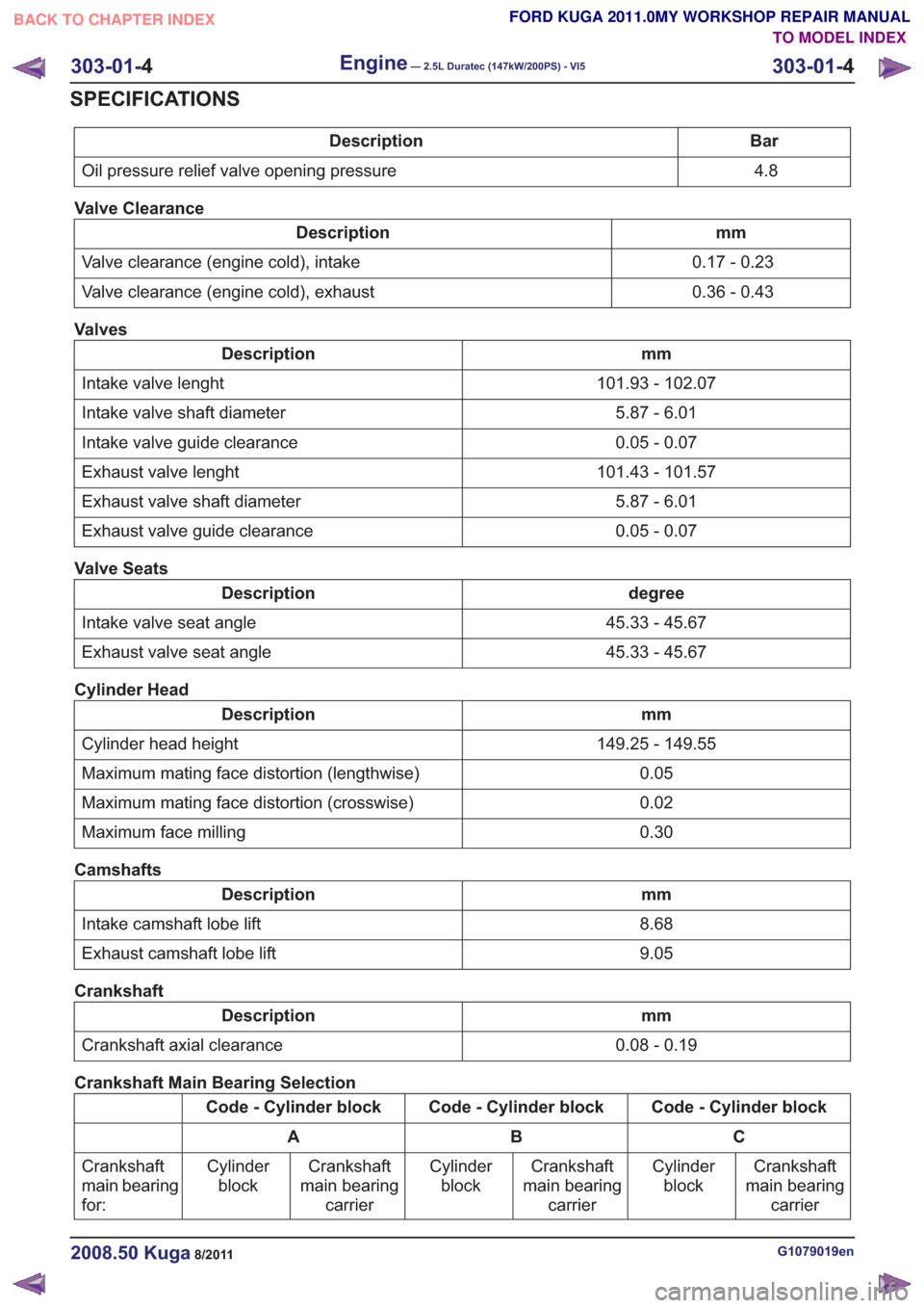
Bar
Description
4.8
Oil pressure relief valve opening pressure
Valve Clearance
mm
Description
0.17 - 0.23
Valve clearance (engine cold), intake
0.36 - 0.43
Valve clearance (engine cold), exhaust
Valves
mm
Description
101.93 - 102.07
Intake valve lenght
5.87 - 6.01
Intake valve shaft diameter
0.05 - 0.07
Intake valve guide clearance
101.43 - 101.57
Exhaust valve lenght
5.87 - 6.01
Exhaust valve shaft diameter
0.05 - 0.07
Exhaust valve guide clearance
Valve Seats
degree
Description
45.33 - 45.67
Intake valve seat angle
45.33 - 45.67
Exhaust valve seat angle
Cylinder Head
mm
Description
149.25 - 149.55
Cylinder head height
0.05
Maximum mating face distortion (lengthwise)
0.02
Maximum mating face distortion (crosswise)
0.30
Maximum face milling
Camshafts
mm
Description
8.68
Intake camshaft lobe lift
9.05
Exhaust camshaft lobe lift
Crankshaft
mm
Description
0.08 - 0.19
Crankshaft axial clearance
Crankshaft Main Bearing Selection
Code - Cylinder block
Code - Cylinder block
Code - Cylinder block
C
B
A
Crankshaft
main bearing carrier
Cylinder
block
Crankshaft
main bearing carrier
Cylinder
block
Crankshaft
main bearing carrier
Cylinder
block
Crankshaft
main bearing
for:
G1079019en2008.50 Kuga8/2011
303-01-
4
Engine— 2.5L Duratec (147kW/200PS) - VI5303-01-
4
SPECIFICATIONS
TO MODEL INDEX
BACK TO CHAPTER INDEX
FORD KUGA 2011.0MY WORKSHOP REPAIR MANUAL
Page 1543 of 2057
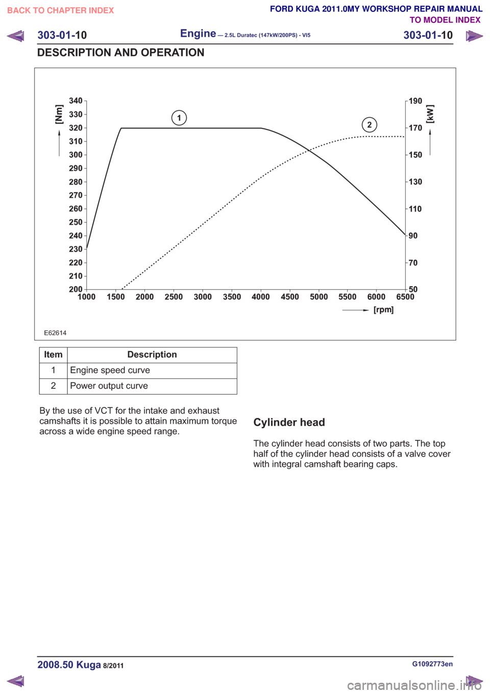
2
E62614
1
Description
Item
Engine speed curve
1
Power output curve
2
By the use of VCT for the intake and exhaust
camshafts it is possible to attain maximum torque
across a wide engine speed range.
Cylinder head
The cylinder head consists of two parts. The top
half of the cylinder head consists of a valve cover
with integral camshaft bearing caps.
G1092773en2008.50 Kuga8/2011
303-01- 10
Engine— 2.5L Duratec (147kW/200PS) - VI5303-01-
10
DESCRIPTION AND OPERATION
TO MODEL INDEX
BACK TO CHAPTER INDEX
FORD KUGA 2011.0MY WORKSHOP REPAIR MANUAL
Page 1675 of 2057
Engine Cooling
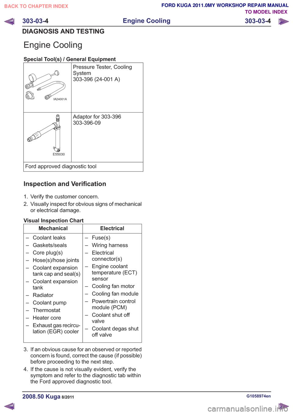
Special Tool(s) / General EquipmentPressure Tester, Cooling
System
303-396 (24-001 A)
IA24001A
Adaptor for 303-396
303-396-09
E55030
Ford approved diagnostic tool
Inspection and Verification
1. Verify the customer concern.
2. Visually inspect for obvious signs of mechanicalor electrical damage.
Visual Inspection Chart
Electrical
Mechanical
– Fuse(s)
– Wiring harness
– Electricalconnector(s)
– Engine coolant temperature (ECT)
sensor
– Cooling fan motor
– Cooling fan module
– Powertrain control module (PCM)
– Coolant shut off valve
– Coolant degas shut off valve
– Coolant leaks
– Gaskets/seals
– Core plug(s)
– Hose(s)/hose joints
– Coolant expansion
tank cap and seal(s)
– Coolant expansion tank
– Radiator
– Coolant pump
– Thermostat
– Heater core
– Exhaust gas recircu- lation (EGR) cooler
3. If an obvious cause for an observed or reported concern is found, correct the cause (if possible)
before proceeding to the next step.
4. If the cause is not visually evident, verify the symptom and refer to the diagnostic tab within
the Ford approved diagnostic tool.
G1058974en2008.50 Kuga8/2011
303-03- 4
Engine Cooling
303-03- 4
DIAGNOSIS AND TESTING
TO MODEL INDEX
BACK TO CHAPTER INDEX
FORD KUGA 2011.0MY WORKSHOP REPAIR MANUAL
Page 1720 of 2057
Turbocharger – Overview
Turbocharger(s)
CAUTION: Do not switch off the engine
while it is running at high speed. If the
engine is switched off while it is running
at high speed, the turbocharger will
continue to run after the engine oil
pressure has already dropped to zero. This
will cause premature wear in the
turbocharger bearings.
A TC consists of an exhaust turbine located in the
exhaust gas flow, this turbine is connected to a
compressor by a shaft. The turbine is made to
rotate by the exhaust gas flow from the engine and
thus drives the compressor. The compressor
increases the pressure in the engine intake tract
so that a greater mass of air enters the cylinder
during the intake stroke.
The turbine housing of the TC is integrated into the
exhaust manifold. This construction offers
thermodynamic advantages compared with the
usual construction, the maximum exhaust
temperature is up to 1050°C.
The maximum boost pressure is 0.65 bar.
The exhaust manifold is secured to the exhaust
side of the cylinder head with 12 self-locking nuts.
The exhaust manifold gasket is a multi-layer steel
gasket and cannot be reused. In order to
compensate for the thermal expansion of the
exhaust manifold, the flange of the TC is provided
with two grooves.
The TC and the exhaust manifold are joined by a
hose clip. The hose clip must not be loosened or
removed. The TC and the exhaust manifold are
not available as separate replacement parts,
exchange is only possible as a complete unit.
The turbocharger heat shield is secured to the
exhaust manifold by four bolts. Two of the bolts
have spring washers underneath their heads.
During removal, make a note of the installation
location of the spring washers to refer to during
installation.
The recirculated air valve is built into the TC
housing and cannot be changed.
The Ford diagnostic unit can test the operation of
the wastegate control valve using actuator
diagnosis.
The boost pressure regulator is set in the factory.
Adjustments to the boost pressure regulator must never be attempted. A red colored seal is applied
to the adjustment nut of the operating rod, in order
to monitor the factory setting of the boost pressure.
The bearings of the TC are lubricated with engine
oil. The engine oil passes from the cylinder block
through the oil supply pipe to the TC. The oil is
returned to the oil pan through the oil return pipe,
The TC is cooled by the engine coolant circuit.
When installing hoses and lines, make certain that
their ends are free of oil residues and dirt.
G1032425en2008.50 Kuga8/2011
303-04B-
4
Fuel Charging and Controls - Turbocharger
—
2.5L Duratec (147kW/200PS) - VI5
303-04B- 4
DESCRIPTION AND OPERATION
TO MODEL INDEX
BACK TO CHAPTER INDEX
FORD KUGA 2011.0MY WORKSHOP REPAIR MANUAL