high beam FORD KUGA 2011 1.G Workshop Manual
[x] Cancel search | Manufacturer: FORD, Model Year: 2011, Model line: KUGA, Model: FORD KUGA 2011 1.GPages: 2057
Page 187 of 2057

Description
Item
Instrument Cluster
1
PCM (powertrain control module)
2
EHPS (electro-hydraulic power steering)
control module
3
Audio unit
4
GEM (generic electronic module)
5
RCM (restraints control module)
6
PATS transceiver
7 Description
Item
Steering wheel lock module
8
Left-hand steering column switch
9
Fuel level sensor
10
Washer water level warning lamp switch
11
Accelerator pedal position sensor
12
CPP (clutch pedal position) sensor/BPP
(brake pedal position) sensor
13
Lighting control switch
14
System Operation
Instrument Cluster
The instrument cluster contains analog displays
as well as warning and control lamps for displaying
the system status; in addiiton, there is an LCD
indicator field for driver information.
The instrument cluster receives the following
signals from the PCM via the high speed CAN
(controller area network) Bus (HS-CAN):
• Vehicle speed – The PCM receives the necessary signalsfrom the ABS (anti-lock brake system) wheel
sensors from the ABS control unit on the
HS-CAN.
• Engine Coolant Temperature
• Engine oil pressure.
• Engine speed
The instrument cluster receives the following
signals from the GEM via the medium speed CAN
Bus (MS-CAN):
• Ambient temperature
• Brake fluid level
• Handbrake control
• Door latch control
• Liftgate latch control
• High beam control
• Headlamp flasher control
• Direction indicator control
The fuel level signal is sent by the two fuel level
sensors in the fuel pumps in the semitrailer tank,
which is wired to the instrument cluster. The
sensors are connected in series, and the total
resistance is determined from the two individual resistors. The instrument cluster converts the raw
fuel level signal into a damped fuel level value.
The odometer shows the total distance travelled
by the vehicle and is based on the same signal as
is processed for the daily mileage counter. The
value is recorded by the instrument cluster and
stored in a protected EEPROM (Electronically
Erasable Programmable Read Only Memory) area.
This area is a memory protected against
manipulation. If the instrument cluster detects an
error in this memory area, e.g. through damage,
the driver is notified with the "Odometer error"
message.
Message center
The message center is operated using the left-hand
switch on the steering column.
The SET/RESET button is activated to select a
submenu and change the settings. If signal tones
have been activated, a short acoustic signal will
sound each time a button is pressed.
By turning the rotary switch, the different menu
displays can be scrolled through or a setting
selected.
In this display, the navigation system can also
display direction and distance information.
In addition, safety and warning messages can be
displayed in this system, such as "Coolant
overheating", "Engine system error" or "Washer
fluid level too low". In addition to a safety message,
a general warning light (red/yellow) lights up.
G1030770en
2008.50 Kuga 8/2011 413-01-4
Instrument Cluster
413-01-4
DESCRIPTION AND OPERATIONTO MODEL INDEX
BACK TO CHAPTER INDEX
FORD KUGA 2011.0MY WORKSHOP REPAIR MANUAL
Page 264 of 2057

2. Switch the multimeter to the voltage function.
3. Connect the leads of the multimeter across the
battery terminals.
4. Read the voltage (base voltage).
5. Start the engine.
6. Run the engine at 1500 rpm with no electrical load.
7. Read the voltage. The voltage should be in the range of 14.1 volts to 15.1 volts. If the voltage
increase is less than 2.5 volts above the base
voltage, carry out the Load Test. If the voltage
increase is greater than 2.5 volts, REFER to the
Ford diagnostic equipment. Generator On-Vehicle Tests - Load Test
1. With the engine running, turn on the air
conditioning (if equipped), turn the blower motor
to high speed and the headlamps to high beam.
2. Increase the engine speed to 2000 rpm. The voltage should increase a minimum of 0.5 volts
above the base voltage. If the voltage does not
increase as specified, REFER to the Ford
approved diagnostic tool. If the voltage
increases as specified, the charging system is
charging correctly.
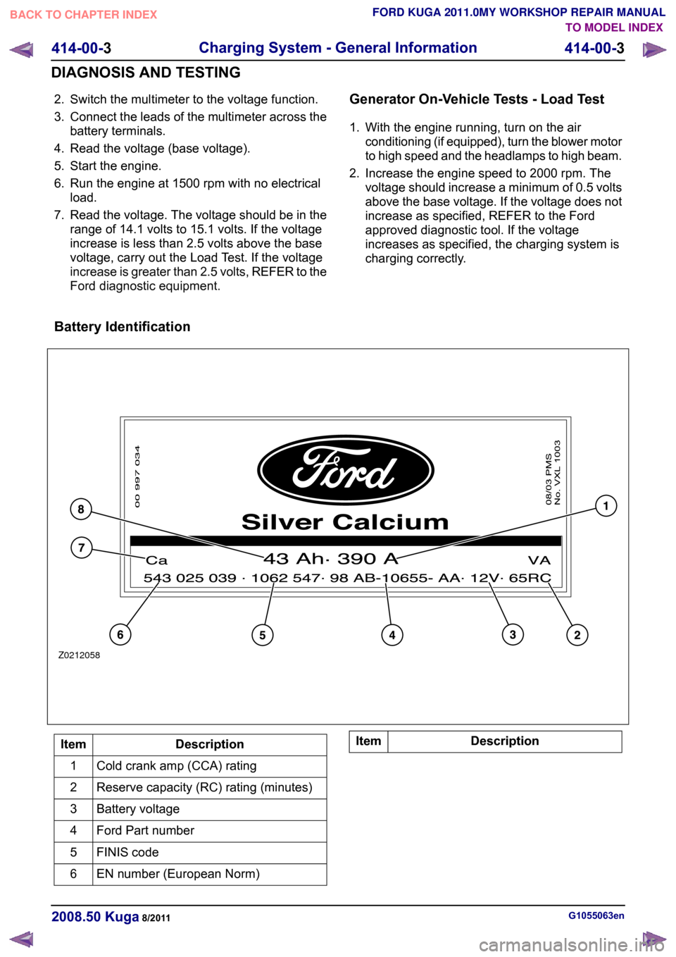
Battery Identification Description
Item
Cold crank amp (CCA) rating
1
Reserve capacity (RC) rating (minutes)
2
Battery voltage
3
Ford Part number
4
FINIS code
5
EN number (European Norm)
6 Description
Item G1055063en
2008.50 Kuga 8/2011 414-00-3
Charging System - General Information
414-00-3
DIAGNOSIS AND TESTINGTO MODEL INDEX
BACK TO CHAPTER INDEX
FORD KUGA 2011.0MY WORKSHOP REPAIR MANUALZ0212058
Page 338 of 2057

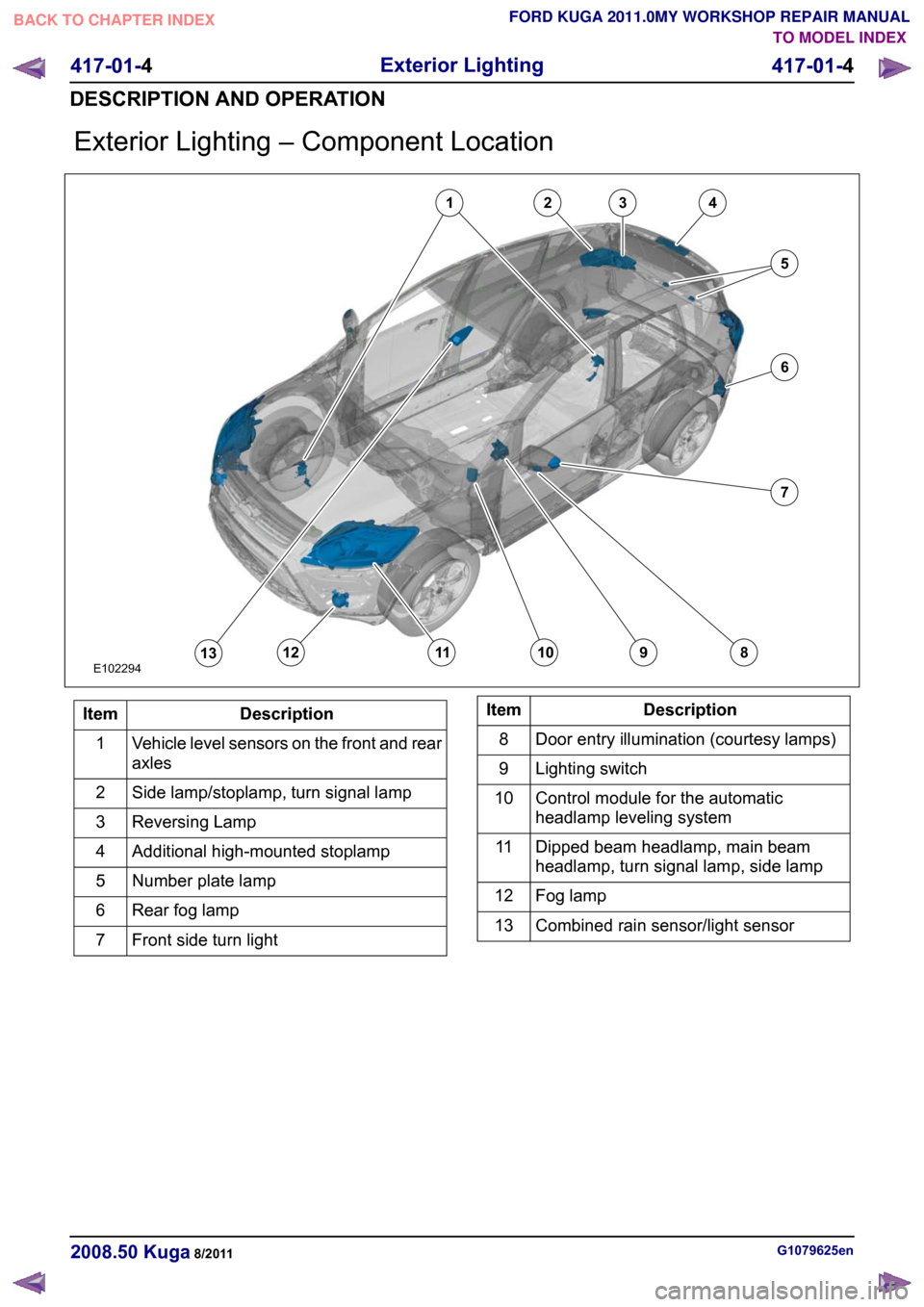
Exterior Lighting – Component Location
Description
Item
Vehicle level sensors on the front and rear
axles
1
Side lamp/stoplamp, turn signal lamp
2
Reversing Lamp
3
Additional high-mounted stoplamp
4
Number plate lamp
5
Rear fog lamp
6
Front side turn light
7 Description
Item
Door entry illumination (courtesy lamps)
8
Lighting switch
9
Control module for the automatic
headlamp leveling system
10
Dipped beam headlamp, main beam
headlamp, turn signal lamp, side lamp
11
Fog lamp
12
Combined rain sensor/light sensor
13 G1079625en
2008.50 Kuga 8/2011 417-01-4
Exterior Lighting
417-01-4
DESCRIPTION AND OPERATIONTO MODEL INDEX
BACK TO CHAPTER INDEX
FORD KUGA 2011.0MY WORKSHOP REPAIR MANUALE10229412345678910111213
Page 340 of 2057

The turn signal lamps and side lights are the same as in conventional headlamps.
Bulb color
Current draw
Bulb
Lamp
Clear
35W
D1S
Low-beams
Clear
55W
H1
High beam headlamp
Clear
21W
H21W
Turn signal indicator
Clear
5W
W5W
Side lamp
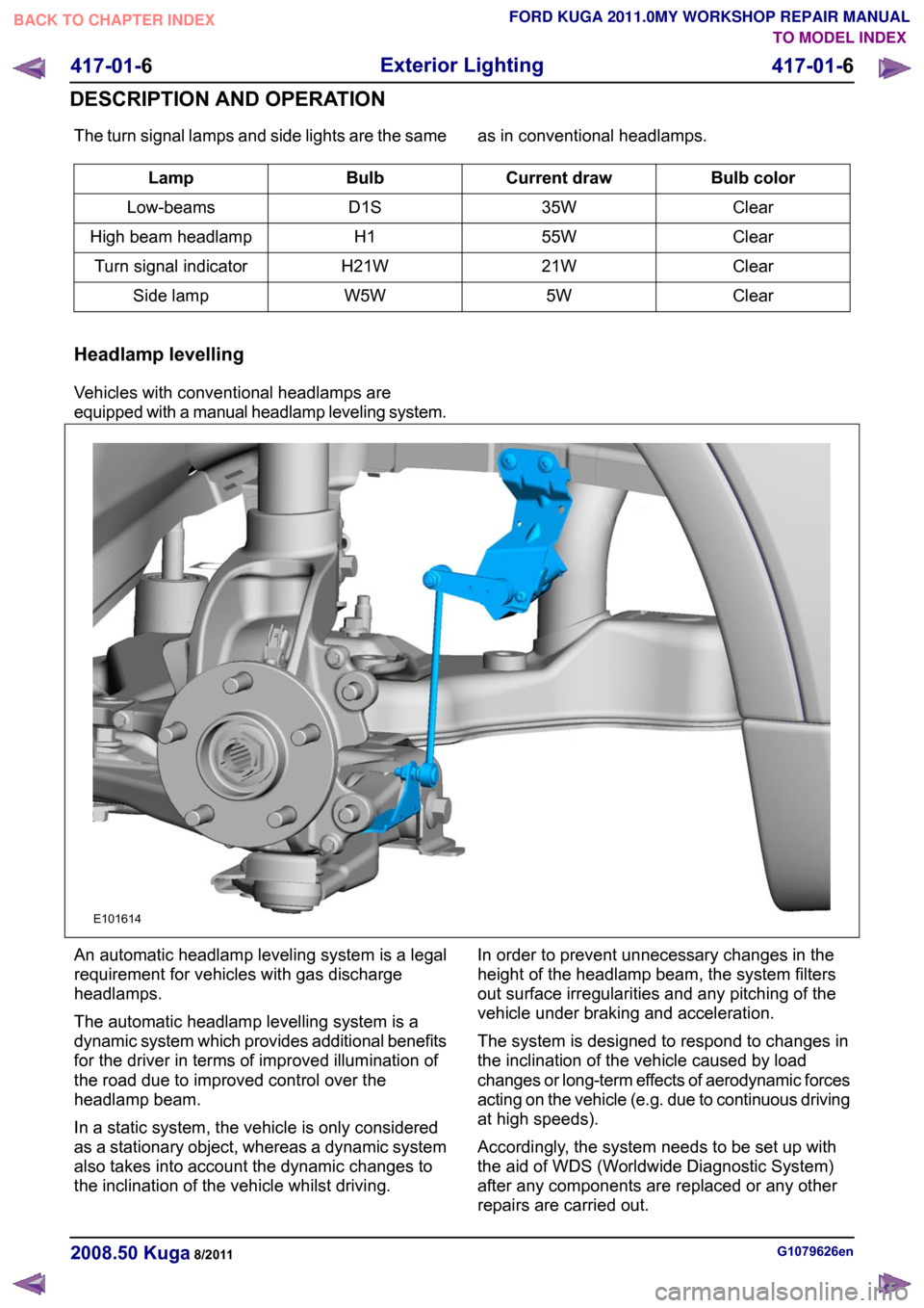
Headlamp levelling
Vehicles with conventional headlamps are
equipped with a manual headlamp leveling system. An automatic headlamp leveling system is a legal
requirement for vehicles with gas discharge
headlamps.
The automatic headlamp levelling system is a
dynamic system which provides additional benefits
for the driver in terms of improved illumination of
the road due to improved control over the
headlamp beam.
In a static system, the vehicle is only considered
as a stationary object, whereas a dynamic system
also takes into account the dynamic changes to
the inclination of the vehicle whilst driving.
In order to prevent unnecessary changes in the
height of the headlamp beam, the system filters
out surface irregularities and any pitching of the
vehicle under braking and acceleration.
The system is designed to respond to changes in
the inclination of the vehicle caused by load
changes or long-term effects of aerodynamic forces
acting on the vehicle (e.g. due to continuous driving
at high speeds).
Accordingly, the system needs to be set up with
the aid of WDS (Worldwide Diagnostic System)
after any components are replaced or any other
repairs are carried out.
G1079626en
2008.50 Kuga 8/2011 417-01-6
Exterior Lighting
417-01-6
DESCRIPTION AND OPERATIONTO MODEL INDEX
BACK TO CHAPTER INDEX
FORD KUGA 2011.0MY WORKSHOP REPAIR MANUALE101614
Page 341 of 2057

Combined rain sensor/light sensor
CAUTIONS:
On vehicles with autolamps, retrofitting
with daytime running lamps is not
permissible, as otherwise, the engine
cannot be stopped when the lighting is
switched on.
On vehicles with autolamps, the daytime
running lamp fuse must not be fitted, as
otherwise, the engine cannot be stopped
when the lighting is switched on.
The combined rain sensor/light sensor is located
behind the interior rear view mirror.
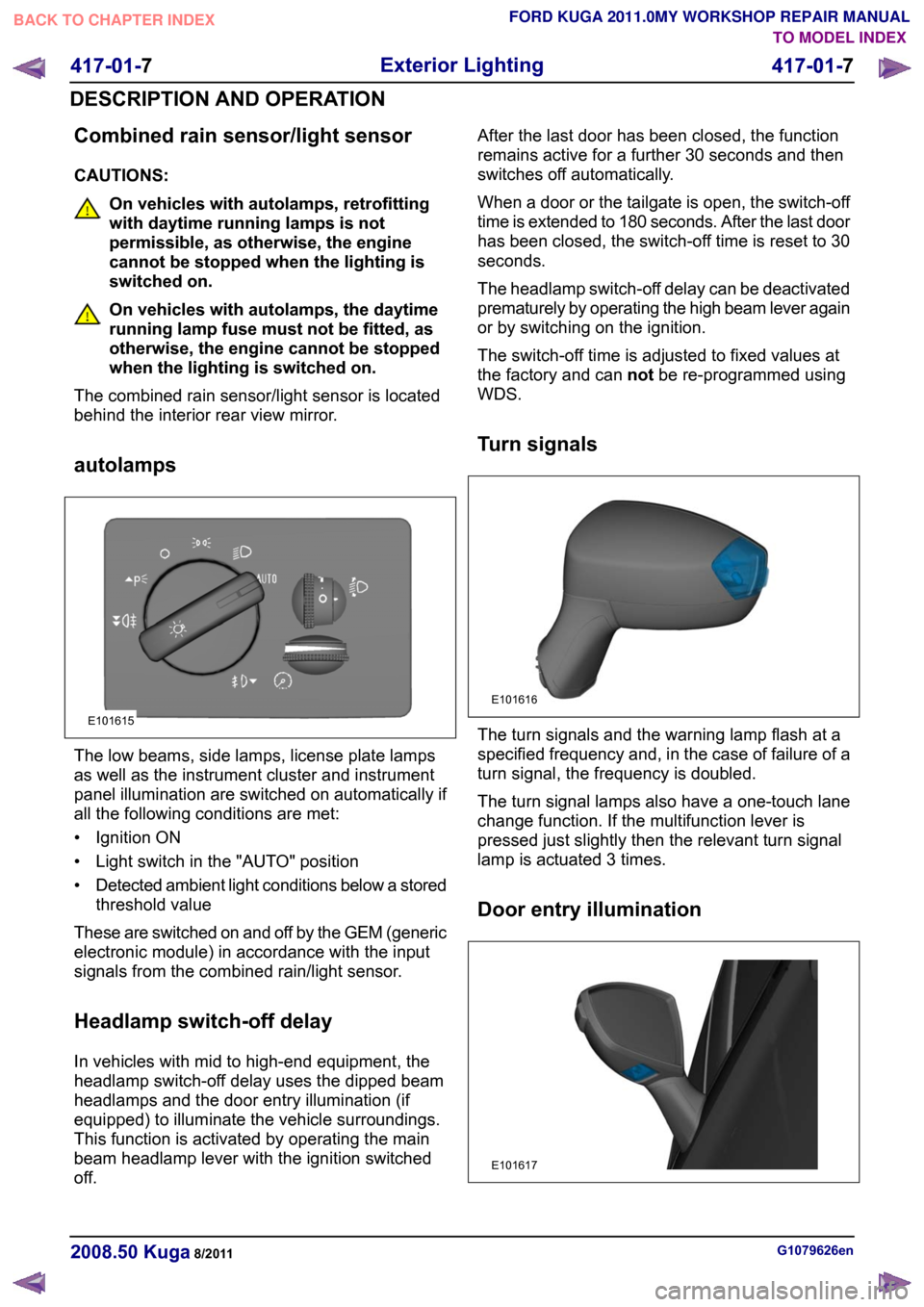
autolamps The low beams, side lamps, license plate lamps
as well as the instrument cluster and instrument
panel illumination are switched on automatically if
all the following conditions are met:
• Ignition ON
• Light switch in the "AUTO" position
•
Detected ambient light conditions below a stored
threshold value
These are switched on and off by the GEM (generic
electronic module) in accordance with the input
signals from the combined rain/light sensor.
Headlamp switch-off delay
In vehicles with mid to high-end equipment, the
headlamp switch-off delay uses the dipped beam
headlamps and the door entry illumination (if
equipped) to illuminate the vehicle surroundings.
This function is activated by operating the main
beam headlamp lever with the ignition switched
off. After the last door has been closed, the function
remains active for a further 30 seconds and then
switches off automatically.
When a door or the tailgate is open, the switch-off
time is extended to 180 seconds. After the last door
has been closed, the switch-off time is reset to 30
seconds.
The headlamp switch-off delay can be deactivated
prematurely by operating the high beam lever again
or by switching on the ignition.
The switch-off time is adjusted to fixed values at
the factory and can
notbe re-programmed using
WDS.
Turn signals The turn signals and the warning lamp flash at a
specified frequency and, in the case of failure of a
turn signal, the frequency is doubled.
The turn signal lamps also have a one-touch lane
change function. If the multifunction lever is
pressed just slightly then the relevant turn signal
lamp is actuated 3 times.
Door entry illumination
G1079626en
2008.50 Kuga 8/2011 417-01-7
Exterior Lighting
417-01-7
DESCRIPTION AND OPERATIONTO MODEL INDEX
BACK TO CHAPTER INDEX
FORD KUGA 2011.0MY WORKSHOP REPAIR MANUALE101615 E101616 E101617
Page 360 of 2057

Turn Signal and Hazard Lamps
Refer to Wiring Diagrams Section 417-01, for
schematic and connector information.
Special Tool(s) / General Equipment
Terminal Probe Kit
29-011AThe Ford approved diagnostic tool
Description of operation
A diagnosis of the generic electronic module (GEM)
can be performed with the Ford approved
diagnostic tool. Furthermore, an integrated service
mode enables testing of the input and output
signals without the need for further tools. To enable
activation of service mode:
• switch off the ignition,
• switch off all other electrical consumers,
• apply the handbrake,
• shift to neutral
• and close the doors.
Activating the service mode
Proceed as follows to activate the service mode:
• OPERATE the switch of the heated rear window
and HOLD IT THERE
• Turn on the ignition.
• RELEASE the switch of the heated rear window
A signal sounds and the turn signal lamps come
on to indicate that service mode has been
successfully activated.
NOTE: If the alarm is activated (in vehicles fitted
with an anti-theft alarm system), service mode
cannot be activated.
Inputs
SWITCH the windshield wiper switch to the "OFF"
position to test the input signals. The following is
a list of the switch signals to be tested, in no
particular order:
• Turn signals (right, left, hazard warning lights)
• Windshield wiper stage I • Windshield wiper stage II
• Windshield washer system
• Rear window wiper
• Rear window washer system
• Doors open/closed
• Remote control for central locking with double
locking
• Hood open/closed (in vehicles equipped with an anti-theft alarm system)
• Tailgate open/closed
• A/C request signal
• Heated windscreen (if fitted)
• Parking Brake
• Brake reservoir fluid level
• Speed control system
• Autolamps
• Low beam
• High beam
• Headlamp flasher
• Marker Lamps
• Reversing lamp
• Liftgate release
• Ignition switch, terminal 15 (turn key to 0 position, then turn key to II position.)
An acoustic signal sounds and the turn signal
lamps flash to indicate receipt of each input signal
by the generic electronic module.
Test the windshield wiper "intermittent mode" stage
input signal (only vehicles with adjustable
intermittent mode)
The windshield wiper switch must be switched to
"intermittent mode" in order to test the input signal.
The delay times of the input signals can then be
tested by operating the rotary switch. Each change
of the rotary switch position is indicated by an
acoustic signal and illumination of the turn signals.
Output signals
SWITCH the wiper switch to the "intermittent""
position to test the output signals. PRESSING the
heated rear window switch activates the output
signals in the following order:
a. Turn Indicator Left Hand
b. Turn Indicator Right Hand
c. High beam
d. Low beam G1055002en
2008.50 Kuga 8/2011 417-01-26
Exterior Lighting
417-01-26
DIAGNOSIS AND TESTINGTO MODEL INDEX
BACK TO CHAPTER INDEX
FORD KUGA 2011.0MY WORKSHOP REPAIR MANUAL29011A
Page 452 of 2057

Module Controlled Functions – Overview
Generic electronics module (GEM)
CAUTIONS:
Never swap the GEM (generic electronic
module) between two vehicles.
Compare the number of relays and fuses
in the defective GEM and the new GEM.
Transfer from the defective GEM any relays
and fuses which are not in the new GEM.
In doing so, pay attention that fuses with
the correct Ampere rating are used, by
referring to the wiring diagrams.
NOTE: The GEM is integrated in the CJB (central
junction box) and cannot be replaced as a separate
unit.
For repair work during a service, vehicle-specific
configuration is necessary if a new GEM is
installed.
Emergency function
The GEM is equipped with restricted emergency
running functions on vehicles with mid or high-end
equipment levels.
The microcontroller sends a control signal to a
monitoring function within the GEM at regular
intervals. If the battery voltage falls below a value
of approx. 7.5 volts, this check signal is not present
and the GEM switches to emergency function after
a predetermined time.
In this case, the low beam is permanently switched
on, regardless of the light switch position. The
windshield wiper can only be operated in stage 1;
the wiper switch must however be in the stage I or
II position. The wiper park position is not
recognized. Intermittent wiping is not available.
When the control signal recurs, the GEM switches
back to normal operation.
Service mode
Description of operation
Diagnosis of the GEM can be carried out using the
Ford diagnostic unit. Furthermore, an integrated
service mode enables testing of the input and
output signals without the need for further tools.
To enable activation of service mode: • switch off the ignition,
• switch off all other electrical consumers,
• apply the handbrake,
• Shift to neutral
• and close the doors.
Activating the service mode
NOTE:
If the alarm is activated (in vehicles fitted
with an anti-theft alarm system), service mode
cannot be activated.
Proceed as follows to activate the service mode:
• OPERATE the switch of the heated rear window
and HOLD IT THERE
• SWITCH ON the ignition.
• RELEASE the switch of the heated rear window
A signal sounds and the turn signal lamps come
on to indicate that service mode has been
successfully activated.
Inputs
SWITCH the windshield wiper switch to the "OFF"
position to test the input signals. The following is
a list of the switch signals to be tested, in no
particular order:
• Windshield wiper stage I
• Windshield wiper stage II
• Windshield washer system
• Rear window wiper
• Rear window washer system
• Doors open/closed
• Remote control for central locking with double locking
• Hood open/closed (in vehicles equipped with an anti-theft alarm system)
• Tailgate open/closed
• A/C request signal
• Heated windscreen (if fitted)
• Parking brake
• Brake fluid level
• Cruise control system
• Autolamps
• Dipped beam
• Main beam
• Headlamp flasher
• Side lights
• Turn signals (right, left, hazard warning lights) G1030787en
2008.50 Kuga 8/2011 419-10-2
Multifunction Electronic Modules
419-10-2
DESCRIPTION AND OPERATIONTO MODEL INDEX
BACK TO CHAPTER INDEX
FORD KUGA 2011.0MY WORKSHOP REPAIR MANUAL
Page 457 of 2057

Electrical consumers are switched off when the
battery voltage is low if the GEM determines (as a
result of the message received from the PCM on
the CAN bus via the instrument cluster) that the
battery voltage has dropped below the threshold
value.
When the threshold for low battery voltage is
reached the GEM switches off the following
consumers in this order at intervals of 5 seconds:
• Heated windscreen
• Heated rear window
• Electric booster Heater
• A/C system
If the battery voltage increases back above the
lower threshold then all of the consumers which
were previously switched off are reactivated by the
GEM.
Once the electric consumers have been reactivated
their status is "switched off", i.e. the consumers
are switched off and await an input signal provided
from the relevant switch via the GEM; this means
that the driver needs to switch these components
back on again.
Electrical consumers are switched on when the
battery voltage is excessively high if the GEM
determines that the battery voltage has increased
above the threshold for overvoltage and the
charging system warning indicator has come on.
When the threshold is reached the GEM switches
on the following consumers in this order at intervals
of 5 seconds:
• Heated windscreen
• Heated rear window
When these components are deactivated again
their status is "switched off". This means that the
consumers are waiting for an input signal provided
from the relevant switch via the GEM.
Ignition overload protection
The ignition overload protection intermittently
disconnects certain circuits in order to restrict the
current being drawn from the battery while the
starter motor is operating.
The position of the ignition switch is broadcast by
the instrument cluster on the medium speed CAN
bus.
The ignition overload protection relay which is
integrated in the battery junction box is activated
by the GEM if the message "ignition switch in
position III" is received from the instrument cluster.
All of the electric consumers controlled by the
ignition overload protection relay are then switched
off.
The following consumers (among others) are
controlled by the ignition overload protection relay:
• Fog lamps
• Windscreen/rear window wash/wipe systems
• Backup lamps
• Heated washer nozzles
• Heating blower motor
• Seat heating
Headlamp switch-off delay
The headlamp switch-off delay utilizes the low
beam together with the peripheral lights (if
equipped) to illuminate the area surrounding the
vehicle. The function is activated by operating the
high beam lever when the ignition switch is in the
"0" position.
After the last door has been closed, the function
remains active for a further 30 seconds and then
switches off automatically.
When a door or the tailgate is open, the switch-off
time is extended to 180 seconds. After the last door
has been closed, the switch-off time is reset to 30
seconds.
The headlamp switch-off delay can be deactivated
prematurely by operating the high beam lever again
or by switching on the ignition.
The switch-off time is adjusted to set values at the
factory and cannot be re-programmed using the
Ford diagnostic unit.
G1030788en
2008.50 Kuga 8/2011 419-10-7
Multifunction Electronic Modules
419-10-7
DESCRIPTION AND OPERATIONTO MODEL INDEX
BACK TO CHAPTER INDEX
FORD KUGA 2011.0MY WORKSHOP REPAIR MANUAL