ECO mode FORD MONDEO 1993 Service User Guide
[x] Cancel search | Manufacturer: FORD, Model Year: 1993, Model line: MONDEO, Model: FORD MONDEO 1993Pages: 279, PDF Size: 12.71 MB
Page 99 of 279
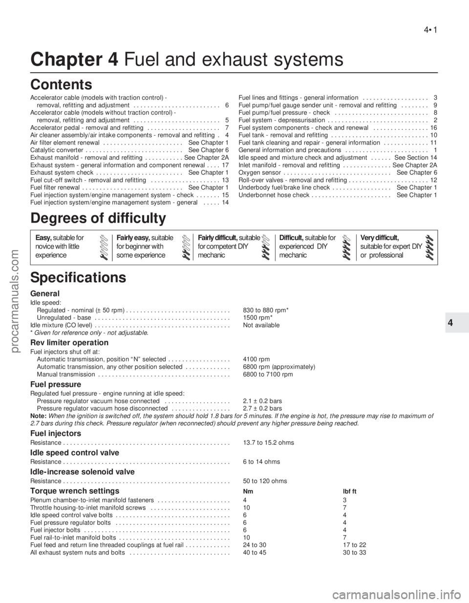
Chapter 4 Fuel and exhaust systems
Accelerator cable (models with traction control) -
removal, refitting and adjustment . . . . . . . . . . . . . . . . . . . . . . . . . 6
Accelerator cable (models without traction control) -
removal, refitting and adjustment . . . . . . . . . . . . . . . . . . . . . . . . . 5
Accelerator pedal - removal and refitting . . . . . . . . . . . . . . . . . . . . . 7
Air cleaner assembly/air intake components - removal and refitting . 4
Air filter element renewal . . . . . . . . . . . . . . . . . . . . . . . See Chapter 1
Catalytic converter . . . . . . . . . . . . . . . . . . . . . . . . . . . . See Chapter 6
Exhaust manifold - removal and refitting . . . . . . . . . . . See Chapter 2A
Exhaust system - general information and component renewal . . . . 17
Exhaust system check . . . . . . . . . . . . . . . . . . . . . . . . . See Chapter 1
Fuel cut-off switch - removal and refitting . . . . . . . . . . . . . . . . . . . . 13
Fuel filter renewal . . . . . . . . . . . . . . . . . . . . . . . . . . . . . See Chapter 1
Fuel injection system/engine management system - check . . . . . . . 15
Fuel injection system/engine management system - general . . . . . 14Fuel lines and fittings - general information . . . . . . . . . . . . . . . . . . . 3
Fuel pump/fuel gauge sender unit - removal and refitting . . . . . . . . 9
Fuel pump/fuel pressure - check . . . . . . . . . . . . . . . . . . . . . . . . . . . 8
Fuel system - depressurisation . . . . . . . . . . . . . . . . . . . . . . . . . . . . . 2
Fuel system components - check and renewal . . . . . . . . . . . . . . . . 16
Fuel tank - removal and refitting . . . . . . . . . . . . . . . . . . . . . . . . . . . . 10
Fuel tank cleaning and repair - general information . . . . . . . . . . . . . 11
General information and precautions . . . . . . . . . . . . . . . . . . . . . . . . 1
Idle speed and mixture check and adjustment . . . . . . See Section 14
Inlet manifold - removal and refitting . . . . . . . . . . . . . . See Chapter 2A
Oxygen sensor . . . . . . . . . . . . . . . . . . . . . . . . . . . . . . . See Chapter 6
Roll-over valves - removal and refitting . . . . . . . . . . . . . . . . . . . . . . . 12
Underbody fuel/brake line check . . . . . . . . . . . . . . . . . See Chapter 1
Underbonnet hose check . . . . . . . . . . . . . . . . . . . . . . . See Chapter 1
General
Idle speed:
Regulated - nominal (± 50 rpm) . . . . . . . . . . . . . . . . . . . . . . . . . . . . . . 830 to 880 rpm*
Unregulated - base . . . . . . . . . . . . . . . . . . . . . . . . . . . . . . . . . . . . . . . 1500 rpm*
Idle mixture (CO level) . . . . . . . . . . . . . . . . . . . . . . . . . . . . . . . . . . . . . . . Not available
* Given for reference only - not adjustable.
Rev limiter operation
Fuel injectors shut off at:
Automatic transmission, position “N” selected . . . . . . . . . . . . . . . . . . 4100 rpm
Automatic transmission, any other position selected . . . . . . . . . . . . . 6800 rpm (approximately)
Manual transmission . . . . . . . . . . . . . . . . . . . . . . . . . . . . . . . . . . . . . . 6800 to 7100 rpm
Fuel pressure
Regulated fuel pressure - engine running at idle speed:
Pressure regulator vacuum hose connected . . . . . . . . . . . . . . . . . . . 2.1 ± 0.2 bars
Pressure regulator vacuum hose disconnected . . . . . . . . . . . . . . . . . 2.7 ± 0.2 bars
Note:When the ignition is switched off, the system should hold 1.8 bars for 5 minutes. If the engine is hot, the pressure may rise to maximum of
2.7 bars during this check. Pressure regulator (when reconnected) should prevent any higher pressure being reached.
Fuel injectors
Resistance . . . . . . . . . . . . . . . . . . . . . . . . . . . . . . . . . . . . . . . . . . . . . . . . 13.7 to 15.2 ohms
Idle speed control valve
Resistance . . . . . . . . . . . . . . . . . . . . . . . . . . . . . . . . . . . . . . . . . . . . . . . . 6 to 14 ohms
Idle-increase solenoid valve
Resistance . . . . . . . . . . . . . . . . . . . . . . . . . . . . . . . . . . . . . . . . . . . . . . . . 50 to 120 ohms
Torque wrench settingsNm lbf ft
Plenum chamber-to-inlet manifold fasteners . . . . . . . . . . . . . . . . . . . . . 4 3
Throttle housing-to-inlet manifold screws . . . . . . . . . . . . . . . . . . . . . . . 10 7
Idle speed control valve bolts . . . . . . . . . . . . . . . . . . . . . . . . . . . . . . . . . 6 4
Fuel pressure regulator bolts . . . . . . . . . . . . . . . . . . . . . . . . . . . . . . . . . 6 4
Fuel injector bolts . . . . . . . . . . . . . . . . . . . . . . . . . . . . . . . . . . . . . . . . . . 6 4
Fuel rail-to-inlet manifold bolts . . . . . . . . . . . . . . . . . . . . . . . . . . . . . . . . 10 7
Fuel feed and return line threaded couplings at fuel rail . . . . . . . . . . . . . 24 to 30 17 to 22
All exhaust system nuts and bolts . . . . . . . . . . . . . . . . . . . . . . . . . . . . . 40 to 45 30 to 33
4•1
Easy,suitable for
novice with little
experienceFairly easy,suitable
for beginner with
some experienceFairly difficult,suitable
for competent DIY
mechanicDifficult,suitable for
experienced DIY
mechanicVery difficult,
suitable for expert DIY
or professional
Degrees of difficulty
Specifications Contents
4
procarmanuals.com
Page 103 of 279
which pulley, disconnect the first cable end
nipple from the throttle actuator’s upper
pulley, then slide the cable outer upwards out
of the actuator housing. Disconnect the
second cable in the same way from the
actuator’s lower pulley.
6Working in the passenger compartment,
reach up to the top of the accelerator pedal.
Pull the end fitting and collar out of the pedal,
then release the cable inner wire through the
slot in the pedal. Tie a length of string to the
end of the cable.
7Returning to the engine compartment, pull
the cable through the bulkhead until the string
can be untied and the pedal-to-actuator cable
removed.
Refitting
8Refitting is the reverse of the removal
procedure. Use the string to draw the pedal-
to-actuator cable through the bulkhead.
Ensure that each cable end is connected to
the correct actuator pulley.
9Adjust both cables as described below.
Adjustment
Note:Both sections of the cable must be
adjusted together, even if only one has been
disturbed.
10Remove the plenum chamber (see
Section 4).
11Remove the metal clip from the adjuster
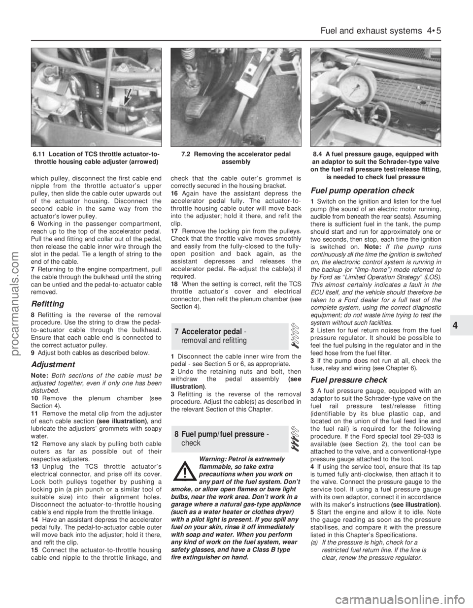
of each cable section (see illustration), and
lubricate the adjusters’ grommets with soapy
water.
12Remove any slack by pulling both cable
outers as far as possible out of their
respective adjusters.
13Unplug the TCS throttle actuator’s
electrical connector, and prise off its cover.
Lock both pulleys together by pushing a
locking pin (a pin punch or a similar tool of
suitable size) into their alignment holes.
Disconnect the actuator-to-throttle housing
cable’s end nipple from the throttle linkage.
14Have an assistant depress the accelerator
pedal fully. The pedal-to-actuator cable outer
will move back into the adjuster; hold it there,
and refit the clip.
15Connect the actuator-to-throttle housing
cable end nipple to the throttle linkage, andcheck that the cable outer’s grommet is
correctly secured in the housing bracket.
16Again have the assistant depress the
accelerator pedal fully. The actuator-to-
throttle housing cable outer will move back
into the adjuster; hold it there, and refit the
clip.
17Remove the locking pin from the pulleys.
Check that the throttle valve moves smoothly
and easily from the fully-closed to the fully-
open position and back again, as the
assistant depresses and releases the
accelerator pedal. Re-adjust the cable(s) if
required.
18When the setting is correct, refit the TCS
throttle actuator’s cover and electrical
connector, then refit the plenum chamber (see
Section 4).
1Disconnect the cable inner wire from the
pedal - see Section 5 or 6, as appropriate.
2Undo the retaining nuts and bolt, then
withdraw the pedal assembly (see
illustration).
3Refitting is the reverse of the removal
procedure. Adjust the cable(s) as described in
the relevant Section of this Chapter.
Warning: Petrol is extremely
flammable, so take extra
precautions when you work on
any part of the fuel system. Don’t
smoke, or allow open flames or bare light
bulbs, near the work area. Don’t work in a
garage where a natural gas-type appliance
(such as a water heater or clothes dryer)
with a pilot light is present. If you spill any
fuel on your skin, rinse it off immediately
with soap and water. When you perform
any kind of work on the fuel system, wear
safety glasses, and have a Class B type
fire extinguisher on hand.
Fuel pump operation check
1Switch on the ignition and listen for the fuel
pump (the sound of an electric motor running,
audible from beneath the rear seats). Assuming
there is sufficient fuel in the tank, the pump
should start and run for approximately one or
two seconds, then stop, each time the ignition
is switched on. Note:If the pump runs
continuously all the time the ignition is switched
on, the electronic control system is running in
the backup (or “limp-home”) mode referred to
by Ford as “Limited Operation Strategy” (LOS).
This almost certainly indicates a fault in the
ECU itself, and the vehicle should therefore be
taken to a Ford dealer for a full test of the
complete system, using the correct diagnostic
equipment; do not waste time trying to test the
system without such facilities.
2Listen for fuel return noises from the fuel
pressure regulator. It should be possible to
feel the fuel pulsing in the regulator and in the
feed hose from the fuel filter.
3If the pump does not run at all, check the
fuse, relay and wiring (see Chapter 6).
Fuel pressure check
3A fuel pressure gauge, equipped with an
adaptor to suit the Schrader-type valve on the
fuel rail pressure test/release fitting
(identifiable by its blue plastic cap, and
located on the union of the fuel feed line and
the fuel rail) is required for the following
procedure. If the Ford special tool 29-033 is
available (see Section 2), the tool can be
attached to the valve, and a conventional-type
pressure gauge attached to the tool.
4If using the service tool, ensure that its tap
is turned fully anti-clockwise, then attach it to
the valve. Connect the pressure gauge to the
service tool. If using a fuel pressure gauge
with its own adaptor, connect it in accordance
with its maker’s instructions (see illustration).
5Start the engine and allow it to idle. Note
the gauge reading as soon as the pressure
stabilises, and compare it with the pressure
listed in this Chapter’s Specifications.
(a) If the pressure is high, check for a
restricted fuel return line. If the line is
clear, renew the pressure regulator.
8 Fuel pump/fuel pressure -
check
7 Accelerator pedal -
removal and refitting
Fuel and exhaust systems 4•5
4
6.11 Location of TCS throttle actuator-to-
throttle housing cable adjuster (arrowed)7.2 Removing the accelerator pedal
assembly8.4 A fuel pressure gauge, equipped with
an adaptor to suit the Schrader-type valve
on the fuel rail pressure test/release fitting,
is needed to check fuel pressure
procarmanuals.com
Page 105 of 279
the ring square to the tank and turning it at the
same time.
10Maintain the pressure while an assistant
refits and engages the retaining ring. When
the ring is engaged in the tank lugs, turn it
clockwise to tighten it until it is secured.
11The remainder of the refitting procedure is
the reverse of removal. Observe the colour-
coding to ensure that the fuel pipes are
reconnected to the correct unions.
Warning: The fuel system pressure
must be released before any part
of the system is disturbed - see
Section 2. Petrol is extremely
flammable, so take extra precautions when
you work on any part of the fuel system.
Don’t smoke, or allow open flames or bare
light bulbs, near the work area. Don’t work
in a garage where a natural gas-type
appliance (such as a water heater or clothes
dryer) with a pilot light is present. If you spill
any fuel on your skin, rinse it off
immediately with soap and water. When you
perform any kind of work on the fuel
system, wear safety glasses, and have a
Class B type fire extinguisher on hand.
1A fuel tank drain plug is not provided; it is
therefore preferable to carry out the removal
operation when the tank is nearly empty.
Before proceeding, disconnect the battery
negative (earth) lead, and syphon or hand-
pump the remaining fuel from the tank.
Alternatively, disconnect the feed pipe from
the fuel filter (see Chapter 1), and connect a
spare length of hose to this so that when the
ignition is switched on, the fuel pump will
empty the tank into a clean container. If this
approach is adopted, ensure that the
container is large enough to take all the fuel in
the tank, and be careful to take all suitable
precautions to prevent the risk of fire. Note:
Before disconnecting or opening any part of
the fuel system, relieve the residual pressure
(see Section 2), and equalise tank pressure by
removing the fuel filler cap. Also disconnect
the battery negative (earth) lead - see Chap-
ter 5, Section 1.2Unbolt or fold forwards (as appropriate) the
rear seat base cushion (see Chapter 11).
Withdraw from the vehicle’s floor the grommet
covering the fuel pump/sender unit. Unplug
the fuel pump/sender unit’s electrical
connector, and disconnect the fuel return pipe
(coded red) from the unit (see Section 9).
3Raise the rear of the vehicle, and support it
securely on axle stands. Get underneath and
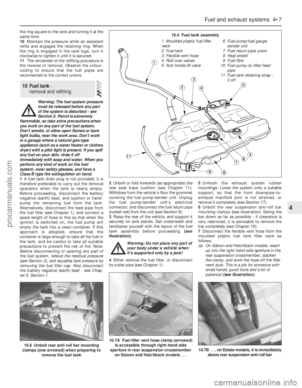
familiarise yourself with the layout of the fuel
tank assembly before proceeding (see
illustration).
Warning: Do not place any part of
your body under a vehicle when
it’s supported only by a jack!
4Either remove the fuel filter, or disconnect
its outlet pipe (see Chapter 1).5Unhook the exhaust system rubber
mountings. Lower the system onto a suitable
support, so that the front downpipe-to-
exhaust manifold joint is not strained, or
remove it completely (see Section 17).
6Unbolt the rear suspension anti-roll bar
mounting clamps (see illustration). Swing the
bar down as far as possible - if clearance is
very restricted, it is advisable to remove the
bar completely (see Chapter 10).
7Disconnect the flexible vent hose from the
moulded plastic fuel tank filler neck as
follows:
(a) On Saloon and Hatchback models, reach
up into the right-hand side aperture in the
rear suspension crossmember, slacken
the clamp, and work the hose off the filler
neck stub. This is a job for someone with
small hands, good tools and a lot of
patience! (see illustration).
10 Fuel tank -
removal and refitting
Fuel and exhaust systems 4•7
4
10.6 Unbolt rear anti-roll bar mounting
clamps (one arrowed) when preparing to
remove the fuel tank10.7A Fuel filler vent hose clamp (arrowed)
is accessible through right-hand side
aperture in rear suspension crossmember
on Saloon and Hatchback models . . .
10.7B . . . on Estate models, it is immediately
above rear suspension anti-roll bar
10.4 Fuel tank assembly
1 Moulded plastic fuel filler
neck
2 Fuel tank
3 Flexible vent hose
4 Roll-over valves
5 Anti-trickle fill valve6 Fuel pump/fuel gauge
sender unit
7 Fuel return pipe union
8 Heat shield
9 Fuel filter
10 Fuel pump-to-filter feed
pipe
11 Fuel tank retaining strap -
2 off
procarmanuals.com
Page 107 of 279
into the inlet ports, just above the inlet valves,
by four fuel injectors. The system also
includes features such as the flushing of fresh
(ie, cold) fuel around each injector on start-up,
thus improving hot starts.
The amount of fuel supplied by the injectors
is precisely controlled by an Electronic
Control Unit (ECU). The ECU uses the signals
derived from the engine speed/crankshaft
position sensor and the camshaft position
sensor, to trigger each injector separately in
cylinder firing order (sequential injection), with
benefits in terms of better fuel economy and
lower exhaust emissions.
Air induction system
The air system consists of an air filter
housing, an air mass meter, an intake
resonator and plenum chamber, and a throttle
housing. The air mass meter is an information-
gathering device for the ECU; it uses a “hot-
wire” system to send the ECU a constantly-
varying (analogue) voltage signal
corresponding to the volume of air passing
into the engine. Another sensor in the air mass
meter measures intake air temperature. The
ECU uses these signals to calculate the mass
of air entering the engine.
The throttle valve inside the throttle housing
is controlled by the driver, through the
accelerator pedal. As the valve opens, the
amount of air that can pass through the
system increases. The throttle potentiometer
opens further, the air mass meter’s signal
alters, and the ECU opens each injector for a
longer duration, to increase the amount of fuel
delivered to the inlet ports.
Electronic control system
The ECU controls the fuel injection system,
as well as the other sub-systems which make
up the entire engine management system. It
receives signals from a number of information
sensors, which monitor such variables as
intake air mass and temperature, coolant
temperature, engine speed and position,
acceleration/deceleration, and exhaust gas
oxygen content. These signals help the ECU
determine the injection duration necessary for
the optimum air/fuel ratio. These sensors and
associated ECU-controlled relays are located
throughout the engine compartment. For
further information regarding the ECU and its
control of the engine management system,
see Chapter 6.
Idle speed and mixture
adjustment - general
Both the idle speed and mixture are under
the control of the ECU, and cannot be
adjusted. Not only can they not be adjusted,
they cannot even be checked, except with the
use of special diagnostic equipment (see
Chapter 6) - this makes it a task for a Ford
dealer service department. Do notattempt to
“adjust” these settings in any way without
such equipment.
If the idle speed and mixture are thought tobe incorrect, take the vehicle to a Ford dealer
for the complete system to be tested.
On models equipped with a heated
windscreen, an idle-increase solenoid valve is
fitted, which raises the idle speed to
compensate for the increased load on the
engine when the heated windscreen is
switched on. When the valve is open, air from
the plenum chamber bypasses the throttle
housing and idle speed control valve, passing
directly into the inlet manifold through the
union on its left-hand end. The system is
active only for the four minutes that the
heated windscreen circuit is live, and is
supplementary to the main (ECU-controlled)
idle speed regulation.
Warning: Petrol is extremely
flammable, so extra precautions
must be taken when working on
any part of the fuel system. Do
not smoke, or allow open flames or bare
light bulbs, near the work area. Don’t work
in a garage if a natural gas-type appliance
with a pilot light is present. While
performing any work on the fuel system,
wear safety glasses, and have a dry
chemical (Class B) fire extinguisher on
hand. If you spill any fuel on your skin,
rinse it off immediately with soap and
water.
Note: This is an initial check of the fuel delivery
and air induction sub-systems of the engine
management system, to be carried out in
conjunction with the operational check of the
fuel pump (see Section 8), and as part of the
preliminary checks of the complete engine
management system (see Section 3 of
Chapter 6).
1Check the earth wire connections for
tightness. Check all wiring and electrical
connectors that are related to the system.
Loose electrical connectors and poor earths
can cause many problems that resemble
more serious malfunctions.
2Check to see that the battery is fully-
charged. The ECU and sensors depend on an
accurate supply voltage to properly meter the
fuel.
3Check the air filter element - a dirty or
partially-blocked filter will severely impede
performance and economy (see Chapter 1).
4If a blown fuse is found, renew it and see if
it blows again. If it does, search for a short-
circuited wire in the harness related to the
system (see Chapter 6).
5Check the air intake duct from the intake to
the inlet manifold for leaks, which will result in
an excessively-lean mixture. Also check the
condition of the vacuum hoses connected to
the inlet manifold.
6Remove the plenum chamber from the
throttle housing. Check the throttle valve for
dirt, carbon or other residue build-up. If it’sdirty, seek the advice of a Ford dealer - since
the electronic control system is designed to
compensate for factors such as the build-up
of dirt in the throttle housing, it may well be
best to leave it dirty, unless the deposits are
extensive. Note: A warning label on the
housing states specifically that the housing
bore and the throttle valve have a special
coating, and must not be cleaned using
carburettor cleaner, as this may damage it.
7With the engine running, place a
screwdriver or a stethoscope against each
injector, one at a time. Listen through the
screwdriver handle or stethoscope for a
clicking sound, indicating operation.
8If an injector isn’t operating (or sounds
different from the others), turn off the engine,
and unplug the electrical connector from the
injector. Check the resistance across the
terminals of the injector, and compare your
reading with the resistance value listed in this
Chapter’s Specifications. If the resistance
isn’t as specified, renew the injector.
9A rough idle, diminished performance
and/or increased fuel consumption could also
be caused by clogged or fouled fuel injectors.
Fuel additives that can sometimes clean
fouled injectors are available at car accessory
shops.
10The remainder of the system checks
should be left to a dealer service department
or other qualified repair specialist, as there is
a chance that the ECU may be damaged if
tests are not performed properly.
Warning: The fuel system
pressure must be released before
any part of the system is
disturbed - see Section 2. Petrol
is extremely flammable, so take extra
precautions when you work on any part of
the fuel system. Don’t smoke, or allow
open flames or bare light bulbs, near the
work area. Don’t work in a garage where a
natural gas-type appliance (such as a
water heater or clothes dryer) with a pilot
light is present. If you spill any fuel on your
skin, rinse it off immediately with soap and
water. When you perform any kind of work
on the fuel system, wear safety glasses,
and have a Class B type fire extinguisher
on hand.
Throttle housing
Check
1Remove the plenum chamber (see Sec-
tion 4), and verify that the throttle linkage
operates smoothly.
2If the housing bore and valve are dirty
enough for you to think that this might be the
cause of a fault, seek the advice of a Ford
dealer. Do notclean the housing (see the
notes in the checking procedure given in
Section 15).
16 Fuel system components-
check and renewal
15 Fuel injection system/engine
management system - check
Fuel and exhaust systems 4•9
4
procarmanuals.com
Page 112 of 279
General information
The engine electrical systems include all
ignition, charging and starting components.
Because of their engine-related functions,
these components are discussed separately
from body electrical devices such as the
lights, the instruments, etc (which are
included in Chapter 12).
Precautions
Always observe the following precautions
when working on the electrical system:
(a) Be extremely careful when servicing
engine electrical components. They are
easily damaged if checked, connected or
handled improperly.
(b) Never leave the ignition switched on for
long periods of time when the engine is
not running.
(c) Don’t disconnect the battery leads while
the engine is running.
(d) Maintain correct polarity when connecting
a battery lead from another vehicle during
jump starting - see the “Booster battery
(jump) starting” section at the front of this
manual.
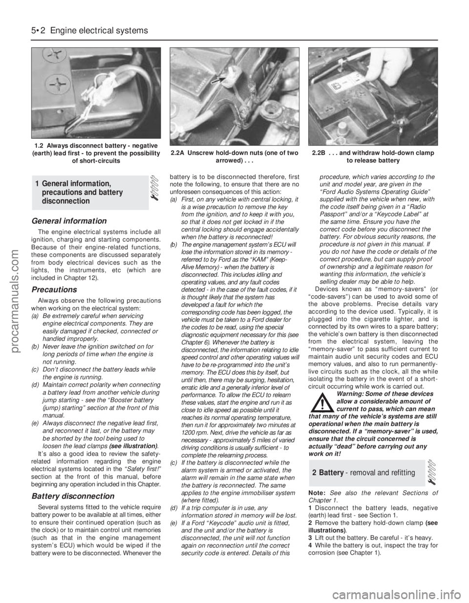
(e) Always disconnect the negative lead first,
and reconnect it last, or the battery may
be shorted by the tool being used to
loosen the lead clamps (see illustration).
It’s also a good idea to review the safety-
related information regarding the engine
electrical systems located in the “Safety first!”
section at the front of this manual, before
beginning any operation included in this Chapter.
Battery disconnection
Several systems fitted to the vehicle require
battery power to be available at all times, either
to ensure their continued operation (such as
the clock) or to maintain control unit memories
(such as that in the engine management
system’s ECU) which would be wiped if the
battery were to be disconnected. Whenever thebattery is to be disconnected therefore, first
note the following, to ensure that there are no
unforeseen consequences of this action:
(a) First, on any vehicle with central locking, it
is a wise precaution to remove the key
from the ignition, and to keep it with you,
so that it does not get locked in if the
central locking should engage accidentally
when the battery is reconnected!
(b) The engine management system’s ECU will
lose the information stored in its memory -
referred to by Ford as the “KAM” (Keep-
Alive Memory) - when the battery is
disconnected. This includes idling and
operating values, and any fault codes
detected - in the case of the fault codes, if it
is thought likely that the system has
developed a fault for which the
corresponding code has been logged, the
vehicle must be taken to a Ford dealer for
the codes to be read, using the special
diagnostic equipment necessary for this (see
Chapter 6). Whenever the battery is
disconnected, the information relating to idle
speed control and other operating values will
have to be re-programmed into the unit’s
memory. The ECU does this by itself, but
until then, there may be surging, hesitation,
erratic idle and a generally inferior level of
performance. To allow the ECU to relearn
these values, start the engine and run it as
close to idle speed as possible until it
reaches its normal operating temperature,
then run it for approximately two minutes at
1200 rpm. Next, drive the vehicle as far as
necessary - approximately 5 miles of varied
driving conditions is usually sufficient - to
complete the relearning process.
(c) If the battery is disconnected while the
alarm system is armed or activated, the
alarm will remain in the same state when
the battery is reconnected. The same
applies to the engine immobiliser system
(where fitted).
(d) If a trip computer is in use, any
information stored in memory will be lost.
(e) If a Ford “Keycode” audio unit is fitted,
and the unit and/or the battery is
disconnected, the unit will not function
again on reconnection until the correct
security code is entered. Details of thisprocedure, which varies according to the
unit and model year, are given in the
“Ford Audio Systems Operating Guide”
supplied with the vehicle when new, with
the code itself being given in a “Radio
Passport” and/or a “Keycode Label” at
the same time. Ensure you have the
correct code before you disconnect the
battery. For obvious security reasons, the
procedure is not given in this manual. If
you do not have the code or details of the
correct procedure, but can supply proof
of ownership and a legitimate reason for
wanting this information, the vehicle’s
selling dealer may be able to help.
Devices known as “memory-savers” (or
“code-savers”) can be used to avoid some of
the above problems. Precise details vary
according to the device used. Typically, it is
plugged into the cigarette lighter, and is
connected by its own wires to a spare battery;
the vehicle’s own battery is then disconnected
from the electrical system, leaving the
“memory-saver” to pass sufficient current to
maintain audio unit security codes and ECU
memory values, and also to run permanently-
live circuits such as the clock, all the while
isolating the battery in the event of a short-
circuit occurring while work is carried out.
Warning: Some of these devices
allow a considerable amount of
current to pass, which can mean
that many of the vehicle’s systems are still
operational when the main battery is
disconnected. If a “memory-saver” is used,
ensure that the circuit concerned is
actually “dead” before carrying out any
work on it!
Note:See also the relevant Sections of
Chapter 1.
1Disconnect the battery leads, negative
(earth) lead first - see Section 1.
2Remove the battery hold-down clamp (see
illustrations).
3Lift out the battery. Be careful - it’s heavy.
4While the battery is out, inspect the tray for
corrosion (see Chapter 1).
2 Battery- removal and refitting
1 General information,
precautions and battery
disconnection
5•2 Engine electrical systems
1.2 Always disconnect battery - negative
(earth) lead first - to prevent the possibility
of short-circuits2.2A Unscrew hold-down nuts (one of two
arrowed) . . .2.2B . . . and withdraw hold-down clamp
to release battery
procarmanuals.com
Page 113 of 279
5If you are renewing the battery, make sure
that you get one that’s identical, with the
same dimensions, amperage rating, cold
cranking rating, etc. Dispose of the old battery
in a responsible fashion. Most local authorities
have facilities for the collection and disposal
of such items - batteries contain sulphuric
acid and lead, and should not be simply
thrown out with the household rubbish!
6Refitting is the reverse of the removal
procedure.
Note:See also the relevant Sections of
Chapter 1.
1Periodically inspect the entire length of
each battery lead for damage, cracked or
burned insulation, and corrosion. Poor battery
lead connections can cause starting problems
and decreased engine performance.
2Check the lead-to-terminal connections at
the ends of the leads for cracks, loose wire
strands and corrosion. The presence of white,
fluffy deposits under the insulation at the lead
terminal connection is a sign that the lead is
corroded and should be renewed. Check the
terminals for distortion, missing clamp bolts,
and corrosion.
3When removing the leads, always
disconnect the negative lead first, and
reconnect it last (see Section 1). Even if only
the positive lead is being renewed, be sure to
disconnect the negative lead from the battery
first (see Chapter 1 for further information
regarding battery lead removal).
4Disconnect the old leads from the battery,
then trace each of them to their opposite
ends, and detach them from the starter
solenoid and earth terminals. Note the routing
of each lead, to ensure correct installation.
5If you are renewing either or both of the old
leads, take them with you when buying new
leads. It is vitally important that you replace
the leads with identical parts. Leads have
characteristics that make them easy to
identify: positive leads are usually red, larger
in cross-section, and have a larger-diameter
battery post clamp; earth leads are usually
black, smaller in cross-section and have a
slightly smaller-diameter clamp for the
negative post.
6Clean the threads of the solenoid or earth
connection with a wire brush to remove rust
and corrosion.
7Attach the lead to the solenoid or earth
connection, and tighten the mounting nut/bolt
securely.
8Before connecting a new lead to thebattery, make sure that it reaches the battery
post without having to be stretched.
9Connect the positive lead first, followed by
the negative lead.
General
The ignition system includes the ignition
switch, the battery, the crankshaft speed/
position sensor, the coil, the primary (low
tension/LT) and secondary (high tension/HT)
wiring circuits, and the spark plugs. On models
with automatic transmission, a separate
ignition module is also fitted, its functions
being incorporated in the ECU on models with
manual transmission. The ignition system is
controlled by the engine management
system’s Electronic Control Unit (ECU). Using
data provided by information sensors which
monitor various engine functions (such as
engine speed and piston position, intake air
mass and temperature, engine coolant
temperature, etc.), the ECU ensures a
perfectly-timed spark under all conditions (see
Chapter 6). Note:The ignition timing is under
the full control of the ECU, and cannot be
adjusted - see Section 8 for further details.
Precautions
When working on the ignition system, take
the following precautions:
(a) Do not keep the ignition switch on for more
than 10 seconds if the engine will not start.
(b) If a separate tachometer is ever required
for servicing work, consult a dealer
service department before buying a
tachometer for use with this vehicle -
some tachometers may be incompatible
with this ignition system - and always
connect it in accordance with the
equipment manufacturer’s instructions.
(c) Never connect the ignition coil terminals
to earth. This could result in damage to
the coil and/or the ECU or ignition module
(whichever is fitted).
(d) Do not disconnect the battery when the
engine is running.
(e) Make sure that the ignition module (where
fitted) is properly earthed.
(f) Refer to the warning at the beginning of
the next Section concerning HT voltage.
Warning: Because of the high
voltage generated by the ignition
system, extreme care should be
taken whenever an operation is performed
involving ignition components. This not
only includes the ignition module/ECU, coil
and spark plug (HT) leads, but related
components such as electrical connectors,
tachometer and other test equipment also.Note: This is an initial check of the “ignition
part” of the main engine management system,
to be carried out as part of the preliminary
checks of the complete engine management
system (see Chapter 6).
1If the engine turns over but won’t start,
disconnect the (HT) lead from any spark plug,
and attach it to a calibrated tester (available at
most automotive accessory shops). Connect
the clip on the tester to a good earth - a bolt
or metal bracket on the engine. If you’re
unable to obtain a calibrated ignition tester,
have the check carried out by a Ford dealer
service department or similar. Any other form
of testing (such as jumping a spark from the
end of an HT lead to earth) is not
recommended, because of the risk of
personal injury, or of damage to the
ECU/ignition module (see notes above and in
Section 4).
2Crank the engine and watch the end of the
tester to see if bright blue, well-defined sparks
occur.
3If sparks occur, sufficient voltage is
reaching the plug to fire it. Repeat the check
at the remaining plugs, to ensure that all leads
are sound and that the coil is serviceable.
However, the plugs themselves may be fouled
or faulty, so remove and check them as
described in Chapter 1.
4If no sparks or intermittent sparks occur,
the spark plug lead(s) may be defective -
check them as described in Chapter 1.
5If there’s still no spark, check the coil’s
electrical connector, to make sure it’s clean
and tight. Check for full battery voltage to the
coil at the connector’s centre terminal. The
coil is earthed through the ECU - do not
attempt to check this. Check the coil itself
(see Section 6). Make any necessary repairs,
then repeat the check again.
6The remainder of the system checks should
be left to a dealer service department or other
qualified repair facility, as there is a chance
that the ECU may be damaged if tests are not
performed properly.
Warning: Because of the high
voltage generated by the ignition
system, extreme care should be
taken whenever an operation is performed
involving ignition components. This not
only includes the ignition module/ECU, coil
and spark plug (HT) leads, but related
components such as electrical connectors,
tachometer and other test equipment also.
Check
1Having checked that full battery voltage is
available at the centre terminal of the coil’s
electrical connector (see Section 5),
disconnect the battery negative (earth) lead -
see Section 1.
2Unplug the coil’s electrical connector, if not
already disconnected.
6 Ignition coil -
removal and refitting
5 Ignition system - testing
4 Ignition system - general
information and precautions
3 Battery leads -
check and renewal
Engine electrical systems 5•3
5
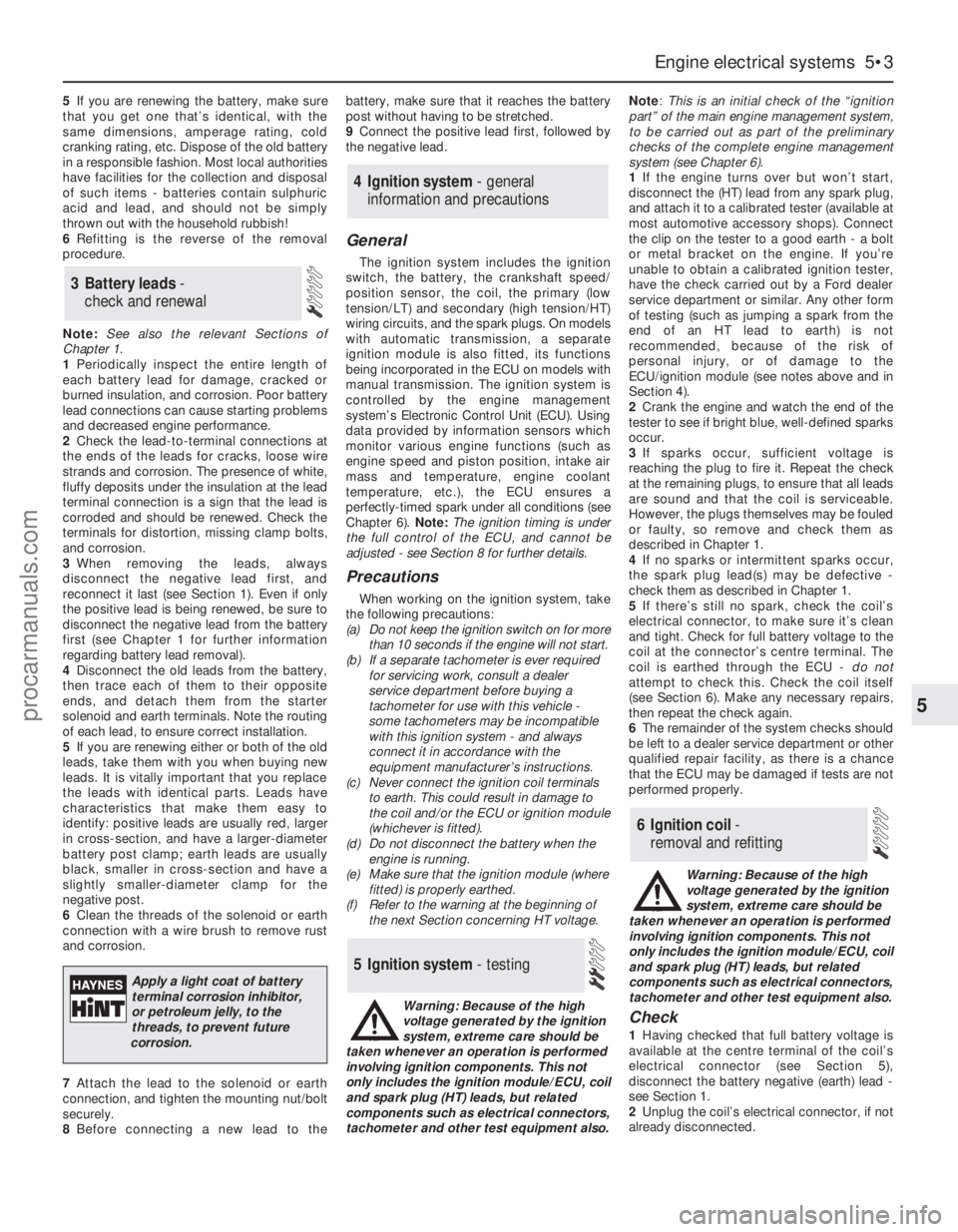
Apply a light coat of battery
terminal corrosion inhibitor,
or petroleum jelly, to the
threads, to prevent future
corrosion.
procarmanuals.com
Page 114 of 279
3Using an ohmmeter, measure the
resistance of the coil’s primary windings,
connecting the meter between the coil’s
terminal pins as follows. Measure first from
one outer pin to the centre pin, then from the
other outer pin to the centre. Compare your
readings with the coil primary resistance listed
in the Specifications Section at the beginning
of this Chapter.
4Disconnect the spark plug (HT) leads - note
their connections or label them carefully, as
described in Chapter 1. Use the meter to
check that there is continuity (ie, a resistance
corresponding to that of the coil secondary
winding) between each pair of (HT) lead
terminals; Nos 1 and 4 terminals are
connected by their secondary winding, as are
Nos 2 and 3. Now switch to the highest
resistance scale, and check that there is no
continuity between either pair of terminals and
the other - ie, there should be infinite
resistance between terminals 1 and 2, or 4
and 3 - and between any terminal and earth.
5If either of the above tests yield resistance
values outside the specified amount, or
results other than those described, renew the
coil. Any further testing should be left to a
dealer service department or other qualified
repair facility.
Removal and refitting
6Disconnect the battery negative (earth) lead
- see Section 1.
7Remove the air mass meter and resonator -
refer to Chapter 4.
8Unplug the electrical connector from each
side of the coil, then disconnect the spark
plug (HT) leads - note their connections or
label them carefully, as described in Chapter
1.
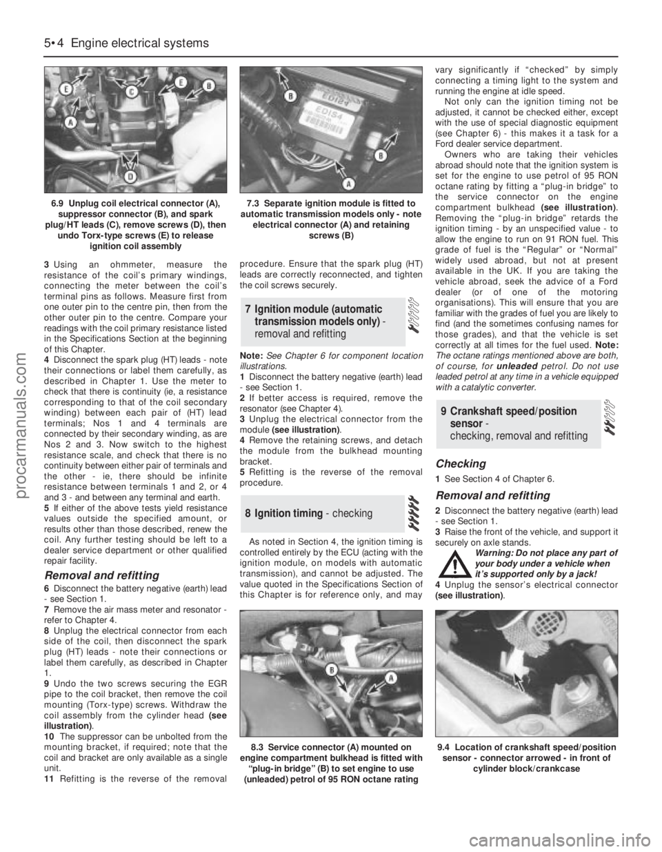
9Undo the two screws securing the EGR
pipe to the coil bracket, then remove the coil
mounting (Torx-type) screws. Withdraw the
coil assembly from the cylinder head (see
illustration).
10The suppressor can be unbolted from the
mounting bracket, if required; note that the
coil and bracket are only available as a single
unit.
11Refitting is the reverse of the removalprocedure. Ensure that the spark plug (HT)
leads are correctly reconnected, and tighten
the coil screws securely.
Note:See Chapter 6 for component location
illustrations.
1Disconnect the battery negative (earth) lead
- see Section 1.
2If better access is required, remove the
resonator (see Chapter 4).
3Unplug the electrical connector from the
module (see illustration).
4Remove the retaining screws, and detach
the module from the bulkhead mounting
bracket.
5Refitting is the reverse of the removal
procedure.
As noted in Section 4, the ignition timing is
controlled entirely by the ECU (acting with the
ignition module, on models with automatic
transmission), and cannot be adjusted. The
value quoted in the Specifications Section of
this Chapter is for reference only, and mayvary significantly if “checked” by simply
connecting a timing light to the system and
running the engine at idle speed.
Not only can the ignition timing not be
adjusted, it cannot be checked either, except
with the use of special diagnostic equipment
(see Chapter 6) - this makes it a task for a
Ford dealer service department.
Owners who are taking their vehicles
abroad should note that the ignition system is
set for the engine to use petrol of 95 RON
octane rating by fitting a “plug-in bridge” to
the service connector on the engine
compartment bulkhead (see illustration).
Removing the “plug-in bridge” retards the
ignition timing - by an unspecified value - to
allow the engine to run on 91 RON fuel. This
grade of fuel is the “Regular” or “Normal”
widely used abroad, but not at present
available in the UK. If you are taking the
vehicle abroad, seek the advice of a Ford
dealer (or of one of the motoring
organisations). This will ensure that you are
familiar with the grades of fuel you are likely to
find (and the sometimes confusing names for
those grades), and that the vehicle is set
correctly at all times for the fuel used. Note:
The octane ratings mentioned above are both,
of course, for unleadedpetrol. Do not use
leaded petrol at any time in a vehicle equipped
with a catalytic converter.
Checking
1See Section 4 of Chapter 6.
Removal and refitting
2Disconnect the battery negative (earth) lead
- see Section 1.
3Raise the front of the vehicle, and support it
securely on axle stands.
Warning: Do not place any part of
your body under a vehicle when
it’s supported only by a jack!
4Unplug the sensor’s electrical connector
(see illustration).
9 Crankshaft speed/position
sensor-
checking, removal and refitting
8 Ignition timing - checking
7 Ignition module (automatic
transmission models only) -
removal and refitting
5•4 Engine electrical systems
6.9 Unplug coil electrical connector (A),
suppressor connector (B), and spark
plug/HT leads (C), remove screws (D), then
undo Torx-type screws (E) to release
ignition coil assembly7.3 Separate ignition module is fitted to
automatic transmission models only - note
electrical connector (A) and retaining
screws (B)
8.3 Service connector (A) mounted on
engine compartment bulkhead is fitted with
“plug-in bridge” (B) to set engine to use
(unleaded) petrol of 95 RON octane rating9.4 Location of crankshaft speed/position
sensor - connector arrowed - in front of
cylinder block/crankcase
procarmanuals.com
Page 116 of 279
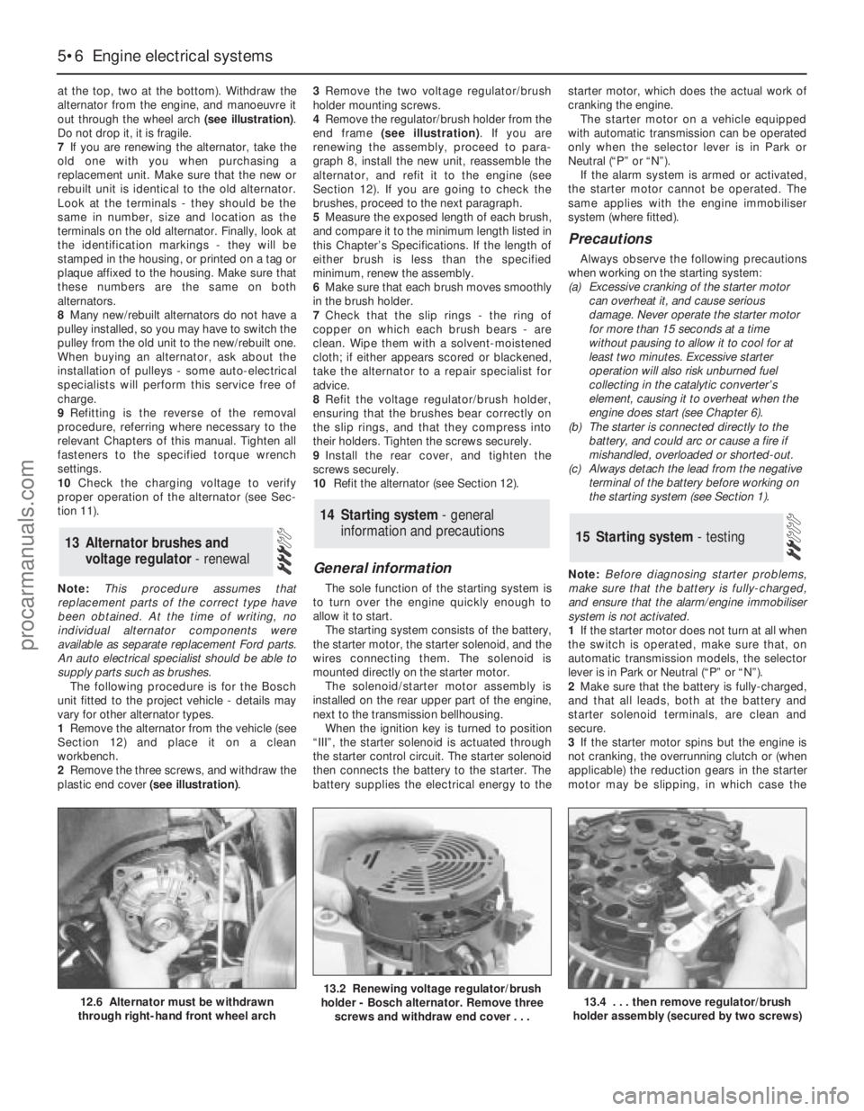
at the top, two at the bottom). Withdraw the
alternator from the engine, and manoeuvre it
out through the wheel arch (see illustration).
Do not drop it, it is fragile.
7If you are renewing the alternator, take the
old one with you when purchasing a
replacement unit. Make sure that the new or
rebuilt unit is identical to the old alternator.
Look at the terminals - they should be the
same in number, size and location as the
terminals on the old alternator. Finally, look at
the identification markings - they will be
stamped in the housing, or printed on a tag or
plaque affixed to the housing. Make sure that
these numbers are the same on both
alternators.
8Many new/rebuilt alternators do not have a
pulley installed, so you may have to switch the
pulley from the old unit to the new/rebuilt one.
When buying an alternator, ask about the
installation of pulleys - some auto-electrical
specialists will perform this service free of
charge.
9Refitting is the reverse of the removal
procedure, referring where necessary to the
relevant Chapters of this manual. Tighten all
fasteners to the specified torque wrench
settings.
10Check the charging voltage to verify
proper operation of the alternator (see Sec-
tion 11).
Note:This procedure assumes that
replacement parts of the correct type have
been obtained. At the time of writing, no
individual alternator components were
available as separate replacement Ford parts.
An auto electrical specialist should be able to
supply parts such as brushes.
The following procedure is for the Bosch
unit fitted to the project vehicle - details may
vary for other alternator types.
1Remove the alternator from the vehicle (see
Section 12) and place it on a clean
workbench.
2Remove the three screws, and withdraw the
plastic end cover (see illustration).3Remove the two voltage regulator/brush
holder mounting screws.
4Remove the regulator/brush holder from the
end frame (see illustration). If you are
renewing the assembly, proceed to para-
graph 8, install the new unit, reassemble the
alternator, and refit it to the engine (see
Section 12). If you are going to check the
brushes, proceed to the next paragraph.
5Measure the exposed length of each brush,
and compare it to the minimum length listed in
this Chapter’s Specifications. If the length of
either brush is less than the specified
minimum, renew the assembly.
6Make sure that each brush moves smoothly
in the brush holder.
7Check that the slip rings - the ring of
copper on which each brush bears - are
clean. Wipe them with a solvent-moistened
cloth; if either appears scored or blackened,
take the alternator to a repair specialist for
advice.
8Refit the voltage regulator/brush holder,
ensuring that the brushes bear correctly on
the slip rings, and that they compress into
their holders. Tighten the screws securely.
9Install the rear cover, and tighten the
screws securely.
10Refit the alternator (see Section 12).
General information
The sole function of the starting system is
to turn over the engine quickly enough to
allow it to start.
The starting system consists of the battery,
the starter motor, the starter solenoid, and the
wires connecting them. The solenoid is
mounted directly on the starter motor.
The solenoid/starter motor assembly is
installed on the rear upper part of the engine,
next to the transmission bellhousing.
When the ignition key is turned to position
“III”, the starter solenoid is actuated through
the starter control circuit. The starter solenoid
then connects the battery to the starter. The
battery supplies the electrical energy to thestarter motor, which does the actual work of
cranking the engine.
The starter motor on a vehicle equipped
with automatic transmission can be operated
only when the selector lever is in Park or
Neutral (“P” or “N”).
If the alarm system is armed or activated,
the starter motor cannot be operated. The
same applies with the engine immobiliser
system (where fitted).
Precautions
Always observe the following precautions
when working on the starting system:
(a) Excessive cranking of the starter motor
can overheat it, and cause serious
damage. Never operate the starter motor
for more than 15 seconds at a time
without pausing to allow it to cool for at
least two minutes. Excessive starter
operation will also risk unburned fuel
collecting in the catalytic converter’s
element, causing it to overheat when the
engine does start (see Chapter 6).
(b) The starter is connected directly to the
battery, and could arc or cause a fire if
mishandled, overloaded or shorted-out.
(c) Always detach the lead from the negative
terminal of the battery before working on
the starting system (see Section 1).
Note:Before diagnosing starter problems,
make sure that the battery is fully-charged,
and ensure that the alarm/engine immobiliser
system is not activated.
1If the starter motor does not turn at all when
the switch is operated, make sure that, on
automatic transmission models, the selector
lever is in Park or Neutral (“P” or “N”).
2Make sure that the battery is fully-charged,
and that all leads, both at the battery and
starter solenoid terminals, are clean and
secure.
3If the starter motor spins but the engine is
not cranking, the overrunning clutch or (when
applicable) the reduction gears in the starter
motor may be slipping, in which case the
15 Starting system - testing
14 Starting system - general
information and precautions
13 Alternator brushes and
voltage regulator - renewal
5•6 Engine electrical systems
12.6 Alternator must be withdrawn
through right-hand front wheel arch13.2 Renewing voltage regulator/brush
holder - Bosch alternator. Remove three
screws and withdraw end cover . . .13.4 . . . then remove regulator/brush
holder assembly (secured by two screws)
procarmanuals.com
Page 117 of 279
starter motor must be overhauled or renewed.
(Other possibilities are that the starter motor
mounting bolts are very loose, or that teeth
are missing from the flywheel/driveplate ring
gear.)
4If, when the switch is actuated, the starter
motor does not operate at all but the solenoid
clicks, then the problem lies with either the
battery, the main solenoid contacts, or the
starter motor itself (or the engine is seized).
5If the solenoid plunger cannot be heard to
click when the switch is actuated, the battery
is faulty, there is a fault in the circuit, or the
solenoid itself is defective.
6To check the solenoid, connect a fused
jumper lead between the battery (+) and the
ignition switch terminal (the small terminal) on
the solenoid. If the starter motor now
operates, the solenoid is OK, and the problem
is in the ignition switch, selector lever position
sensor (automatic transmission) or in the
wiring.
7If the starter motor still does not operate,
remove it (see Section 16). The brushes and
commutator may be checked (see Sec-
tion 17), but if the fault persists, the motor
should be renewed, or taken to an auto-
electrician for testing and repair.
8If the starter motor cranks the engine at anabnormally-slow speed, first make sure that
the battery is charged, and that all terminal
connections are tight. If the engine is partially
seized, or has the wrong viscosity oil in it, it
will crank slowly.
9Run the engine until normal operating
temperature is reached, then switch off and
disable the ignition system by unplugging the
ignition coil’s electrical connector; remove
fuse 14 to disconnect the fuel pump.
10Connect a voltmeter positive lead to the
battery positive terminal, and connect the
negative lead to the negative terminal.
11Crank the engine, and take the voltmeter
readings as soon as a steady figure is
indicated. Do not allow the starter motor to
turn for more than 15 seconds at a time. A
reading of 10.5 volts or more, with the starter
motor turning at normal cranking speed, is
normal. If the reading is 10.5 volts or more but
the cranking speed is slow, the solenoid
contacts are burned, the motor is faulty, or
there is a bad connection. If the reading is less
than 10.5 volts and the cranking speed is
slow, the starter motor is faulty or there is a
problem with the battery.1Disconnect the battery negative (earth) lead
- see Section 1.
2Remove the air mass meter and resonator -
refer to Chapter 4.
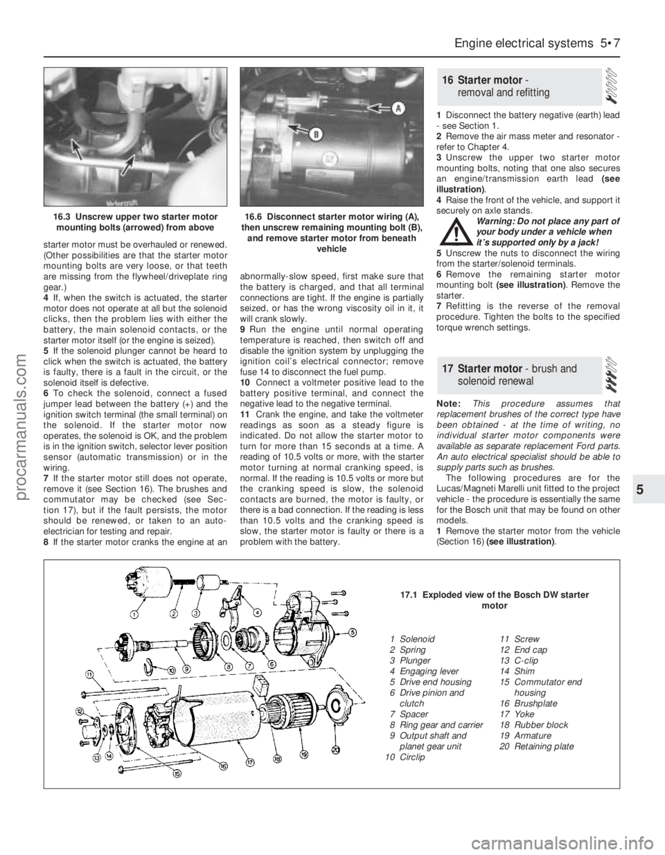
3Unscrew the upper two starter motor
mounting bolts, noting that one also secures
an engine/transmission earth lead (see
illustration).
4Raise the front of the vehicle, and support it
securely on axle stands.
Warning: Do not place any part of
your body under a vehicle when
it’s supported only by a jack!
5Unscrew the nuts to disconnect the wiring
from the starter/solenoid terminals.
6Remove the remaining starter motor
mounting bolt (see illustration). Remove the
starter.
7Refitting is the reverse of the removal
procedure. Tighten the bolts to the specified
torque wrench settings.
Note:This procedure assumes that
replacement brushes of the correct type have
been obtained - at the time of writing, no
individual starter motor components were
available as separate replacement Ford parts.
An auto electrical specialist should be able to
supply parts such as brushes.
The following procedures are for the
Lucas/Magneti Marelli unit fitted to the project
vehicle - the procedure is essentially the same
for the Bosch unit that may be found on other
models.
1Remove the starter motor from the vehicle
(Section 16) (see illustration).
17 Starter motor- brush and
solenoid renewal
16 Starter motor -
removal and refitting
Engine electrical systems 5•7
5
16.3 Unscrew upper two starter motor
mounting bolts (arrowed) from above16.6 Disconnect starter motor wiring (A),
then unscrew remaining mounting bolt (B),
and remove starter motor from beneath
vehicle
17.1 Exploded view of the Bosch DW starter
motor
1 Solenoid
2 Spring
3 Plunger
4 Engaging lever
5 Drive end housing
6 Drive pinion and
clutch
7 Spacer
8 Ring gear and carrier
9 Output shaft and
planet gear unit
10 Circlip11 Screw
12 End cap
13 C-clip
14 Shim
15 Commutator end
housing
16 Brushplate
17 Yoke
18 Rubber block
19 Armature
20 Retaining plate
procarmanuals.com
Page 120 of 279
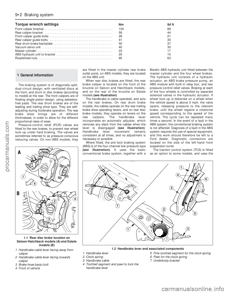
Torque wrench settingsNm lbf ft
Front caliper bracket . . . . . . . . . . . . . . . . . . . . . . . . . . . . . . . . . . . . . . . . 120 89
Rear caliper bracket . . . . . . . . . . . . . . . . . . . . . . . . . . . . . . . . . . . . . . . . 59 44
Front caliper guide bolts . . . . . . . . . . . . . . . . . . . . . . . . . . . . . . . . . . . . . 28 21
Rear caliper guide bolts . . . . . . . . . . . . . . . . . . . . . . . . . . . . . . . . . . . . . 41 30
Rear drum brake backplate . . . . . . . . . . . . . . . . . . . . . . . . . . . . . . . . . . . 50 37
Vacuum servo unit . . . . . . . . . . . . . . . . . . . . . . . . . . . . . . . . . . . . . . . . . 40 30
Master cylinder . . . . . . . . . . . . . . . . . . . . . . . . . . . . . . . . . . . . . . . . . . . . 23 17
ABS hydraulic unit to bracket . . . . . . . . . . . . . . . . . . . . . . . . . . . . . . . . . 20 15
Roadwheel nuts . . . . . . . . . . . . . . . . . . . . . . . . . . . . . . . . . . . . . . . . . . . 85 63
9•2 Braking system
1.2 Handbrake lever and associated components
1 Handbrake lever
2 Clock spring
3 Handbrake cable
4 Toothed segment and pawl to lock the
handbrake lever5 Fine-toothed segment for the clock spring
6 Pawl for the clock spring
7 Underbody bracket
The braking system is of diagonally-split,
dual-circuit design, with ventilated discs at
the front, and drum or disc brakes (according
to model) at the rear. The front calipers are of
floating single-piston design, using asbestos-
free pads. The rear drum brakes are of the
leading and trailing shoe type. They are self-
adjusting during footbrake operation. The rear
brake shoe linings are of different
thicknesses, in order to allow for the different
proportional rates of wear.
Pressure-control relief (PCR) valves are
fitted to the rear brakes, to prevent rear wheel
lock-up under hard braking. The valves are
sometimes referred to as pressure-conscious
reducing valves. On non-ABS models, theyare fitted in the master cylinder rear brake
outlet ports; on ABS models, they are located
on the ABS unit.
When rear disc brakes are fitted, the rear
brake caliper is located on the front of the
knuckle on Saloon and Hatchback models,
and on the rear of the knuckle on Estate
models (see illustration).
The handbrake is cable-operated, and acts
on the rear brakes. On rear drum brake
models, the cables operate on the rear trailing
brake shoe operating levers, and on rear disc
brake models, they operate on levers on the
rear calipers. The handbrake lever
incorporates an automatic adjuster, which
removes any slack from the cables when the
lever is disengaged (see illustration).
Handbrake lever movement remains
consistent at all times, and no adjustment is
necessary or possible.
Where fitted, the anti-lock braking system
(ABS) is of the four-channel low-pressure type
(see illustration). It uses the basic
conventional brake system, together with aBendix ABS hydraulic unit fitted between the
master cylinder and the four wheel brakes.
The hydraulic unit consists of a hydraulic
actuator, an ABS brake pressure pump, an
ABS module with built-in relay box, and two
pressure-control relief valves. Braking at each
of the four wheels is controlled by separate
solenoid valves in the hydraulic actuator. If
wheel lock-up is detected on a wheel when
the vehicle speed is above 3 mph, the valve
opens, releasing pressure to the relevant
brake, until the wheel regains a rotational
speed corresponding to the speed of the
vehicle. The cycle can be repeated many
times a second. In the event of a fault in the
ABS system, the conventional braking system
is not affected. Diagnosis of a fault in the ABS
system requires the use of special equipment,
and this work should therefore be left to a
Ford dealer. Diagnostic connectors are
located on the side of the left-hand front
suspension turret.
The traction control system (TCS) is fitted
as an option to some models, and uses the
1 General information
1.1 Rear disc brake location on
Saloon/Hatchback models (A) and Estate
models (B)
1 Handbrake cable lever facing away from
caliper
2 Handbrake cable lever facing towards
caliper
3 Brake hose banjo bolt
4 Front of vehicle
procarmanuals.com