catalytic converter FORD MONDEO 1993 Service User Guide
[x] Cancel search | Manufacturer: FORD, Model Year: 1993, Model line: MONDEO, Model: FORD MONDEO 1993Pages: 279, PDF Size: 12.71 MB
Page 114 of 279
3Using an ohmmeter, measure the
resistance of the coil’s primary windings,
connecting the meter between the coil’s
terminal pins as follows. Measure first from
one outer pin to the centre pin, then from the
other outer pin to the centre. Compare your
readings with the coil primary resistance listed
in the Specifications Section at the beginning
of this Chapter.
4Disconnect the spark plug (HT) leads - note
their connections or label them carefully, as
described in Chapter 1. Use the meter to
check that there is continuity (ie, a resistance
corresponding to that of the coil secondary
winding) between each pair of (HT) lead
terminals; Nos 1 and 4 terminals are
connected by their secondary winding, as are
Nos 2 and 3. Now switch to the highest
resistance scale, and check that there is no
continuity between either pair of terminals and
the other - ie, there should be infinite
resistance between terminals 1 and 2, or 4
and 3 - and between any terminal and earth.
5If either of the above tests yield resistance
values outside the specified amount, or
results other than those described, renew the
coil. Any further testing should be left to a
dealer service department or other qualified
repair facility.
Removal and refitting
6Disconnect the battery negative (earth) lead
- see Section 1.
7Remove the air mass meter and resonator -
refer to Chapter 4.
8Unplug the electrical connector from each
side of the coil, then disconnect the spark
plug (HT) leads - note their connections or
label them carefully, as described in Chapter
1.
9Undo the two screws securing the EGR
pipe to the coil bracket, then remove the coil
mounting (Torx-type) screws. Withdraw the
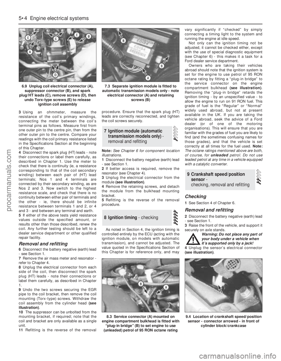
coil assembly from the cylinder head (see
illustration).
10The suppressor can be unbolted from the
mounting bracket, if required; note that the
coil and bracket are only available as a single
unit.
11Refitting is the reverse of the removalprocedure. Ensure that the spark plug (HT)
leads are correctly reconnected, and tighten
the coil screws securely.
Note:See Chapter 6 for component location
illustrations.
1Disconnect the battery negative (earth) lead
- see Section 1.
2If better access is required, remove the
resonator (see Chapter 4).
3Unplug the electrical connector from the
module (see illustration).
4Remove the retaining screws, and detach
the module from the bulkhead mounting
bracket.
5Refitting is the reverse of the removal
procedure.
As noted in Section 4, the ignition timing is
controlled entirely by the ECU (acting with the
ignition module, on models with automatic
transmission), and cannot be adjusted. The
value quoted in the Specifications Section of
this Chapter is for reference only, and mayvary significantly if “checked” by simply
connecting a timing light to the system and
running the engine at idle speed.
Not only can the ignition timing not be
adjusted, it cannot be checked either, except
with the use of special diagnostic equipment
(see Chapter 6) - this makes it a task for a
Ford dealer service department.
Owners who are taking their vehicles
abroad should note that the ignition system is
set for the engine to use petrol of 95 RON
octane rating by fitting a “plug-in bridge” to
the service connector on the engine
compartment bulkhead (see illustration).
Removing the “plug-in bridge” retards the
ignition timing - by an unspecified value - to
allow the engine to run on 91 RON fuel. This
grade of fuel is the “Regular” or “Normal”
widely used abroad, but not at present
available in the UK. If you are taking the
vehicle abroad, seek the advice of a Ford
dealer (or of one of the motoring
organisations). This will ensure that you are
familiar with the grades of fuel you are likely to
find (and the sometimes confusing names for
those grades), and that the vehicle is set
correctly at all times for the fuel used. Note:
The octane ratings mentioned above are both,
of course, for unleadedpetrol. Do not use
leaded petrol at any time in a vehicle equipped
with a catalytic converter.
Checking
1See Section 4 of Chapter 6.
Removal and refitting
2Disconnect the battery negative (earth) lead
- see Section 1.
3Raise the front of the vehicle, and support it
securely on axle stands.
Warning: Do not place any part of
your body under a vehicle when
it’s supported only by a jack!
4Unplug the sensor’s electrical connector
(see illustration).
9 Crankshaft speed/position
sensor-
checking, removal and refitting
8 Ignition timing - checking
7 Ignition module (automatic
transmission models only) -
removal and refitting
5•4 Engine electrical systems
6.9 Unplug coil electrical connector (A),
suppressor connector (B), and spark
plug/HT leads (C), remove screws (D), then
undo Torx-type screws (E) to release
ignition coil assembly7.3 Separate ignition module is fitted to
automatic transmission models only - note
electrical connector (A) and retaining
screws (B)
8.3 Service connector (A) mounted on
engine compartment bulkhead is fitted with
“plug-in bridge” (B) to set engine to use
(unleaded) petrol of 95 RON octane rating9.4 Location of crankshaft speed/position
sensor - connector arrowed - in front of
cylinder block/crankcase
procarmanuals.com
Page 116 of 279
at the top, two at the bottom). Withdraw the
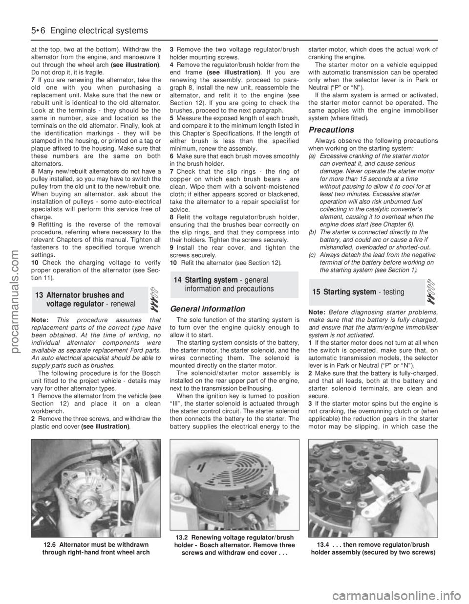
alternator from the engine, and manoeuvre it
out through the wheel arch (see illustration).
Do not drop it, it is fragile.
7If you are renewing the alternator, take the
old one with you when purchasing a
replacement unit. Make sure that the new or
rebuilt unit is identical to the old alternator.
Look at the terminals - they should be the
same in number, size and location as the
terminals on the old alternator. Finally, look at
the identification markings - they will be
stamped in the housing, or printed on a tag or
plaque affixed to the housing. Make sure that
these numbers are the same on both
alternators.
8Many new/rebuilt alternators do not have a
pulley installed, so you may have to switch the
pulley from the old unit to the new/rebuilt one.
When buying an alternator, ask about the
installation of pulleys - some auto-electrical
specialists will perform this service free of
charge.
9Refitting is the reverse of the removal
procedure, referring where necessary to the
relevant Chapters of this manual. Tighten all
fasteners to the specified torque wrench
settings.
10Check the charging voltage to verify
proper operation of the alternator (see Sec-
tion 11).
Note:This procedure assumes that
replacement parts of the correct type have
been obtained. At the time of writing, no
individual alternator components were
available as separate replacement Ford parts.
An auto electrical specialist should be able to
supply parts such as brushes.
The following procedure is for the Bosch
unit fitted to the project vehicle - details may
vary for other alternator types.
1Remove the alternator from the vehicle (see
Section 12) and place it on a clean
workbench.
2Remove the three screws, and withdraw the
plastic end cover (see illustration).3Remove the two voltage regulator/brush
holder mounting screws.
4Remove the regulator/brush holder from the
end frame (see illustration). If you are
renewing the assembly, proceed to para-
graph 8, install the new unit, reassemble the
alternator, and refit it to the engine (see
Section 12). If you are going to check the
brushes, proceed to the next paragraph.
5Measure the exposed length of each brush,
and compare it to the minimum length listed in
this Chapter’s Specifications. If the length of
either brush is less than the specified
minimum, renew the assembly.
6Make sure that each brush moves smoothly
in the brush holder.
7Check that the slip rings - the ring of
copper on which each brush bears - are
clean. Wipe them with a solvent-moistened
cloth; if either appears scored or blackened,
take the alternator to a repair specialist for
advice.
8Refit the voltage regulator/brush holder,
ensuring that the brushes bear correctly on
the slip rings, and that they compress into
their holders. Tighten the screws securely.
9Install the rear cover, and tighten the
screws securely.
10Refit the alternator (see Section 12).
General information
The sole function of the starting system is
to turn over the engine quickly enough to
allow it to start.
The starting system consists of the battery,
the starter motor, the starter solenoid, and the
wires connecting them. The solenoid is
mounted directly on the starter motor.
The solenoid/starter motor assembly is
installed on the rear upper part of the engine,
next to the transmission bellhousing.
When the ignition key is turned to position
“III”, the starter solenoid is actuated through
the starter control circuit. The starter solenoid
then connects the battery to the starter. The
battery supplies the electrical energy to thestarter motor, which does the actual work of
cranking the engine.
The starter motor on a vehicle equipped
with automatic transmission can be operated
only when the selector lever is in Park or
Neutral (“P” or “N”).
If the alarm system is armed or activated,
the starter motor cannot be operated. The
same applies with the engine immobiliser
system (where fitted).
Precautions
Always observe the following precautions
when working on the starting system:
(a) Excessive cranking of the starter motor
can overheat it, and cause serious
damage. Never operate the starter motor
for more than 15 seconds at a time
without pausing to allow it to cool for at
least two minutes. Excessive starter
operation will also risk unburned fuel
collecting in the catalytic converter’s
element, causing it to overheat when the
engine does start (see Chapter 6).
(b) The starter is connected directly to the
battery, and could arc or cause a fire if
mishandled, overloaded or shorted-out.
(c) Always detach the lead from the negative
terminal of the battery before working on
the starting system (see Section 1).
Note:Before diagnosing starter problems,
make sure that the battery is fully-charged,
and ensure that the alarm/engine immobiliser
system is not activated.
1If the starter motor does not turn at all when
the switch is operated, make sure that, on
automatic transmission models, the selector
lever is in Park or Neutral (“P” or “N”).
2Make sure that the battery is fully-charged,
and that all leads, both at the battery and
starter solenoid terminals, are clean and
secure.
3If the starter motor spins but the engine is
not cranking, the overrunning clutch or (when
applicable) the reduction gears in the starter
motor may be slipping, in which case the
15 Starting system - testing
14 Starting system - general
information and precautions
13 Alternator brushes and
voltage regulator - renewal
5•6 Engine electrical systems
12.6 Alternator must be withdrawn
through right-hand front wheel arch13.2 Renewing voltage regulator/brush
holder - Bosch alternator. Remove three
screws and withdraw end cover . . .13.4 . . . then remove regulator/brush
holder assembly (secured by two screws)
procarmanuals.com
Page 135 of 279
Chapter 6 Emissions control systems
Catalytic converter - general information, checking
and component renewal . . . . . . . . . . . . . . . . . . . . . . . . . . . . . . . . 9
Diagnosis system - general information . . . . . . . . . . . . . . . . . . . . . . 3
Electronic control system - description and precautions . . . . . . . . . 2
Engine compartment wiring check . . . . . . . . . . . . . . . See Chapter 1
EVAPorative emissions control (EVAP) system - general
information, checking and component renewal . . . . . . . . . . . . . . 5
Exhaust Gas Recirculation (EGR) system - general
information, checking and component renewal . . . . . . . . . . . . . . 6
Exhaust system check . . . . . . . . . . . . . . . . . . . . . . . . . See Chapter 1General information . . . . . . . . . . . . . . . . . . . . . . . . . . . . . . . . . . . . . . 1
Information sensors - general information, testing,
removal and refitting . . . . . . . . . . . . . . . . . . . . . . . . . . . . . . . . . . . 4
Positive Crankcase Ventilation (PCV) system - general
information, checking and component renewal . . . . . . . . . . . . . . 8
Positive Crankcase Ventilation (PCV) system check
and filter cleaning . . . . . . . . . . . . . . . . . . . . . . . . . . . . . See Chapter 1
Pulse-air system - general information, checking
and component renewal . . . . . . . . . . . . . . . . . . . . . . . . . . . . . . . . 7
Underbonnet hose check . . . . . . . . . . . . . . . . . . . . . . . See Chapter 1
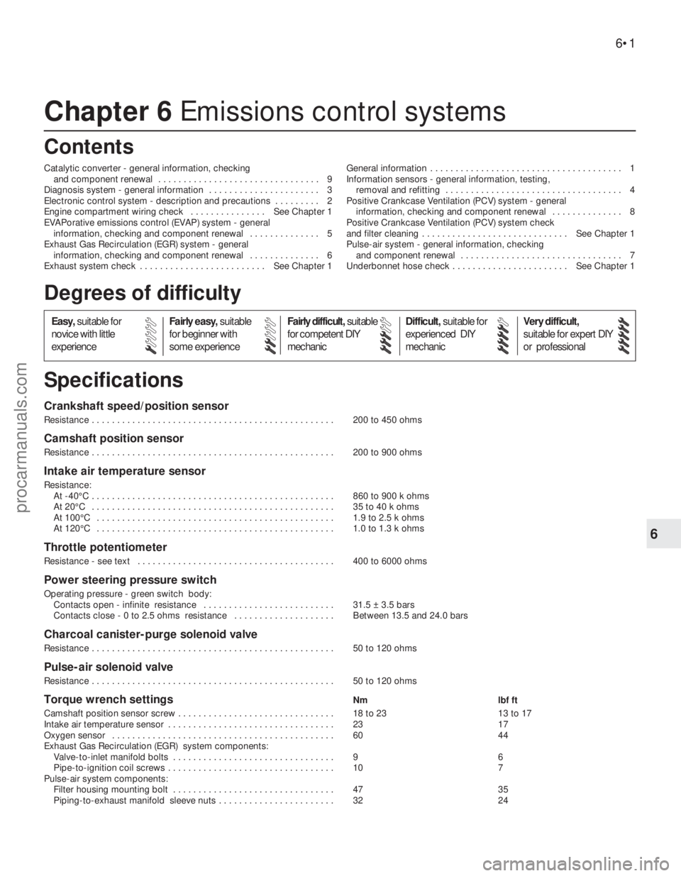
Crankshaft speed/position sensor
Resistance . . . . . . . . . . . . . . . . . . . . . . . . . . . . . . . . . . . . . . . . . . . . . . . . 200 to 450 ohms
Camshaft position sensor
Resistance . . . . . . . . . . . . . . . . . . . . . . . . . . . . . . . . . . . . . . . . . . . . . . . . 200 to 900 ohms
Intake air temperature sensor
Resistance:
At -40°C . . . . . . . . . . . . . . . . . . . . . . . . . . . . . . . . . . . . . . . . . . . . . . . . 860 to 900 k ohms
At 20°C . . . . . . . . . . . . . . . . . . . . . . . . . . . . . . . . . . . . . . . . . . . . . . . . 35 to 40 k ohms
At 100°C . . . . . . . . . . . . . . . . . . . . . . . . . . . . . . . . . . . . . . . . . . . . . . . 1.9 to 2.5 k ohms
At 120°C . . . . . . . . . . . . . . . . . . . . . . . . . . . . . . . . . . . . . . . . . . . . . . . 1.0 to 1.3 k ohms
Throttle potentiometer
Resistance - see text . . . . . . . . . . . . . . . . . . . . . . . . . . . . . . . . . . . . . . . 400 to 6000 ohms
Power steering pressure switch
Operating pressure - green switch body:
Contacts open - infinite resistance . . . . . . . . . . . . . . . . . . . . . . . . . . 31.5 ± 3.5 bars
Contacts close - 0 to 2.5 ohms resistance . . . . . . . . . . . . . . . . . . . . Between 13.5 and 24.0 bars
Charcoal canister-purge solenoid valve
Resistance . . . . . . . . . . . . . . . . . . . . . . . . . . . . . . . . . . . . . . . . . . . . . . . . 50 to 120 ohms
Pulse-air solenoid valve
Resistance . . . . . . . . . . . . . . . . . . . . . . . . . . . . . . . . . . . . . . . . . . . . . . . . 50 to 120 ohms
Torque wrench settingsNm lbf ft
Camshaft position sensor screw . . . . . . . . . . . . . . . . . . . . . . . . . . . . . . . 18 to 23 13 to 17
Intake air temperature sensor . . . . . . . . . . . . . . . . . . . . . . . . . . . . . . . . . 23 17
Oxygen sensor . . . . . . . . . . . . . . . . . . . . . . . . . . . . . . . . . . . . . . . . . . . . 60 44
Exhaust Gas Recirculation (EGR) system components:
Valve-to-inlet manifold bolts . . . . . . . . . . . . . . . . . . . . . . . . . . . . . . . . 9 6
Pipe-to-ignition coil screws . . . . . . . . . . . . . . . . . . . . . . . . . . . . . . . . . 10 7
Pulse-air system components:
Filter housing mounting bolt . . . . . . . . . . . . . . . . . . . . . . . . . . . . . . . . 47 35
Piping-to-exhaust manifold sleeve nuts . . . . . . . . . . . . . . . . . . . . . . . 32 24
6•1
Easy,suitable for
novice with little
experienceFairly easy,suitable
for beginner with
some experienceFairly difficult,suitable
for competent DIY
mechanicDifficult,suitable for
experienced DIY
mechanicVery difficult,
suitable for expert DIY
or professional
Degrees of difficulty
Specifications Contents
6
procarmanuals.com
Page 136 of 279
To minimise pollution of the atmosphere
from incompletely-burned and evaporating
gases, and to maintain good driveability and
fuel economy, a number of emission control
systems are used on these vehicles. They
include the following:
(a) The engine management system
(comprising both fuel and ignition sub-
systems) itself.
(b) Positive Crankcase Ventilation (PCV)
system.
(c) Evaporative Emissions Control (EVAP)
system.
(d) Exhaust Gas Recirculation (EGR) system.
(e) Catalytic converter.
The Sections of this Chapter include
general descriptions, checking procedures
within the scope of the home mechanic, and
component renewal procedures (when
possible) for each of the systems listed above.
Before assuming an emissions control system
is malfunctioning, check the fuel and ignition
systems carefully (see Chapters 4 and 5). The
diagnosis of some emission control devices
requires specialised tools, equipment and
training. If checking and servicing become too
difficult, or if a procedure is beyond the scope ofyour skills, consult your dealer service
department or other specialist.
This doesn’t mean, however, that emission
control systems are particularly difficult to
maintain and repair. You can quickly and
easily perform many checks, and do most of
the regular maintenance, at home with
common tune-up and hand tools. Note:The
most frequent cause of emissions problems is
simply a loose or broken electrical connector
or vacuum hose, so always check the
electrical connectors and vacuum hoses first.
Pay close attention to any special
precautions outlined in this Chapter. It should
be noted that the illustrations of the various
systems may not exactly match the system
installed on your vehicle, due to changes
made by the manufacturer during production
or from year-to-year.
Vehicles sold in some areas will carry a
Vehicle Emissions Control Information (VECI)
label, and a vacuum hose diagram located in
the engine compartment. These contain
important specifications and setting
procedures for the various emissions control
systems, with the vacuum hose diagram
identifying emissions control components.
When servicing the engine or emissions
systems, the VECI label in your particular
vehicle should always be checked for up-to-
date information.Description
The EEC-IV (Ford’s fourth-generation
Electronic Engine Control system) engine
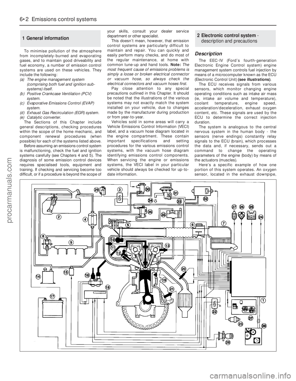
management system controls fuel injection by
means of a microcomputer known as the ECU
(Electronic Control Unit) (see illustrations).
The ECU receives signals from various
sensors, which monitor changing engine
operating conditions such as intake air mass
(ie, intake air volume and temperature),
coolant temperature, engine speed,
acceleration/deceleration, exhaust oxygen
content, etc. These signals are used by the
ECU to determine the correct injection
duration.
The system is analogous to the central
nervous system in the human body - the
sensors (nerve endings) constantly relay
signals to the ECU (brain), which processes
the data and, if necessary, sends out a
command to change the operating
parameters of the engine (body) by means of
the actuators (muscles).
Here’s a specific example of how one
portion of this system operates. An oxygen
sensor, located in the exhaust downpipe,
2 Electronic control system -
description and precautions1 General information
6•2 Emissions control systems
procarmanuals.com
Page 145 of 279
passes the sensor tip, a signal is generated,
which is used by the ECU to determine engine
speed.
4The ridge between the 35th and 36th holes
(corresponding to 90° BTDC) is missing - this
step in the incoming signals is used by the
ECU to determine crankshaft (ie, piston)
position.
Camshaft position sensor
5This is bolted to the rear left-hand end of
the cylinder head, to register with a lobe on
the inlet camshaft. It functions in the same
way as the crankshaft speed/position sensor,
producing a series of pulses (corresponding
to No 1 cylinder at 46° ATDC); this gives the
ECU a reference point, to enable it to
determine the firing order, and operate the
injectors in the appropriate sequence.
Coolant temperature sensor
6This component, which is screwed into the
top of the thermostat housing, is an NTC
(Negative Temperature Coefficient) thermistor
- that is, a semi-conductor whose electrical
resistance decreases as its temperature
increases. It provides the ECU with a
constantly-varying (analogue) voltage signal,
corresponding to the temperature of the
engine coolant. This is used to refine the
calculations made by the ECU, when
determining the correct amount of fuel
required to achieve the ideal air/fuel mixture
ratio.
Intake air temperature sensor
7This component, which is screwed into the
underside of the air intake resonator, is also an
NTC thermistor - see the previous paragraph -
providing the ECU with a signal corresponding
to the temperature of air passing into the
engine. This is used to refine the calculations
made by the ECU, when determining the
correct amount of fuel required to achieve the
ideal air/fuel mixture ratio.
Throttle potentiometer
8This is mounted on the end of the throttle
valve spindle, to provide the ECU with a
constantly-varying (analogue) voltage signal
corresponding to the throttle opening. This
allows the ECU to register the driver’s input
when determining the amount of fuel required
by the engine.
Vehicle speed sensor
9This component is a Hall-effect generator,
mounted on the transmission’s speedometer
drive. It supplies the ECU with a series of
pulses corresponding to the vehicle’s road
speed, enabling the ECU to control features
such as the fuel shut-off on the overrun, and
to provide information for the trip computer,
adaptive damping and cruise control systems
(where fitted).
Power steering pressure switch
10This is a pressure-operated switch,
screwed into the power steering system’shigh-pressure pipe. Its contacts are normally
closed, opening when the system reaches the
specified pressure - on receiving this signal,
the ECU increases the idle speed, to
compensate for the additional load on the
engine.
Exhaust gas pressure differential
sensor
11This component measures the difference
in pressure of the exhaust gases across a
venturi (restriction) in the Exhaust Gas
Recirculation (EGR) system’s pipe, and sends
the ECU a voltage signal corresponding to the
pressure difference.
Oxygen sensor
12The oxygen sensor in the exhaust system
provides the ECU with constant feedback -
“closed-loop” control - which enables it to
adjust the mixture to provide the best possible
conditions for the catalytic converter to
operate.
13The sensor has a built-in heating element
which is controlled by the ECU, in order to
bring the sensor’s tip to an efficient operating
temperature as rapidly as possible. The
sensor’s tip is sensitive to oxygen, and sends
the ECU a varying voltage depending on the
amount of oxygen in the exhaust gases. If the
intake air/fuel mixture is too rich, the exhaust
gases are low in oxygen, so the sensor sends
a low-voltage signal, the voltage rising as the
mixture weakens and the amount of oxygen in
the exhaust gases rises. Peak conversion
efficiency of all major pollutants occurs if the
intake air/fuel mixture is maintained at the
chemically-correct ratio for the complete
combustion of petrol, of 14.7 parts (by weight)
of air to 1 part of fuel (the “stoichiometric”
ratio). The sensor output voltage alters sharply
around this point, the ECU using the signal
change as a reference point, and correcting
the air/fuel mixture by altering the fuel injector
pulse width.
Air conditioning system
14Two pressure-operated switches and the
compressor clutch solenoid are connected to
the ECU, to enable it to determine how the
system is operating. The ECU can increase
idle speed or switch off the system, as
necessary, so that normal vehicle operation
and driveability are not impaired. See Chapter
3 for further details, but note that diagnosis
and repair should be left to a dealer service
department or air conditioning specialist.
Automatic transmission
15In addition to the driver’s controls, the
transmission has a speed sensor, a fluid
temperature sensor (built into the solenoid
valve unit), and a selector lever position
sensor. All of these are connected to the ECU,
to enable it to control the transmission
through the solenoid valve unit. See Part B of
Chapter 7 for further details.
Testing
ECU (Electronic Control Unit)
16 Do notattempt to “test” the ECU with any
kind of equipment. If it is thought to be faulty,
take the vehicle to a Ford dealer for the entire
electronic control system to be checked using
the proper diagnostic equipment. Only if all
other possibilities have been eliminated should
the ECU be considered at fault, and replaced.
Air mass meter
17Testing of this component is beyond the
scope of the DIY mechanic, and should be left
to a Ford dealer.
Crankshaft speed/position sensor
18Unplug the electrical connector from the
sensor.
19Using an ohmmeter, measure the
resistance between the sensor terminals.
Compare this reading to the one listed in the
Specifications Section at the beginning of this
Chapter. If the indicated resistance is not
within the specified range, renew the sensor.
20Plug in the sensor’s electrical connector
on completion.
Camshaft position sensor
21The procedure is as described in
paragraphs 18 to 20 above.
Coolant temperature sensor
22Refer to Chapter 3.
Intake air temperature sensor
23Unplug the electrical connector from the
sensor.
24Using an ohmmeter, measure the
resistance between the sensor terminals.
Depending on the temperature of the sensor
tip, the resistance measured will vary, but it
should be within the broad limits given in the
Specifications Section of this Chapter. If the
sensor’s temperature is varied - by placing it
in a freezer for a while, or by warming it gently
- its resistance should alter accordingly.
25If the results obtained show the sensor to
be faulty, renew it.
Throttle potentiometer
26Remove the plenum chamber (see
Chapter 4) and unplug the potentiometer’s
electrical connector.
27Using an ohmmeter, measure the
resistance between the unit’s terminals - first
between the centre terminal and one of the
outer two, then from the centre to the
remaining outer terminal. The resistance
should be within the limits given in the
Specifications Section of this Chapter, and
should alter smoothlyas the throttle valve is
moved from the fully-closed (idle speed)
position to fully open and back again.
28If the resistance measured is significantly
different from the specified value, if there are
any breaks in continuity, or if the reading
fluctuates erratically as the throttle is
operated, the potentiometer is faulty, and
must be renewed.
Emissions control systems 6•11
6
procarmanuals.com
Page 148 of 279
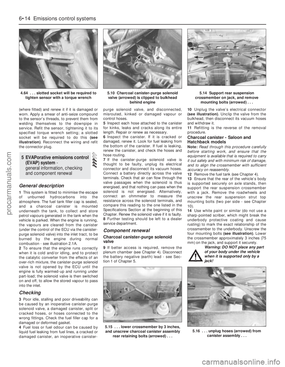
(where fitted) and renew it if it is damaged or
worn. Apply a smear of anti-seize compound
to the sensor’s threads, to prevent them from
welding themselves to the downpipe in
service. Refit the sensor, tightening it to its
specified torque wrench setting; a slotted
socket will be required to do this (see
illustration). Reconnect the wiring and refit
the connector plug.
General description
1This system is fitted to minimise the escape
of unburned hydrocarbons into the
atmosphere. The fuel tank filler cap is sealed,
and a charcoal canister is mounted
underneath the tank, to collect and store
petrol vapours generated in the tank when the
vehicle is parked. When the engine is running,
the vapours are cleared from the canister
(under the control of the ECU via the canister-
purge solenoid valve) into the inlet tract, to be
burned by the engine during normal
combustion - see illustration 2.1A.
2To ensure that the engine runs correctly
when it is cold and/or idling, and to protect
the catalytic converter from the effects of an
over-rich mixture, the canister-purge solenoid
valve is not opened by the ECU until the
engine is fully warmed-up and running under
part-load; the solenoid valve is then switched
on and off, to allow the stored vapour to pass
into the inlet.
Checking
3Poor idle, stalling and poor driveability can
be caused by an inoperative canister-purge
solenoid valve, a damaged canister, split or
cracked hoses, or hoses connected to the
wrong fittings. Check the fuel filler cap for a
damaged or deformed gasket.
4Fuel loss or fuel odour can be caused by
liquid fuel leaking from fuel lines, a cracked or
damaged canister, an inoperative canister-purge solenoid valve, and disconnected,
misrouted, kinked or damaged vapour or
control hoses.
5Inspect each hose attached to the canister
for kinks, leaks and cracks along its entire
length. Repair or renew as necessary.
6Inspect the canister. If it is cracked or
damaged, renew it. Look for fuel leaking from
the bottom of the canister. If fuel is leaking,
renew the canister, and check the hoses and
hose routing.
7If the canister-purge solenoid valve is
thought to be faulty, unplug its electrical
connector and disconnect its vacuum hoses.
Connect a battery directly across the valve
terminals. Check that air can flow through the
valve passages when the solenoid is thus
energised, and that nothing can pass when the
solenoid is not energised. Alternatively,
connect an ohmmeter to measure the
resistance across the solenoid terminals, and
compare this reading to the one listed in the
Specifications Section at the beginning of this
Chapter. Renew the solenoid valve if it is faulty.
8Further testing should be left to a dealer
service department.
Component renewal
Charcoal canister-purge solenoid
valve
9If better access is required, remove the
plenum chamber (see Chapter 4). Disconnect
the battery negative (earth) lead - see Sec-
tion 1 of Chapter 5.10Unplug the valve’s electrical connector
(see illustration). Unclip the valve from the
bulkhead, then disconnect its vacuum hoses
and withdraw it.
11Refitting is the reverse of the removal
procedure.
Charcoal canister - Saloon and
Hatchback models
Note:Read through this procedure carefully
before starting work, and ensure that the
equipment is available that is required to carry
it out safely and with minimum risk of damage,
and to align the crossmember with sufficient
accuracy on reassembly.
12Remove the fuel tank (see Chapter 4).
13Ensure that the rear of the vehicle’s body
is supported securely on axle stands, then
support the rear suspension crossmember
with a jack. Remove the roadwheels and
unscrew the rear suspension strut top
mounting bolts (two per side - see Chapter
10).
14Use white paint or similar (do not use a
sharp-pointed scriber, which might break the
underbody protective coating and cause
rusting) to mark the exact relationship of the
crossmember to the underbody. Unscrew the
four mounting bolts (see illustration). Lower
the crossmember approximately 3 inches (75
mm) on the jack, and support it securely.
Warning: DO NOT place any part
of your body under the vehicle
when it is supported only by a
jack!
5 EVAPorative emissions control
(EVAP) system -
general information, checking
and component renewal
6•14 Emissions control systems
4.64 . . . slotted socket will be required to
tighten sensor with a torque wrench5.10 Charcoal canister-purge solenoid
valve (arrowed) is clipped to bulkhead
behind engine5.14 Support rear suspension
crossmember on jack, and remove
mounting bolts (arrowed) . . .
5.15 . . . lower crossmember by 3 inches,
and unscrew charcoal canister assembly
rear retaining bolts (arrowed) . . .5.16 . . . unplug hoses (arrowed) from
canister assembly . . .
procarmanuals.com
Page 151 of 279
General information
1This system consists of the pulse-air
solenoid valve, the pulse-air valve itself,
contained in the filter housing, and the piping
- see illustration 2.1A. It injects filtered air
directly into the exhaust ports, using the
pressure variations in the exhaust gases to
draw air through from the filter housing; air will
flow into the exhaust only when its pressure is
below atmospheric. The pulse-air valve can
allow gases to flow only one way, so there is
no risk of hot exhaust gases flowing back into
the filter.
2The system’s primary function is raise
exhaust gas temperatures on start-up, thus
reducing the amount of time taken for the
oxygen sensor and catalytic converter to
reach operating temperature. Until this
happens, the system reduces emission of
unburned hydrocarbon particles (HC) and
carbon monoxide (CO) by ensuring that a
considerable proportion of these substances
remaining in the exhaust gases after
combustion are burned up, either in the
manifold itself or in the catalytic converter.
3To ensure that the system does not upset
the smooth running of the engine under
normal driving conditions, it is linked by the
pulse-air solenoid valve to the ECU, so that it
only functions during engine warm-up, when
the oxygen sensor is not influencing the
fuel/air mixture ratio.
Checking
4Poor idle, stalling, backfiring and poor
driveability can be caused by a fault in the
system.
5Inspect the vacuum pipe/hose connected
between the filter housing and the solenoid
valve for kinks, leaks and cracks along its
entire length. Repair or renew as necessary.
6Inspect the filter housing and piping. If
either is cracked or damaged, renew it.7If the pulse-air solenoid valve is thought to
be faulty, unplug its electrical connector and
disconnect its vacuum hoses. Connect a
battery directly across the valve terminals,
and check that air can flow through the valve
passages when the solenoid is thus
energised, and that nothing can pass when
the solenoid is not energised. Alternatively,
connect an ohmmeter to measure the
resistance across the valve terminals, and
compare this reading to the one listed in the
Specifications Section at the beginning of this
Chapter. Renew the solenoid valve if it is
faulty.
8Further testing should be left to a dealer
service department.
Component renewal
Pulse-air solenoid valve
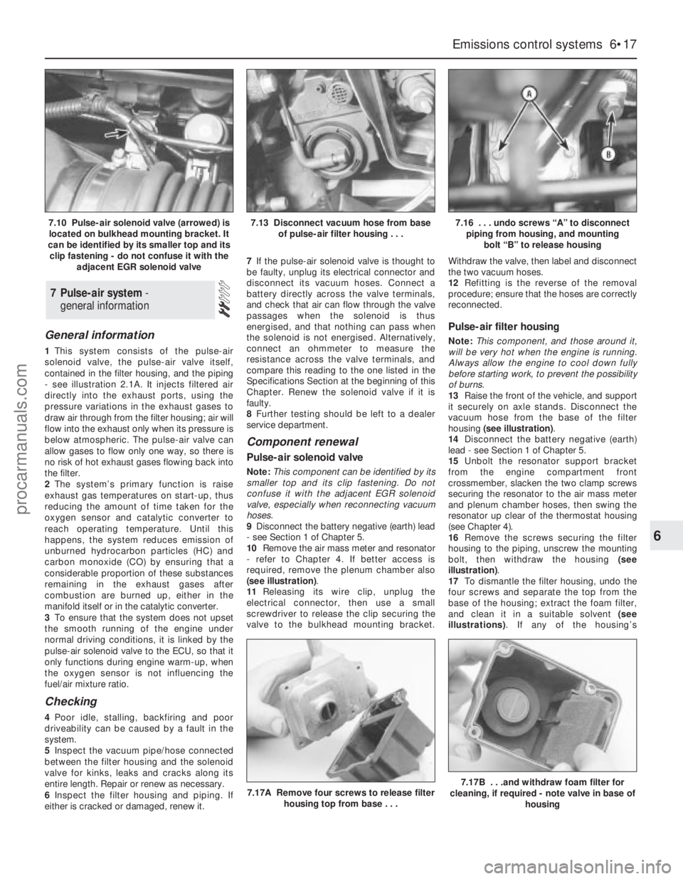
Note:This component can be identified by its
smaller top and its clip fastening. Do not
confuse it with the adjacent EGR solenoid
valve, especially when reconnecting vacuum
hoses.
9Disconnect the battery negative (earth) lead
- see Section 1 of Chapter 5.
10Remove the air mass meter and resonator
- refer to Chapter 4. If better access is
required, remove the plenum chamber also
(see illustration).
11Releasing its wire clip, unplug the
electrical connector, then use a small
screwdriver to release the clip securing the
valve to the bulkhead mounting bracket.Withdraw the valve, then label and disconnect
the two vacuum hoses.
12Refitting is the reverse of the removal
procedure; ensure that the hoses are correctly
reconnected.
Pulse-air filter housing
Note:This component, and those around it,
will be very hot when the engine is running.
Always allow the engine to cool down fully
before starting work, to prevent the possibility
of burns.
13Raise the front of the vehicle, and support
it securely on axle stands. Disconnect the
vacuum hose from the base of the filter
housing (see illustration).
14Disconnect the battery negative (earth)
lead - see Section 1 of Chapter 5.
15Unbolt the resonator support bracket
from the engine compartment front
crossmember, slacken the two clamp screws
securing the resonator to the air mass meter
and plenum chamber hoses, then swing the
resonator up clear of the thermostat housing
(see Chapter 4).
16Remove the screws securing the filter
housing to the piping, unscrew the mounting
bolt, then withdraw the housing (see
illustration).
17To dismantle the filter housing, undo the
four screws and separate the top from the
base of the housing; extract the foam filter,
and clean it in a suitable solvent (see
illustrations). If any of the housing’s
7 Pulse-air system -
general information
Emissions control systems 6•17
6
7.17A Remove four screws to release filter
housing top from base . . .7.17B . . .and withdraw foam filter for
cleaning, if required - note valve in base of
housing
7.10 Pulse-air solenoid valve (arrowed) is
located on bulkhead mounting bracket. It
can be identified by its smaller top and its
clip fastening - do not confuse it with the
adjacent EGR solenoid valve7.13 Disconnect vacuum hose from base
of pulse-air filter housing . . .7.16 . . . undo screws “A” to disconnect
piping from housing, and mounting
bolt “B” to release housing
procarmanuals.com
Page 153 of 279
2The function of these components is to
reduce the emission of unburned
hydrocarbons from the crankcase, and to
minimise the formation of oil sludge. By
ensuring that a depression is created in the
crankcase under most operating conditions,
particularly at idle, and by positively inducing
fresh air into the system, the oil vapours and
“blow-by” gases collected in the crankcase
are drawn from the crankcase, through the oil
separator, into the inlet tract, to be burned by
the engine during normal combustion.
Checking
3Checking procedures for the system
components are included in Chapter 1.
Component renewal
Cylinder head-to-air cleaner hose
4See Chapter 1.
Positive Crankcase Ventilation (PCV)
valve
5The valve is plugged into the oil separator.
Depending on the tools available, access to
the valve may be possible once the pulse-air
assembly has been removed (see Section 7).
If this is not feasible, proceed as outlined in
paragraph 6 below.
Oil separator
6Remove the exhaust manifold (see Chap-
ter 2, Part A). The Positive Crankcase
Ventilation (PCV) valve can now be unplugged
and flushed, or renewed, as required, as
described in Chapter 1.
7Unbolt the oil separator from the cylinder
block/crankcase, and withdraw it; remove and
discard the gasket.
8Flush out or renew the oil separator, as
required (see Chapter 1).
9On reassembly, fit a new gasket, and
tighten the fasteners to the torque wrench
settings given in the Specifications Section of
Chapter 2, Part B.
10The remainder of the refitting procedure is
the reverse of removal. Refill the cooling
system (see Chapter 1). Run the engine,
check for exhaust leaks, and check the
coolant level when it is fully warmed-up.
General information
1The exhaust gases of any petrol engine
(however efficient or well-tuned) consist
largely (approximately 99 %) of nitrogen (N
2),
carbon dioxide (CO
2), oxygen (O2), other inert
gases and water vapour (H
2O). The remaining
1 % is made up of the noxious materials
which are currently seen (CO
2apart) as the
major polluters of the environment: carbon
monoxide (CO), unburned hydrocarbons (HC),oxides of nitrogen (NO
x) and some solid
matter, including a small lead content.
2Left to themselves, most of these pollutants
are thought eventually to break down naturally
(CO and NO
x, for example, break down in the
upper atmosphere to release CO
2) having first
caused ground-level environmental problems.
The massive increase world-wide in the use of
motor vehicles, and the current popular
concern for the environment has caused the
introduction in most countries of legislation, in
varying degrees of severity, to combat the
problem.
3The device most commonly used to clean
up vehicle exhausts is the catalytic converter.
It is fitted into the vehicle’s exhaust system,
and uses precious metals (platinum and
palladium or rhodium) as catalysts to speed
up the reaction between the pollutants and
the oxygen in the vehicle’s exhaust gases, CO
and HC being oxidised to form H
2O and CO2and (in the three-way type of catalytic
converter) NO
xbeing reduced to N2. Note:
The catalytic converter is not a filter in the
physical sense; its function is to promote a
chemical reaction, but it is not itself affected
by that reaction.
4The converter consists of an element (or
“substrate”) of ceramic honeycomb, coated
with a combination of precious metals in such
a way as to produce a vast surface area over
which the exhaust gases must flow; the whole
being mounted in a stainless-steel box. A
simple “oxidation” (or “two-way”) catalytic
converter can deal with CO and HC only,
while a “reduction” (or “three-way”) catalytic
converter can deal with CO, HC and NO
x.
Three-way catalytic converters are further
sub-divided into “open-loop” (or
“uncontrolled”) converters which can remove
50 to 70 % of pollutants and “closed-loop”
(also known as “controlled” or “regulated”)
converters which can remove over 90 % of
pollutants.
5The catalytic converter fitted to the Mondeo
models covered in this manual is of the three-
way closed-loop type.
6The catalytic converter is a reliable and
simple device, which needs no maintenance
in itself, but there are some facts of which an
owner should be aware if the converter is to
function properly for its full service life.
(a) DO NOT use leaded petrol in a vehicle
equipped with a catalytic converter - the
lead will coat the precious metals,
reducing their converting efficiency, and
will eventually destroy the converter; it will
also affect the operation of the oxygen
sensor, requiring its renewal if lead-
fouled. Opinions vary as to how much
leaded fuel is necessary to affect the
converter’s performance, and whether it
can recover even if only unleaded petrol is
used afterwards; the best course of action
is, therefore, to assume the worst, and to
ensure that NO leaded petrol is used at
any time.
(b) Always keep the ignition and fuel systemswell-maintained in accordance with the
manufacturer’s schedule (Chapter 1) -
particularly, ensure that the air filter
element, the fuel filter and the spark plugs
are renewed at the correct intervals. If the
intake air/fuel mixture is allowed to
become too rich due to neglect, the
unburned surplus will enter and burn in
the catalytic converter, overheating the
element and eventually destroying the
converter.
(c) If the engine develops a misfire, do not
drive the vehicle at all (or at least as little
as possible) until the fault is cured - the
misfire will allow unburned fuel to enter
the converter, which will result in its
overheating, as noted above. For the
same reason, do not persist if the engine
refuses to start - either trace the problem
and cure it yourself, or have the vehicle
checked immediately by a qualified
mechanic.
(d) Avoid allowing the vehicle to run out of
petrol.
(e) DO NOT push- or tow-start the vehicle
unless no other alternative exists,
especially if the engine and exhaust are at
normal operating temperature. Starting
the engine in this way may soak the
catalytic converter in unburned fuel,
causing it to overheat when the engine
does start - see (b) above.
(f) DO NOT switch off the ignition at high
engine speeds, in particular, do not “blip”
the throttle immediately before switching
off. If the ignition is switched off at
anything above idle speed, unburned fuel
will enter the (very hot) catalytic converter,
with the possible risk of its igniting on the
element and damaging the converter.
(g) Avoid repeated successive cold starts
followed by short journeys. If the
converter is never allowed to reach its
proper working temperature, it will gather
unburned fuel, allowing some to pass into
the atmosphere and the rest to soak in
the element, causing it to overheat when
a long journey is made - see (b) above.
(h) DO NOT use fuel or engine oil additives -
these may contain substances harmful to
the catalytic converter. Similarly, DO NOT
use silicone-based sealants on any part of
the engine or fuel system, and do not use
exhaust sealants on any part of the
exhaust system upstream of the catalytic
converter. Even if the sealant itself does
not contain additives harmful to the
converter, pieces of it may break off and
foul the element, causing local
overheating.
(i) DO NOT continue to use the vehicle if the
engine burns oil to the extent of leaving a
visible trail of blue smoke. Unburned
carbon deposits will clog the converter
passages and reduce its efficiency; in
severe cases, the element will overheat.
(j) Remember that the catalytic converter
operates at very high temperatures -
9 Catalytic converter -
general information, checking
and component renewal
Emissions control systems 6•19
6
procarmanuals.com
Page 154 of 279
hence the heat shields on the vehicle
underbody - and the casing will become
hot enough to ignite combustible
materials which brush against it. DO NOT,
therefore, park the vehicle in dry
undergrowth, over long grass or piles of
dead leaves.
(k) Remember that the catalytic converter is
FRAGILE. Do not strike it with tools
during servicing work, and take great care
when working on the exhaust system (see
Chapter 4). Ensure that the converter is
well clear of any jacks or other lifting gear
used to raise the vehicle. Do not drive the
vehicle over rough ground, road humps,
etc, in such a way as to “ground” the
exhaust system.
(l) In some cases, particularly when the
vehicle is new and/or is used for
stop/start driving, a sulphurous smell (like
that of rotten eggs) may be noticed fromthe exhaust. This is common to many
catalytic converter-equipped vehicles,
and seems to be due to the small amount
of sulphur found in some petrols reacting
with hydrogen in the exhaust, to produce
hydrogen sulphide (H
2S) gas; while this
gas is toxic, it is not produced in sufficient
amounts to be a problem. Once the
vehicle has covered a few thousand miles,
the problem should disappear - in the
meanwhile, a change of driving style, or of
the brand of petrol used, may effect a
solution.
(m) The catalytic converter on a well-
maintained and well-driven vehicle should
last for between 50 000 and 100 000
miles. From this point on, careful checks
should be made at regular intervals to
ensure that the converter is still operating
efficiently. If the converter is no longer
effective, it must be renewed.
Checking
7Checking the operation of a catalytic
converter requires expensive and
sophisticated diagnostic equipment, starting
with a high-quality exhaust gas analyser. If the
level of CO in the exhaust gases is too high, a
full check of the engine management system
must be carried out (see Section 3 of this
Chapter) to eliminate all other possibilities
before the converter is suspected of being
faulty.
8The vehicle should be taken to a Ford
dealer for this work to be carried out using the
correct diagnostic equipment; do not waste
time trying to test the system without such
facilities.
Component renewal
9The catalytic converter is part of the
exhaust system front downpipe - see Chap-
ter 4 for details of removal and refitting.
6•20 Emissions control systems
procarmanuals.com
Page 273 of 279
REF•14Glossary of Technical Terms
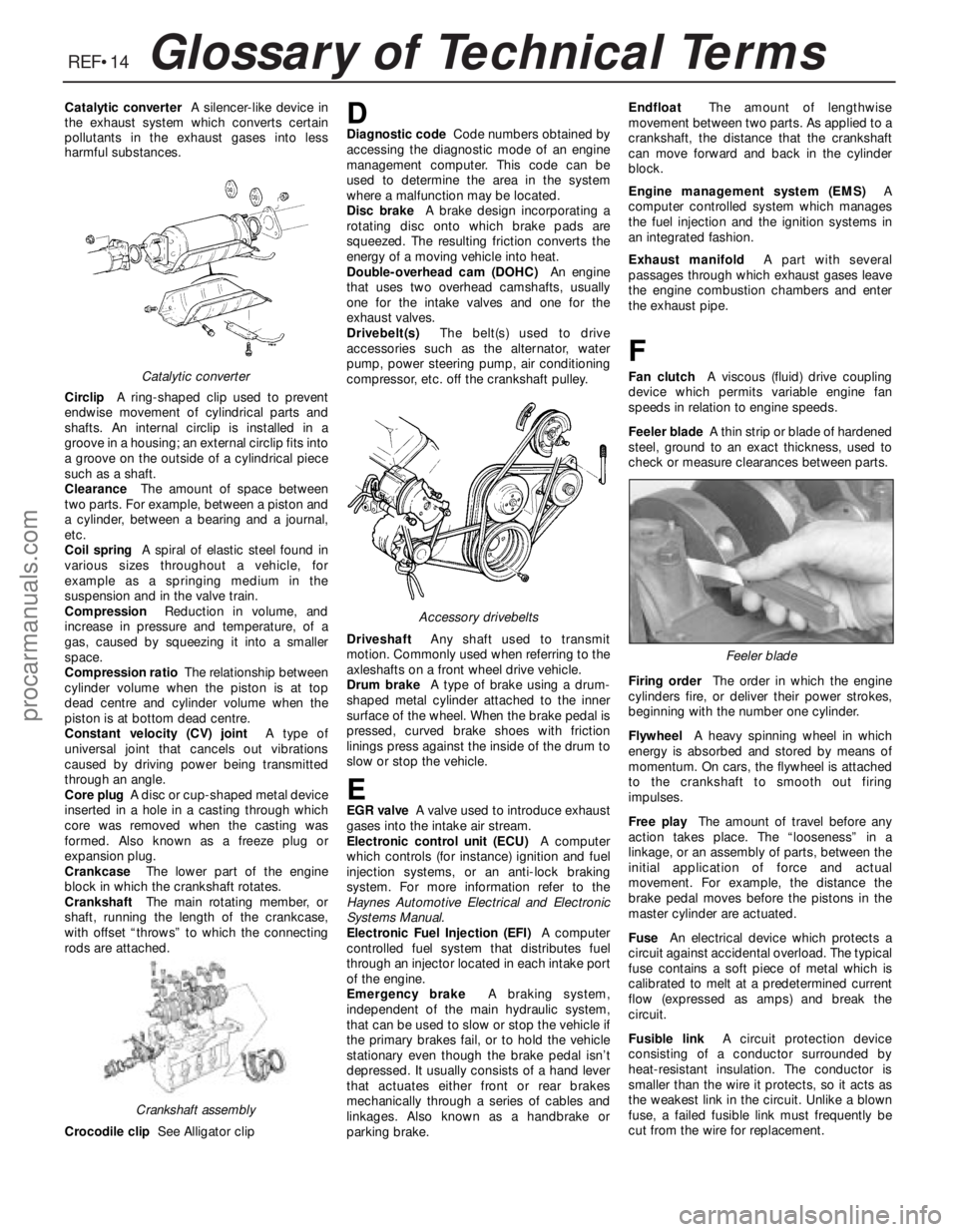
Catalytic converterA silencer-like device in
the exhaust system which converts certain
pollutants in the exhaust gases into less
harmful substances.
CirclipA ring-shaped clip used to prevent
endwise movement of cylindrical parts and
shafts. An internal circlip is installed in a
groove in a housing; an external circlip fits into
a groove on the outside of a cylindrical piece
such as a shaft.
ClearanceThe amount of space between
two parts. For example, between a piston and
a cylinder, between a bearing and a journal,
etc.
Coil springA spiral of elastic steel found in
various sizes throughout a vehicle, for
example as a springing medium in the
suspension and in the valve train.
CompressionReduction in volume, and
increase in pressure and temperature, of a
gas, caused by squeezing it into a smaller
space.
Compression ratioThe relationship between
cylinder volume when the piston is at top
dead centre and cylinder volume when the
piston is at bottom dead centre.
Constant velocity (CV) jointA type of
universal joint that cancels out vibrations
caused by driving power being transmitted
through an angle.
Core plugA disc or cup-shaped metal device
inserted in a hole in a casting through which
core was removed when the casting was
formed. Also known as a freeze plug or
expansion plug.
CrankcaseThe lower part of the engine
block in which the crankshaft rotates.
CrankshaftThe main rotating member, or
shaft, running the length of the crankcase,
with offset “throws” to which the connecting
rods are attached.
Crocodile clipSee Alligator clipDDiagnostic codeCode numbers obtained by
accessing the diagnostic mode of an engine
management computer. This code can be
used to determine the area in the system
where a malfunction may be located.
Disc brakeA brake design incorporating a
rotating disc onto which brake pads are
squeezed. The resulting friction converts the
energy of a moving vehicle into heat.
Double-overhead cam (DOHC)An engine
that uses two overhead camshafts, usually
one for the intake valves and one for the
exhaust valves.
Drivebelt(s)The belt(s) used to drive
accessories such as the alternator, water
pump, power steering pump, air conditioning
compressor, etc. off the crankshaft pulley.
DriveshaftAny shaft used to transmit
motion. Commonly used when referring to the
axleshafts on a front wheel drive vehicle.
Drum brakeA type of brake using a drum-
shaped metal cylinder attached to the inner
surface of the wheel. When the brake pedal is
pressed, curved brake shoes with friction
linings press against the inside of the drum to
slow or stop the vehicle.
EEGR valveA valve used to introduce exhaust
gases into the intake air stream.
Electronic control unit (ECU)A computer
which controls (for instance) ignition and fuel
injection systems, or an anti-lock braking
system. For more information refer to the
Haynes Automotive Electrical and Electronic
Systems Manual.
Electronic Fuel Injection (EFI)A computer
controlled fuel system that distributes fuel
through an injector located in each intake port
of the engine.
Emergency brakeA braking system,
independent of the main hydraulic system,
that can be used to slow or stop the vehicle if
the primary brakes fail, or to hold the vehicle
stationary even though the brake pedal isn’t
depressed. It usually consists of a hand lever
that actuates either front or rear brakes
mechanically through a series of cables and
linkages. Also known as a handbrake or
parking brake.EndfloatThe amount of lengthwise
movement between two parts. As applied to a
crankshaft, the distance that the crankshaft
can move forward and back in the cylinder
block.
Engine management system (EMS)A
computer controlled system which manages
the fuel injection and the ignition systems in
an integrated fashion.
Exhaust manifoldA part with several
passages through which exhaust gases leave
the engine combustion chambers and enter
the exhaust pipe.
F
Fan clutchA viscous (fluid) drive coupling
device which permits variable engine fan
speeds in relation to engine speeds.
Feeler bladeA thin strip or blade of hardened
steel, ground to an exact thickness, used to
check or measure clearances between parts.
Firing orderThe order in which the engine
cylinders fire, or deliver their power strokes,
beginning with the number one cylinder.
Flywheel A heavy spinning wheel in which
energy is absorbed and stored by means of
momentum. On cars, the flywheel is attached
to the crankshaft to smooth out firing
impulses.
Free playThe amount of travel before any
action takes place. The “looseness” in a
linkage, or an assembly of parts, between the
initial application of force and actual
movement. For example, the distance the
brake pedal moves before the pistons in the
master cylinder are actuated.
FuseAn electrical device which protects a
circuit against accidental overload. The typical
fuse contains a soft piece of metal which is
calibrated to melt at a predetermined current
flow (expressed as amps) and break the
circuit.
Fusible linkA circuit protection device
consisting of a conductor surrounded by
heat-resistant insulation. The conductor is
smaller than the wire it protects, so it acts as
the weakest link in the circuit. Unlike a blown
fuse, a failed fusible link must frequently be
cut from the wire for replacement.Catalytic converter
Crankshaft assembly
Accessory drivebelts
Feeler blade
procarmanuals.com