window FORD MONDEO 1993 Service Owner's Manual
[x] Cancel search | Manufacturer: FORD, Model Year: 1993, Model line: MONDEO, Model: FORD MONDEO 1993Pages: 279, PDF Size: 12.71 MB
Page 208 of 279
Main light, auxiliary foglight and rear
foglight combination switch
Note:From July 1994 a rvised main light
switch was introduced; this was fitted as
standard in production. If the revised switch is
to be fitted to a pre-July 1994 model, an
adapter lead will also be required to prevent
electrical damage ocurring. Refer to your Ford
dealer for further information
9Disconnect the battery negative (earth) lead
(refer to Chapter 5, Section 1).
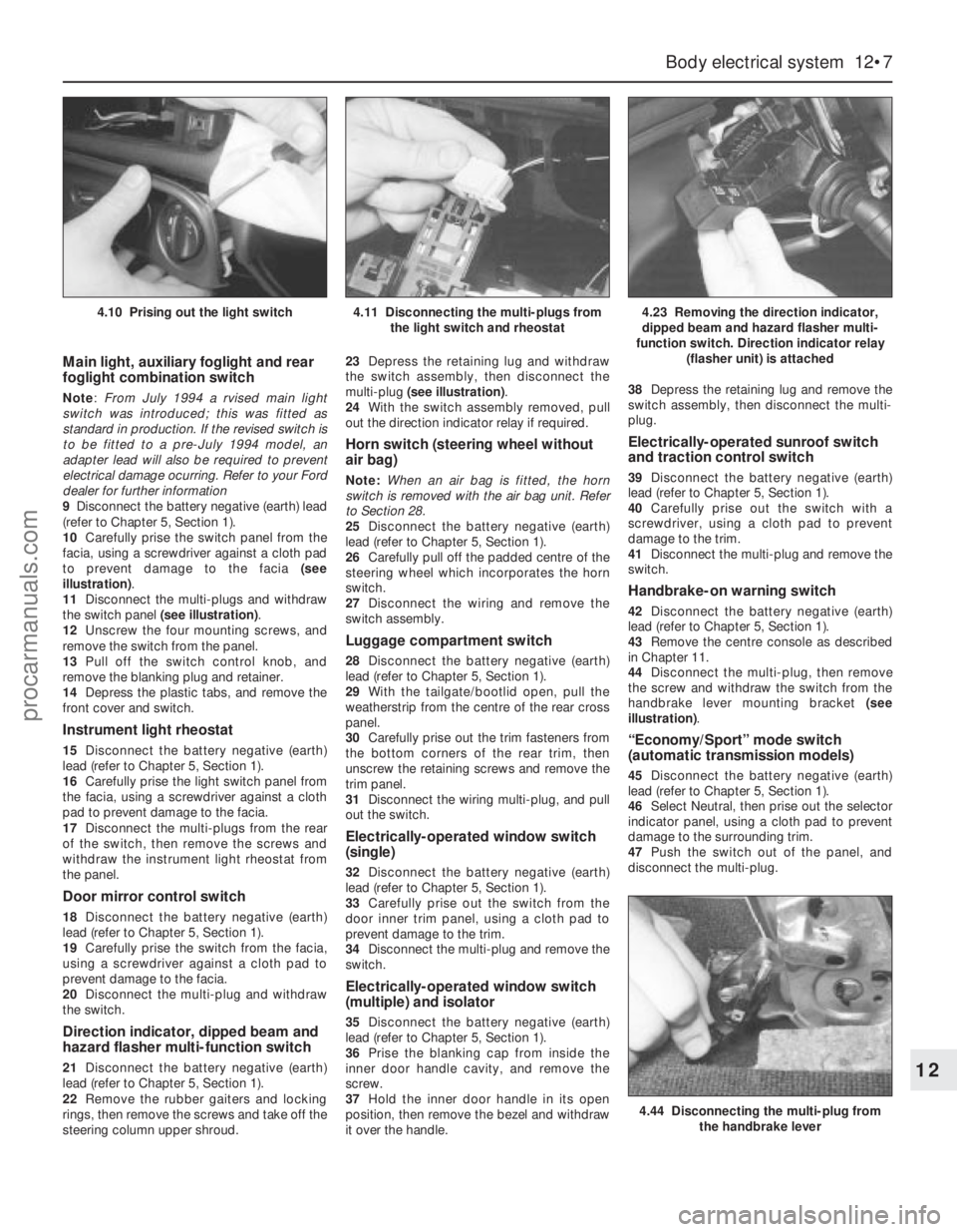
10Carefully prise the switch panel from the
facia, using a screwdriver against a cloth pad
to prevent damage to the facia (see
illustration).
11Disconnect the multi-plugs and withdraw
the switch panel (see illustration).
12Unscrew the four mounting screws, and
remove the switch from the panel.
13Pull off the switch control knob, and
remove the blanking plug and retainer.
14Depress the plastic tabs, and remove the
front cover and switch.
Instrument light rheostat
15Disconnect the battery negative (earth)
lead (refer to Chapter 5, Section 1).
16Carefully prise the light switch panel from
the facia, using a screwdriver against a cloth
pad to prevent damage to the facia.
17Disconnect the multi-plugs from the rear
of the switch, then remove the screws and
withdraw the instrument light rheostat from
the panel.
Door mirror control switch
18Disconnect the battery negative (earth)
lead (refer to Chapter 5, Section 1).
19Carefully prise the switch from the facia,
using a screwdriver against a cloth pad to
prevent damage to the facia.
20Disconnect the multi-plug and withdraw
the switch.
Direction indicator, dipped beam and
hazard flasher multi-function switch
21Disconnect the battery negative (earth)
lead (refer to Chapter 5, Section 1).
22Remove the rubber gaiters and locking
rings, then remove the screws and take off the
steering column upper shroud.23Depress the retaining lug and withdraw
the switch assembly, then disconnect the
multi-plug (see illustration).
24With the switch assembly removed, pull
out the direction indicator relay if required.
Horn switch (steering wheel without
air bag)
Note:When an air bag is fitted, the horn
switch is removed with the air bag unit. Refer
to Section 28.
25Disconnect the battery negative (earth)
lead (refer to Chapter 5, Section 1).
26Carefully pull off the padded centre of the
steering wheel which incorporates the horn
switch.
27Disconnect the wiring and remove the
switch assembly.
Luggage compartment switch
28Disconnect the battery negative (earth)
lead (refer to Chapter 5, Section 1).
29With the tailgate/bootlid open, pull the
weatherstrip from the centre of the rear cross
panel.
30Carefully prise out the trim fasteners from
the bottom corners of the rear trim, then
unscrew the retaining screws and remove the
trim panel.
31Disconnect the wiring multi-plug, and pull
out the switch.
Electrically-operated window switch
(single)
32Disconnect the battery negative (earth)
lead (refer to Chapter 5, Section 1).
33Carefully prise out the switch from the
door inner trim panel, using a cloth pad to
prevent damage to the trim.
34Disconnect the multi-plug and remove the
switch.
Electrically-operated window switch
(multiple) and isolator
35Disconnect the battery negative (earth)
lead (refer to Chapter 5, Section 1).
36Prise the blanking cap from inside the
inner door handle cavity, and remove the
screw.
37Hold the inner door handle in its open
position, then remove the bezel and withdraw
it over the handle.38Depress the retaining lug and remove the
switch assembly, then disconnect the multi-
plug.
Electrically-operated sunroof switch
and traction control switch
39Disconnect the battery negative (earth)
lead (refer to Chapter 5, Section 1).
40Carefully prise out the switch with a
screwdriver, using a cloth pad to prevent
damage to the trim.
41Disconnect the multi-plug and remove the
switch.
Handbrake-on warning switch
42Disconnect the battery negative (earth)
lead (refer to Chapter 5, Section 1).
43Remove the centre console as described
in Chapter 11.
44Disconnect the multi-plug, then remove
the screw and withdraw the switch from the
handbrake lever mounting bracket (see
illustration).
“Economy/Sport” mode switch
(automatic transmission models)
45Disconnect the battery negative (earth)
lead (refer to Chapter 5, Section 1).
46Select Neutral, then prise out the selector
indicator panel, using a cloth pad to prevent
damage to the surrounding trim.
47Push the switch out of the panel, and
disconnect the multi-plug.
Body electrical system 12•7
12
4.44 Disconnecting the multi-plug from
the handbrake lever
4.10 Prising out the light switch4.11 Disconnecting the multi-plugs from
the light switch and rheostat4.23 Removing the direction indicator,
dipped beam and hazard flasher multi-
function switch. Direction indicator relay
(flasher unit) is attached
procarmanuals.com
Page 209 of 279

Heated windscreen switch and heated
rear window switch
48Disconnect the battery negative (earth)
lead (refer to Chapter 5, Section 1).
49Carefully prise out the switch, using a
cloth pad to prevent damage to the trim (see
illustration).
50Disconnect the multi-plug and remove the
switch (see illustration).
Electrically-operated seat switch and
heated seat switch
51Disconnect the battery negative (earth)
lead (refer to Chapter 5, Section 1).
52Carefully prise out the switch, using a
cloth pad to prevent damage to the trim.
53Disconnect the multi-plug and remove the
switch.
Adaptive damping switch
54Disconnect the battery negative (earth)
lead (refer to Chapter 5, Section 1).
55Carefully prise out the switch, using a
cloth pad to prevent damage to the trim.
56Disconnect the multi-plug and remove the
switch.
Courtesy light door switch
57Open the door, then unscrew the cross-
head screw and carefully pull the switch from
the pillar (see illustrations). Take care not to
force the wire from the switch terminal,
otherwise it will be difficult to retrieve it from
the pillar.
58Disconnect the wire, and tie it in a loose
knot to prevent it dropping back into the
pillar.
Refitting
59Refitting of all switches is a reversal of the
removal procedure.
Note:Ensure that all exterior lights are
switched off before disconnecting the wiring
connectors from any exterior light bulbs. Do
not touch the glass of halogen-type bulbs
(headlights, front foglights) with the fingers; if
the glass is accidentally touched, clean it with
methylated spirit.
Headlight (dipped beam)
1Working under the bonnet, depress the
plastic clips and remove the cover from the
rear of the headlight unit (see illustration).
2Release the spring clip and withdraw the
bulb, then disconnect the wiring lead (see
illustrations).
3Fit the new bulb using a reversal of the
removal procedure. Have the headlight beam
alignment checked as described later in this
Chapter.
Headlight (main beam)
4Working under the bonnet, depress the
plastic clips and remove the cover from the
rear of the headlight unit.
5Turn the bulbholder anti-clockwise, and
remove it from the rear of the headlight unit
(see illustration).
5 Bulbs (exterior lights) -
renewal
12•8 Body electrical system
4.49 Prising out the heated rear window
switch4.50 Disconnecting the multi-plug from
the heated rear window switch4.57A Unscrew the cross-head screw . . .
5.2A Release the spring clip . . .5.2B . . . and withdraw the headlight bulb
4.57B . . . and pull out the courtesy light
switch5.1 Removing the cover from the rear of
the headlight
5.5 Removing the headlight (main beam)
bulbholder
procarmanuals.com
Page 215 of 279
2Where fitted, remove the clock as
described in Section 13.
3Where fitted, remove the trip computer
module as described in Section 18.
4Remove the heated rear window switch as
described in Section 4.
5Where fitted, remove the heated
windscreen switch.
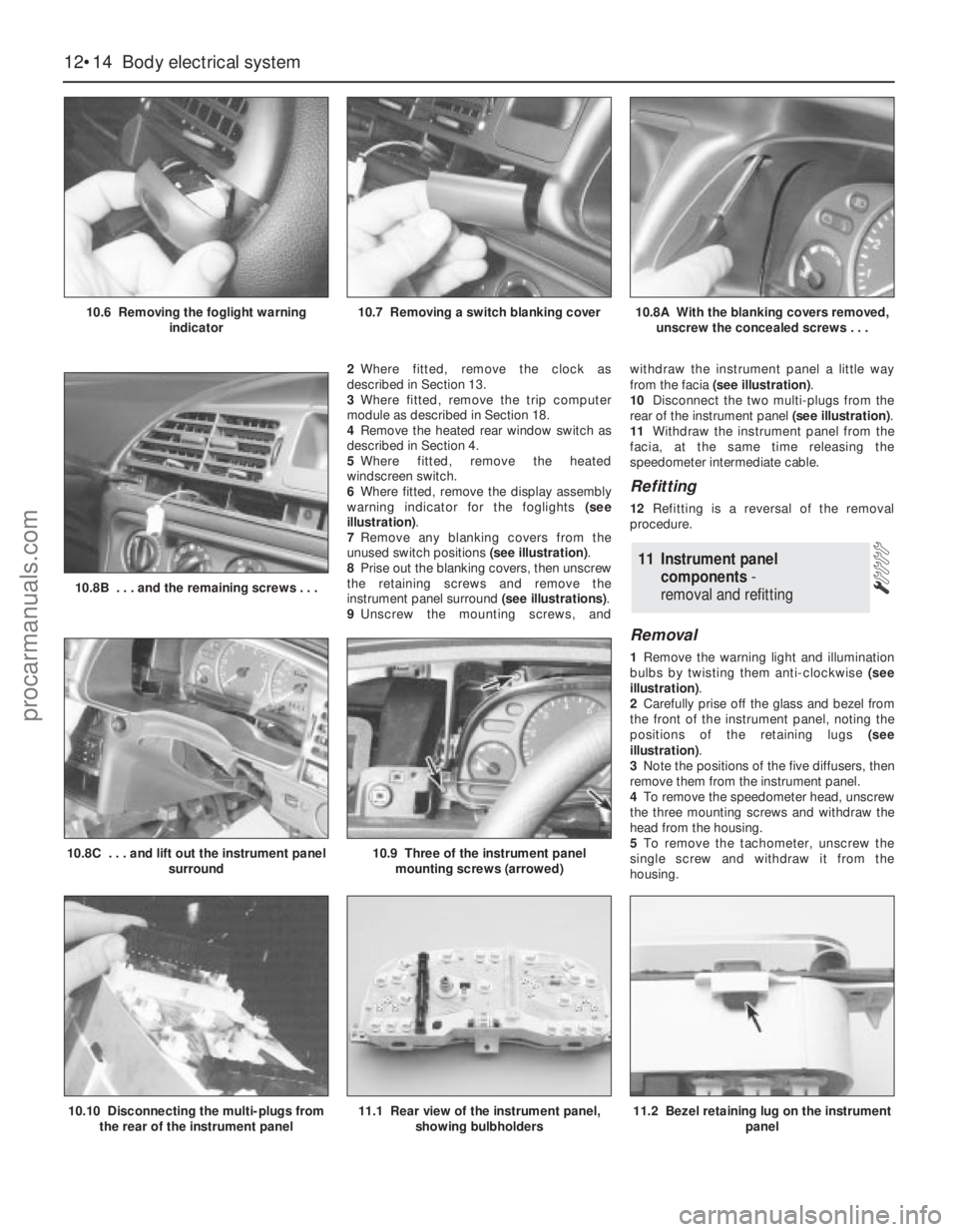
6Where fitted, remove the display assembly
warning indicator for the foglights (see
illustration).
7Remove any blanking covers from the
unused switch positions (see illustration).
8Prise out the blanking covers, then unscrew
the retaining screws and remove the
instrument panel surround (see illustrations).
9Unscrew the mounting screws, andwithdraw the instrument panel a little way
from the facia (see illustration).
10Disconnect the two multi-plugs from the
rear of the instrument panel (see illustration).
11Withdraw the instrument panel from the
facia, at the same time releasing the
speedometer intermediate cable.
Refitting
12Refitting is a reversal of the removal
procedure.
Removal
1Remove the warning light and illumination
bulbs by twisting them anti-clockwise (see
illustration).
2Carefully prise off the glass and bezel from
the front of the instrument panel, noting the
positions of the retaining lugs (see
illustration).
3Note the positions of the five diffusers, then
remove them from the instrument panel.
4To remove the speedometer head, unscrew
the three mounting screws and withdraw the
head from the housing.
5To remove the tachometer, unscrew the
single screw and withdraw it from the
housing.
11 Instrument panel
components-
removal and refitting
12•14 Body electrical system
10.6 Removing the foglight warning
indicator10.7 Removing a switch blanking cover10.8A With the blanking covers removed,
unscrew the concealed screws . . .
10.10 Disconnecting the multi-plugs from
the rear of the instrument panel11.1 Rear view of the instrument panel,
showing bulbholders11.2 Bezel retaining lug on the instrument
panel
10.8C . . . and lift out the instrument panel
surround10.9 Three of the instrument panel
mounting screws (arrowed)
10.8B . . . and the remaining screws . . .
procarmanuals.com
Page 222 of 279
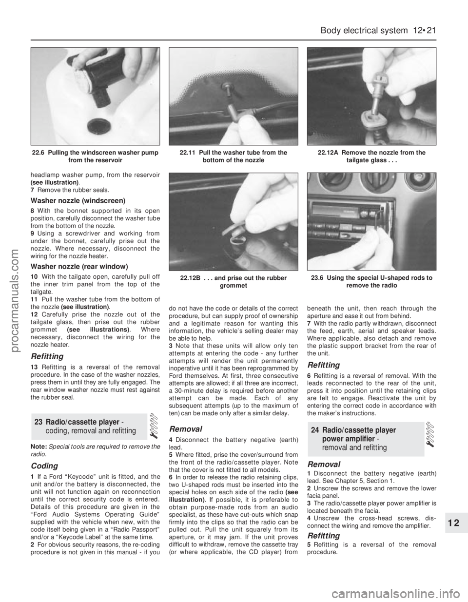
headlamp washer pump, from the reservoir
(see illustration).
7Remove the rubber seals.
Washer nozzle (windscreen)
8With the bonnet supported in its open
position, carefully disconnect the washer tube
from the bottom of the nozzle.
9Using a screwdriver and working from
under the bonnet, carefully prise out the
nozzle. Where necessary, disconnect the
wiring for the nozzle heater.
Washer nozzle (rear window)
10With the tailgate open, carefully pull off
the inner trim panel from the top of the
tailgate.
11Pull the washer tube from the bottom of
the nozzle (see illustration).
12Carefully prise the nozzle out of the
tailgate glass, then prise out the rubber
grommet (see illustrations). Where
necessary, disconnect the wiring for the
nozzle heater.
Refitting
13Refitting is a reversal of the removal
procedure. In the case of the washer nozzles,
press them in until they are fully engaged. The
rear window washer nozzle must rest against
the rubber seal.
Note:Special tools are required to remove the
radio.
Coding
1If a Ford “Keycode” unit is fitted, and the
unit and/or the battery is disconnected, the
unit will not function again on reconnection
until the correct security code is entered.
Details of this procedure are given in the
“Ford Audio Systems Operating Guide”
supplied with the vehicle when new, with the
code itself being given in a “Radio Passport”
and/or a “Keycode Label” at the same time.
2For obvious security reasons, the re-coding
procedure is not given in this manual - if youdo not have the code or details of the correct
procedure, but can supply proof of ownership
and a legitimate reason for wanting this
information, the vehicle’s selling dealer may
be able to help.
3Note that these units will allow only ten
attempts at entering the code - any further
attempts will render the unit permanently
inoperative until it has been reprogrammed by
Ford themselves. At first, three consecutive
attempts are allowed; if all three are incorrect,
a 30-minute delay is required before another
attempt can be made. Each of any
subsequent attempts (up to the maximum of
ten) can be made only after a similar delay.
Removal
4Disconnect the battery negative (earth)
lead.
5Where fitted, prise the cover/surround from
the front of the radio/cassette player. Note
that the cover is not fitted to all models.
6In order to release the radio retaining clips,
two U-shaped rods must be inserted into the
special holes on each side of the radio (see
illustration). If possible, it is preferable to
obtain purpose-made rods from an audio
specialist, as these have cut-outs which snap
firmly into the clips so that the radio can be
pulled out. Pull the unit squarely from its
aperture, or it may jam. If the unit proves
difficult to withdraw, remove the cassette tray
(or where applicable, the CD player) frombeneath the unit, then reach through the
aperture and ease it out from behind.
7With the radio partly withdrawn, disconnect
the feed, earth, aerial and speaker leads.
Where applicable, also detach and remove
the plastic support bracket from the rear of
the unit.
Refitting
6Refitting is a reversal of removal. With the
leads reconnected to the rear of the unit,
press it into position until the retaining clips
are felt to engage. Reactivate the unit by
entering the correct code in accordance with
the maker’s instructions.
Removal
1Disconnect the battery negative (earth)
lead. See Chapter 5, Section 1.
2Unscrew the screws and remove the lower
facia panel.
3The radio/cassette player power amplifier is
located beneath the facia.
4Unscrew the cross-head screws, dis-
connect the wiring and remove the amplifier.
Refitting
5Refitting is a reversal of the removal
procedure.
24 Radio/cassette player
power amplifier -
removal and refitting
23 Radio/cassette player -
coding, removal and refitting
Body electrical system 12•21
12
22.12B . . . and prise out the rubber
grommet23.6 Using the special U-shaped rods to
remove the radio
22.6 Pulling the windscreen washer pump
from the reservoir22.11 Pull the washer tube from the
bottom of the nozzle22.12A Remove the nozzle from the
tailgate glass . . .
procarmanuals.com
Page 247 of 279

12•46 Wiring diagrams
Diagram 22: Electric mirrors and (front) electric window
procarmanuals.com
Page 248 of 279

Wiring diagrams 12•47
12
Diagram 23: Electric sunroof and (front and rear) electric windows
procarmanuals.com
Page 265 of 279
REF•6Fault Finding
Engine 1
m mEngine backfires
m mEngine difficult to start when cold
m mEngine difficult to start when hot
m mEngine fails to rotate when attempting to start
m mEngine hesitates on acceleration
m mEngine idles erratically
m mEngine lacks power
m mEngine misfires at idle speed
m mEngine misfires throughout the driving speed range
m mEngine noises
m mEngine rotates but will not start
m mEngine runs-on after switching off
m mEngine stalls
m mEngine starts but stops immediately
m mOil pressure warning light illuminated with engine running
m mStarter motor noisy or excessively-rough in engagement
Cooling system 2
m
mCorrosion
m mExternal coolant leakage
m mInternal coolant leakage
m mOvercooling
m mOverheating
Fuel and exhaust systems 3
m
mExcessive fuel consumption
m mExcessive noise or fumes from exhaust system
m mFuel leakage and/or fuel odour
Clutch 4
m
mClutch fails to disengage (unable to select gears)
m mClutch slips (engine speed increases with no increase
in vehicle speed)
m mJudder as clutch is engaged
m mNoise when depressing or releasing clutch pedal
m mPedal travels to floor - no pressure or very little resistance
Manual transmission 5
m
mJumps out of gear
m mLubricant leaks
m mNoisy in neutral with engine running
m mNoisy in one particular gear
m mVibration
Automatic transmission 6
m
mEngine will not start in any gear, or starts in gears
other than Park or Neutral
m mFluid leakage
m mGeneral gear selection problems
m mTransmission fluid brown, or has burned smell
m mTransmission slips, shifts roughly, is noisy, or
has no drive in forward or reverse gears
m mTransmission will not downshift (kickdown) with
accelerator fully depressed
Driveshafts 7
m mClicking or knocking noise on turns (at slow speed on full-lock)
m mVibration when accelerating or decelerating
Braking system 8
m
mBrake pedal feels spongy when depressed
m mBrakes binding
m mExcessive brake pedal effort required to stop vehicle
m mExcessive brake pedal travel
m mJudder felt through brake pedal or steering wheel when braking
m mNoise (grinding or high-pitched squeal) when brakes applied
m mRear wheels locking under normal braking
m mVehicle pulls to one side under braking
Suspension and steering systems 9
m
mExcessive pitching and/or rolling around corners, or during
braking
m mExcessive play in steering
m mExcessively-stiff steering
m mLack of power assistance
m mTyre wear excessive
m mVehicle pulls to one side
m mWandering or general instability
m mWheel wobble and vibration
Electrical system 10
m
mBattery will not hold a charge for more than a few days
m mCentral locking system inoperative, or unsatisfactory in operation
m mElectric windows inoperative, or unsatisfactory in operation
m mHorn inoperative, or unsatisfactory in operation
m mIgnition warning light fails to come on
m mIgnition warning light remains illuminated with engine running
m mInstrument readings inaccurate or erratic
m mLights inoperative
m mWindscreen/tailgate washers inoperative, or unsatisfactory in
operation
m mWindscreen/tailgate wipers inoperative, or unsatisfactory in
operation
procarmanuals.com
Page 271 of 279
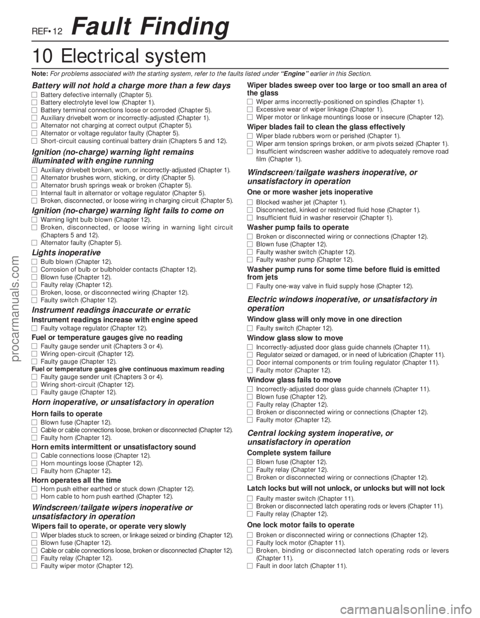
REF•12
Battery will not hold a charge more than a few days
m mBattery defective internally (Chapter 5).
m mBattery electrolyte level low (Chapter 1).
m mBattery terminal connections loose or corroded (Chapter 5).
m mAuxiliary drivebelt worn or incorrectly-adjusted (Chapter 1).
m mAlternator not charging at correct output (Chapter 5).
m mAlternator or voltage regulator faulty (Chapter 5).
m mShort-circuit causing continual battery drain (Chapters 5 and 12).
Ignition (no-charge) warning light remains
illuminated with engine running
m mAuxiliary drivebelt broken, worn, or incorrectly-adjusted (Chapter 1).
m mAlternator brushes worn, sticking, or dirty (Chapter 5).
m mAlternator brush springs weak or broken (Chapter 5).
m mInternal fault in alternator or voltage regulator (Chapter 5).
m mBroken, disconnected, or loose wiring in charging circuit (Chapter 5).
Ignition (no-charge) warning light fails to come on
m
mWarning light bulb blown (Chapter 12).
m mBroken, disconnected, or loose wiring in warning light circuit
(Chapters 5 and 12).
m mAlternator faulty (Chapter 5).
Lights inoperative
m
mBulb blown (Chapter 12).
m mCorrosion of bulb or bulbholder contacts (Chapter 12).
m mBlown fuse (Chapter 12).
m mFaulty relay (Chapter 12).
m mBroken, loose, or disconnected wiring (Chapter 12).
m mFaulty switch (Chapter 12).
Instrument readings inaccurate or erratic
Instrument readings increase with engine speed
m
mFaulty voltage regulator (Chapter 12).
Fuel or temperature gauges give no reading
m
mFaulty gauge sender unit (Chapters 3 or 4).
m mWiring open-circuit (Chapter 12).
m mFaulty gauge (Chapter 12).
Fuel or temperature gauges give continuous maximum reading
m mFaulty gauge sender unit (Chapters 3 or 4).
m mWiring short-circuit (Chapter 12).
m mFaulty gauge (Chapter 12).
Horn inoperative, or unsatisfactory in operation
Horn fails to operate
m
mBlown fuse (Chapter 12).
m mCable or cable connections loose, broken or disconnected (Chapter 12).
m mFaulty horn (Chapter 12).
Horn emits intermittent or unsatisfactory sound
m
mCable connections loose (Chapter 12).
m mHorn mountings loose (Chapter 12).
m mFaulty horn (Chapter 12).
Horn operates all the time
m
mHorn push either earthed or stuck down (Chapter 12).
m mHorn cable to horn push earthed (Chapter 12).
Windscreen/tailgate wipers inoperative or
unsatisfactory in operation
Wipers fail to operate, or operate very slowly
m mWiper blades stuck to screen, or linkage seized or binding (Chapter 12).
m mBlown fuse (Chapter 12).
m mCable or cable connections loose, broken or disconnected (Chapter 12).
m mFaulty relay (Chapter 12).
m mFaulty wiper motor (Chapter 12).
Wiper blades sweep over too large or too small an area of
the glass
m mWiper arms incorrectly-positioned on spindles (Chapter 1).
m mExcessive wear of wiper linkage (Chapter 1).
m mWiper motor or linkage mountings loose or insecure (Chapter 12).
Wiper blades fail to clean the glass effectively
m
mWiper blade rubbers worn or perished (Chapter 1).
m mWiper arm tension springs broken, or arm pivots seized (Chapter 1).
m mInsufficient windscreen washer additive to adequately remove road
film (Chapter 1).
Windscreen/tailgate washers inoperative, or
unsatisfactory in operation
One or more washer jets inoperative
m mBlocked washer jet (Chapter 1).
m mDisconnected, kinked or restricted fluid hose (Chapter 1).
m mInsufficient fluid in washer reservoir (Chapter 1).
Washer pump fails to operate
m
mBroken or disconnected wiring or connections (Chapter 12).
m mBlown fuse (Chapter 12).
m mFaulty washer switch (Chapter 12).
m mFaulty washer pump (Chapter 12).
Washer pump runs for some time before fluid is emitted
from jets
m mFaulty one-way valve in fluid supply hose (Chapter 12).
Electric windows inoperative, or unsatisfactory in
operation
Window glass will only move in one direction
m mFaulty switch (Chapter 12).
Window glass slow to move
m
mIncorrectly-adjusted door glass guide channels (Chapter 11).
m mRegulator seized or damaged, or in need of lubrication (Chapter 11).
m mDoor internal components or trim fouling regulator (Chapter 11).
m mFaulty motor (Chapter 12).
Window glass fails to move
m
mIncorrectly-adjusted door glass guide channels (Chapter 11).
m mBlown fuse (Chapter 12).
m mFaulty relay (Chapter 12).
m mBroken or disconnected wiring or connections (Chapter 12).
m mFaulty motor (Chapter 12).
Central locking system inoperative, or
unsatisfactory in operation
Complete system failure
m mBlown fuse (Chapter 12).
m mFaulty relay (Chapter 12).
m mBroken or disconnected wiring or connections (Chapter 12).
Latch locks but will not unlock, or unlocks but will not lock
m
mFaulty master switch (Chapter 11).
m mBroken or disconnected latch operating rods or levers (Chapter 11).
m mFaulty relay (Chapter 12).
One lock motor fails to operate
m
mBroken or disconnected wiring or connections (Chapter 12).
m mFaulty lock motor (Chapter 11).
m mBroken, binding or disconnected latch operating rods or levers
(Chapter 11).
m mFault in door latch (Chapter 11).
Fault Finding
10 Electrical system
Note:For problems associated with the starting system, refer to the faults listed under “Engine”earlier in this Section.
procarmanuals.com
Page 277 of 279
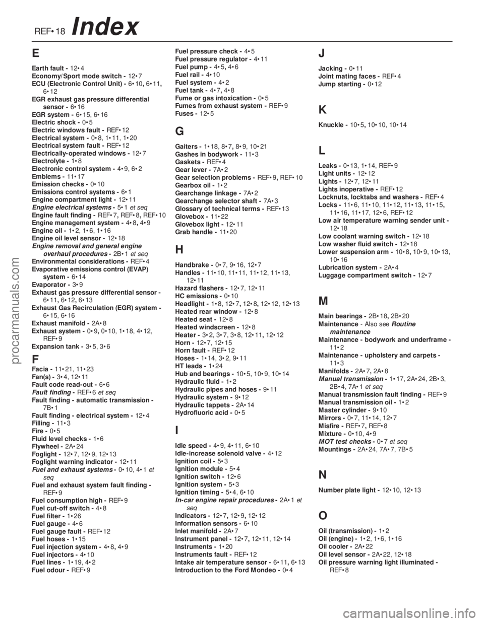
REF•18Index
E
Earth fault - 12•4
Economy/Sport mode switch - 12•7
ECU (Electronic Control Unit) - 6•10, 6•11,
6•12
EGR exhaust gas pressure differential
sensor - 6•16
EGR system - 6•15, 6•16
Electric shock - 0•5
Electric windows fault - REF•12
Electrical system - 0•8, 1•11, 1•20
Electrical system fault - REF•12
Electrically-operated windows - 12•7
Electrolyte - 1•8
Electronic control system - 4•9, 6•2
Emblems - 11•17
Emission checks - 0•10
Emissions control systems - 6•1
Engine compartment light - 12•11
Engine electrical systems- 5•1et seq
Engine fault finding - REF•7, REF•8, REF•10
Engine management system - 4•8, 4•9
Engine oil - 1•2, 1•6, 1•16
Engine oil level sensor - 12•18
Engine removal and general engine
overhaul procedures- 2B•1et seq
Environmental considerations - REF•4
Evaporative emissions control (EVAP)
system - 6•14
Evaporator - 3•9
Exhaust gas pressure differential sensor -
6•11, 6•12, 6•13
Exhaust Gas Recirculation (EGR) system -
6•15, 6•16
Exhaust manifold - 2A•8
Exhaust system - 0•9, 0•10, 1•18, 4•12,
REF•9
Expansion tank - 3•5, 3•6
FFacia - 11•21, 11•23
Fan(s) - 3•4, 12•11
Fault code read-out - 6•6
Fault finding- REF•6et seq
Fault finding - automatic transmission -
7B•1
Fault finding - electrical system - 12•4
Filling - 11•3
Fire - 0•5
Fluid level checks - 1•6
Flywheel - 2A•24
Foglight - 12•7, 12•9, 12•13
Foglight warning indicator - 12•11
Fuel and exhaust systems- 0•10, 4•1et
seq
Fuel and exhaust system fault finding -
REF•9
Fuel consumption high - REF•9
Fuel cut-off switch - 4•8
Fuel filter - 1•26
Fuel gauge - 4•6
Fuel gauge fault - REF•12
Fuel hoses - 1•15
Fuel injection system - 4•8, 4•9
Fuel injectors - 4•10
Fuel lines - 1•19, 4•2
Fuel odour - REF•9Fuel pressure check - 4•5
Fuel pressure regulator - 4•11
Fuel pump - 4•5, 4•6
Fuel rail - 4•10
Fuel system - 4•2
Fuel tank - 4•7, 4•8
Fume or gas intoxication - 0•5
Fumes from exhaust system - REF•9
Fuses - 12•5
G
Gaiters - 1•18, 8•7, 8•9, 10•21
Gashes in bodywork - 11•3
Gaskets - REF•4
Gear lever - 7A•2
Gear selection problems - REF•9, REF•10
Gearbox oil - 1•2
Gearchange linkage - 7A•2
Gearchange selector shaft - 7A•3
Glossary of technical terms - REF•13
Glovebox - 11•22
Glovebox light - 12•11
Grab handle - 11•20
H
Handbrake - 0•7, 9•16, 12•7
Handles - 11•10, 11•11, 11•12, 11•13,
12•11
Hazard flashers - 12•7, 12•11
HC emissions - 0•10
Headlight - 1•8, 12•7, 12•8, 12•12, 12•13
Heated rear window - 12•8
Heated seat - 12•8
Heated windscreen - 12•8
Heater - 3•2, 3•7, 3•8, 12•11, 12•12
Horn - 12•7, 12•15
Horn fault - REF•12
Hoses - 1•14, 3•2, 9•11
HT leads - 1•24
Hub and bearings - 10•5, 10•9, 10•14
Hydraulic fluid - 1•2
Hydraulic pipes and hoses - 9•11
Hydraulic system - 9•12
Hydraulic tappets - 2A•14
Hydrofluoric acid - 0•5
I
Idle speed - 4•9, 4•11, 6•10
Idle-increase solenoid valve - 4•12
Ignition coil - 5•3
Ignition module - 5•4
Ignition switch - 12•6
Ignition system - 5•3
Ignition timing - 5•4, 6•10
In-car engine repair procedures- 2A•1et
seq
Indicators - 12•7, 12•9, 12•12
Information sensors - 6•10
Inlet manifold - 2A•7
Instrument panel - 12•7, 12•11, 12•14
Instruments - 1•20
Instruments fault - REF•12
Intake air temperature sensor - 6•11, 6•13
Introduction to the Ford Mondeo - 0•4
J
Jacking - 0•11
Joint mating faces - REF•4
Jump starting - 0•12
K
Knuckle - 10•5, 10•10, 10•14
L
Leaks - 0•13, 1•14, REF•9
Light units - 12•12
Lights - 12•7, 12•11
Lights inoperative - REF•12
Locknuts, locktabs and washers - REF•4
Locks - 11•6, 11•10, 11•12, 11•13, 11•15,
11•16, 11•17, 12•6, REF•12
Low air temperature warning sender unit -
12•18
Low coolant warning switch - 12•18
Low washer fluid switch - 12•18
Lower suspension arm - 10•8, 10•9, 10•13,
10•16
Lubrication system - 2A•4
Luggage compartment switch - 12•7
M
Main bearings - 2B•18, 2B•20
Maintenance- Also see Routine
maintenance
Maintenance - bodywork and underframe -
11•2
Maintenance - upholstery and carpets -
11•3
Manifolds - 2A•7, 2A•8
Manual transmission- 1•17, 2A•24, 2B•3,
2B•4, 7A•1et seq
Manual transmission fault finding - REF•9
Manual transmission oil - 1•2
Master cylinder - 9•10
Mirrors - 0•7, 11•14, 12•7
Misfire - REF•7, REF•8
Mixture - 0•10, 4•9
MOT test checks- 0•7et seq
Mountings - 2A•24, 7A•7, 7B•5
N
Number plate light - 12•10, 12•13
O
Oil (transmission) - 1•2
Oil (engine) - 1•2, 1•6, 1•16
Oil cooler - 2A•22
Oil level sensor - 2A•22, 12•18
Oil pressure warning light illuminated -
REF•8
procarmanuals.com
Page 278 of 279
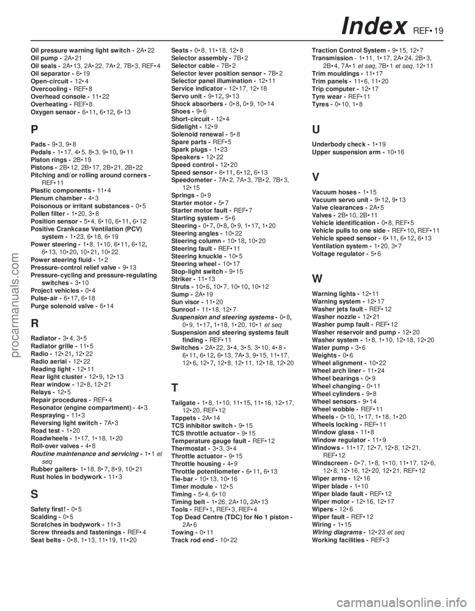
REF•19Index
Oil pressure warning light switch - 2A•22
Oil pump - 2A•21
Oil seals - 2A•13, 2A•22, 7A•2, 7B•3, REF•4
Oil separator - 6•19
Open-circuit - 12•4
Overcooling - REF•8
Overhead console - 11•22
Overheating - REF•8
Oxygen sensor - 6•11, 6•12, 6•13
P
Pads - 9•3, 9•8
Pedals - 1•17, 4•5, 8•3, 9•10, 9•11
Piston rings - 2B•19
Pistons - 2B•12, 2B•17, 2B•21, 2B•22
Pitching and/or rolling around corners -
REF•11
Plastic components - 11•4
Plenum chamber - 4•3
Poisonous or irritant substances - 0•5
Pollen filter - 1•20, 3•8
Position sensor - 5•4, 6•10, 6•11, 6•12
Positive Crankcase Ventilation (PCV)
system - 1•23, 6•18, 6•19
Power steering - 1•8, 1•10, 6•11, 6•12,
6•13, 10•20, 10•21, 10•22
Power steering fluid - 1•2
Pressure-control relief valve - 9•13
Pressure-cycling and pressure-regulating
switches - 3•10
Project vehicles - 0•4
Pulse-air - 6•17, 6•18
Purge solenoid valve - 6•14
R
Radiator - 3•4, 3•5
Radiator grille - 11•5
Radio - 12•21, 12•22
Radio aerial - 12•22
Reading light - 12•11
Rear light cluster - 12•9, 12•13
Rear window - 12•8, 12•21
Relays - 12•5
Repair procedures - REF•4
Resonator (engine compartment) - 4•3
Respraying - 11•3
Reversing light switch - 7A•3
Road test - 1•20
Roadwheels - 1•17, 1•18, 1•20
Roll-over valves - 4•8
Routine maintenance and servicing- 1•1et
seq
Rubber gaiters- 1•18, 8•7, 8•9, 10•21
Rust holes in bodywork - 11•3
S
Safety first! - 0•5
Scalding - 0•5
Scratches in bodywork - 11•3
Screw threads and fastenings - REF•4
Seat belts - 0•8, 1•13, 11•19, 11•20Seats - 0•8, 11•18, 12•8
Selector assembly - 7B•2
Selector cable - 7B•2
Selector lever position sensor - 7B•2
Selector panel illumination - 12•11
Service indicator - 12•17, 12•18
Servo unit - 9•12, 9•13
Shock absorbers - 0•8, 0•9, 10•14
Shoes - 9•6
Short-circuit - 12•4
Sidelight - 12•9
Solenoid renewal - 5•8
Spare parts - REF•5
Spark plugs - 1•23
Speakers - 12•22
Speed control - 12•20
Speed sensor - 6•11, 6•12, 6•13
Speedometer - 7A•2, 7A•3, 7B•2, 7B•3,
12•15
Springs - 0•9
Starter motor - 5•7
Starter motor fault - REF•7
Starting system - 5•6
Steering - 0•7, 0•8, 0•9, 1•17, 1•20
Steering angles - 10•22
Steering column - 10•18, 10•20
Steering fault - REF•11
Steering knuckle - 10•5
Steering wheel - 10•17
Stop-light switch - 9•15
Striker - 11•13
Struts - 10•6, 10•7, 10•10, 10•12
Sump - 2A•19
Sun visor - 11•20
Sunroof - 11•18, 12•7
Suspension and steering systems- 0•8,
0•9, 1•17, 1•18, 1•20, 10•1et seq
Suspension and steering systems fault
finding - REF•11
Switches - 2A•22, 3•4, 3•5, 3•10, 4•8-
6•11, 6•12, 6•13, 7A•3, 9•15, 11•17,
12•6, 12•7, 12•8, 12•11, 12•18, 12•20
T
Tailgate - 1•8, 1•10, 11•15, 11•16, 12•17,
12•20, REF•12
Tappets - 2A•14
TCS inhibitor switch - 9•15
TCS throttle actuator - 9•15
Temperature gauge fault - REF•12
Thermostat - 3•3, 3•4
Throttle actuator - 9•15
Throttle housing - 4•9
Throttle potentiometer - 6•11, 6•13
Tie-bar - 10•13, 10•16
Timer module - 12•5
Timing - 5•4, 6•10
Timing belt - 1•26, 2A•10, 2A•13
Tools - REF•1, REF•3, REF•4
Top Dead Centre (TDC) for No 1 piston -
2A•6
Towing - 0•11
Track rod end - 10•22Traction Control System - 9•15, 12•7
Transmission- 1•11, 1•17, 2A•24, 2B•3,
2B•4, 7A•1 et seq, 7B•1 et seq, 12•11
Trim mouldings - 11•17
Trim panels - 11•6, 11•20
Trip computer - 12•17
Tyre wear - REF•11
Tyres - 0•10, 1•8
U
Underbody check - 1•19
Upper suspension arm - 10•16
V
Vacuum hoses - 1•15
Vacuum servo unit - 9•12, 9•13
Valve clearances - 2A•5
Valves - 2B•10, 2B•11
Vehicle identification - 0•8, REF•5
Vehicle pulls to one side - REF•10, REF•11
Vehicle speed sensor - 6•11, 6•12, 6•13
Ventilation system - 1•20, 3•7
Voltage regulator - 5•6
W
Warning lights - 12•11
Warning system - 12•17
Washer jets fault - REF•12
Washer nozzle - 12•21
Washer pump fault - REF•12
Washer reservoir and pump - 12•20
Washer system - 1•8, 1•10, 12•18, 12•20
Water pump - 3•6
Weights - 0•6
Wheel alignment - 10•22
Wheel arch liner - 11•24
Wheel bearings - 0•9
Wheel changing - 0•11
Wheel cylinders - 9•8
Wheel sensors - 9•14
Wheel wobble - REF•11
Wheels - 0•10, 1•17, 1•18, 1•20
Wheels locking - REF•11
Window glass - 11•8
Window regulator - 11•9
Windows - 11•17, 12•7, 12•8, 12•21,
REF•12
Windscreen - 0•7, 1•8, 1•10, 11•17, 12•6,
12•8, 12•16, 12•20, 12•21, REF•12
Wiper arms - 12•16
Wiper blade - 1•10
Wiper blade fault - REF•12
Wiper motor - 12•16, 12•17
Wipers - 12•6
Wiper fault - REF•12
Wiring - 1•15
Wiring diagrams- 12•23et seq
Working facilities - REF•3
procarmanuals.com