belt FORD MONDEO 1993 Service Workshop Manual
[x] Cancel search | Manufacturer: FORD, Model Year: 1993, Model line: MONDEO, Model: FORD MONDEO 1993Pages: 279, PDF Size: 12.71 MB
Page 144 of 279
Ignition timing and base idle
speed check
Note:The following procedure is a check only,
essentially of the ECU. Both the ignition timing
and the base idle speed are controlled by the
ECU. The ignition timing is not adjustable at
all; the base idle speed is set in production,
and should not be altered.
38If the fault code read-out (with any checks
resulting from it) has not eliminated the fault,
the next step is to check the ECU’s control of
the ignition timing and the base idle speed.
This task requires the use of a Ford STAR
tester (a proprietary fault code reader can be
used only if it is capable of inducing the ECU
to enter its “Service Adjustment Programme”),
coupled with an accurate tachometer and a
good-quality timing light. Without this
equipment, the task is not possible; the
vehicle must be taken to a Ford dealer for
attention.
39To make the check, apply the handbrake,
switch off the air conditioning (where fitted)
and any other electrical loads (lights, heated
rear window, etc), then select neutral (manual
transmission) or the “P” position (automatic
transmission). Start the engine, and warm it
up to normal operating temperature. The
radiator electric cooling fan must be running
continuously while the check is made; this
should be activated by the ECU, when
prompted by the tester. Switch off the engine,
and connect the test equipment as directed
by the manufacturer - refer to paragraph 26
above for details of STAR tester connection.
40Raise and support the front of the vehicle
securely, and remove the auxiliary drivebelt
cover (see Chapter 1). Emphasise the two
pairs of notches in the inner and outer rims of
the crankshaft pulley, using white paint. Note
that an ignition timing reference mark is not
provided on the pulley - in the normal
direction of crankshaft rotation (clockwise,
seen from the right-hand side of the vehicle)
the first pair of notches are irrelevant to the
vehicles covered in this manual, while the
second pair indicate Top Dead Centre (TDC)
when aligned with the rear edge of the raised
mark on the sump; when checking the ignition
timing, therefore, the (rear edge of the) sumpmark should appear just before the TDC
notches (see Part A of Chapter 2, Section 4,
for further information if required).
41Start the engine and allow it to idle. Work
through the engine-running test procedure
until the ECU enters its “Service Adjustment
Programme” - see paragraph 35 above.
42Use the timing light to check that the
timing marks appear approximately as
outlined above at idle speed. Do not spend
too much time on this check; if the timing
appears to be incorrect, the system may have
a fault, and a full system test must be carried
out (see below) to establish its cause.
43Using the tachometer, check that the
base idle speed is as given in the
Specifications Section of Chapter 4.
44If the recorded speed differs significantly
from the specified value, check for air leaks,
as described in the preliminary checks
(paragraphs 15 to 18 above), or any other
faults which might cause the discrepancy.
45The base idle speed is set in production
by means of an air bypass screw (located in
the front right-hand corner of the throttle
housing) which controls the amount of air that
is allowed to pass through a bypass passage,
past the throttle valve when it is fully closed in
the idle position; the screw is then sealed with
a white tamperproof plug (see illustration). In
service, the idle speed is controlled by the
ECU, which has the ability to compensate for
engine wear, build-up of dirt in the throttle
housing, and other factors which might
require changes in idle speed. The air bypass
screw setting should not, therefore, be
altered. If any alterations are made, a blue
tamperproof plug must be fitted, and the
engine should be allowed to idle for at least
five minutes on completion, so that the ECU
can re-learn its idle values.
46When both checks have been made and
the “Service Adjustment Programme” is
completed, follow the tester instructions to
return to the fault code read-out, and
establish whether the fault has been cured or
not.
Basic check of ignition system
47If the checks so far have not eliminated
the fault, the next step is to carry out a basic
check of the ignition system components,
using an engine analyser with an oscilloscope
- without such equipment, the only tests
possible are to remove and check each spark
plug in turn, to check the spark plug (HT) lead
connections and resistances, and to check
the connections and resistances of the
ignition coil. Refer to the relevant Sections of
Chapters 1 and 5.
Basic check of fuel system
48If the checks so far have not eliminated
the fault, the next step is to carry out a basic
check of the fuel system components.
49Assuming that the preliminary checks
have established that the fuel pump is
operating correctly, that the fuel filter isunlikely to be blocked, and also that there are
no leaks in the system, the next step is to
check the fuel pressure (see Chapter 4). If this
is correct, check the injectors (see Chapter 4)
and the Positive Crankcase Ventilation system
(see Chapter 1).
System test
50The final element of the Ford testing
procedure is to carry out a system test, using
a break-out box - this is a device that is
connected between the ECU and its electrical
connector, so that the individual circuits
indicated by the fault code read-out can be
tested while connected to the system, if
necessary with the engine running. In the case
of many of the system’s components, this
enables their output voltages to be measured
- a more accurate means of testing.
51In addition to the break-out box and the
adaptors required to connect it, several items
of specialist equipment are needed to
complete these tests. This puts them quite
beyond the scope of many smaller dealers, let
alone the DIY owner; the vehicle should be
taken to a Ford dealer for attention.
Note:This Section is concerned principally
with the sensors which give the ECU the
information it needs to control the various
engine management sub-systems - for further
details of those systems and their other
components, refer to the relevant Chapter of
this manual.
General
ECU (Electronic Control Unit)
1This component is the heart of the entire
engine management system, controlling the
fuel injection, ignition and emissions control
systems. It also controls sub-systems such as
the radiator cooling fan, air conditioning and
automatic transmission, where appropriate.
Refer to Section 2 of this Chapter for an
illustration of how it works.
Air mass meter
2This uses a “hot-wire” system, sending the
ECU a constantly-varying (analogue) voltage
signal corresponding to the mass of air
passing into the engine. Since air mass varies
with temperature (cold air being denser than
warm), measuring air mass provides the ECU
with a very accurate means of determining the
correct amount of fuel required to achieve the
ideal air/fuel mixture ratio.
Crankshaft speed/position sensor
3This is an inductive pulse generator bolted
(in a separate bracket) to the cylinder
block/crankcase, to scan the ridges between
36 holes machined in the inboard (right-hand)
face of the flywheel/driveplate. As each ridge
4 Information sensors -
general information, testing,
removal and refitting
6•10 Emissions control systems
3.45 Throttle housing air bypass screw is
sealed on production with a white
tamperproof plug (arrowed)
procarmanuals.com
Page 162 of 279
spring must now be carefully released from
the compressor. If it is to be re-used, the
spring can be left in compression.
7With the strut assembly now completely
dismantled, examine all the components for
wear and damage, and check the bearing for
smoothness of operation. Renew components
as necessary.
8Examine the strut for signs of fluid leakage.
Check the strut piston for signs of pitting
along its entire length, and check the strut
body for signs of damage. Test the operation
of the strut, while holding it in an upright
position, by moving the piston through a full
stroke, and then through short strokes of 50
to 100 mm. In both cases, the resistance felt
should be smooth and continuous. If the
resistance is jerky, uneven, or if there is any
visible sign of wear or damage to the strut,
renewal is necessary.
9Reassembly is a reversal of dismantling,
noting the following points:
(a) Make sure that the coil spring ends are
correctly located in the upper and lower
seats before releasing the compressor.
(b) Check that the bearing is correctly fitted
to the piston rod seat.
(c) Tighten the thrust bearing retaining nut to
the specified torque.
Removal
1Apply the handbrake, jack up the front of
the vehicle and support it on axle stands.
Remove both front wheels.
2Unscrew the nuts, and disconnect the anti-
roll bar links from the front suspension struts
on both sides of the vehicle. Note that, on
models with ABS, the wheel sensor wiring
support brackets are located beneath the nuts
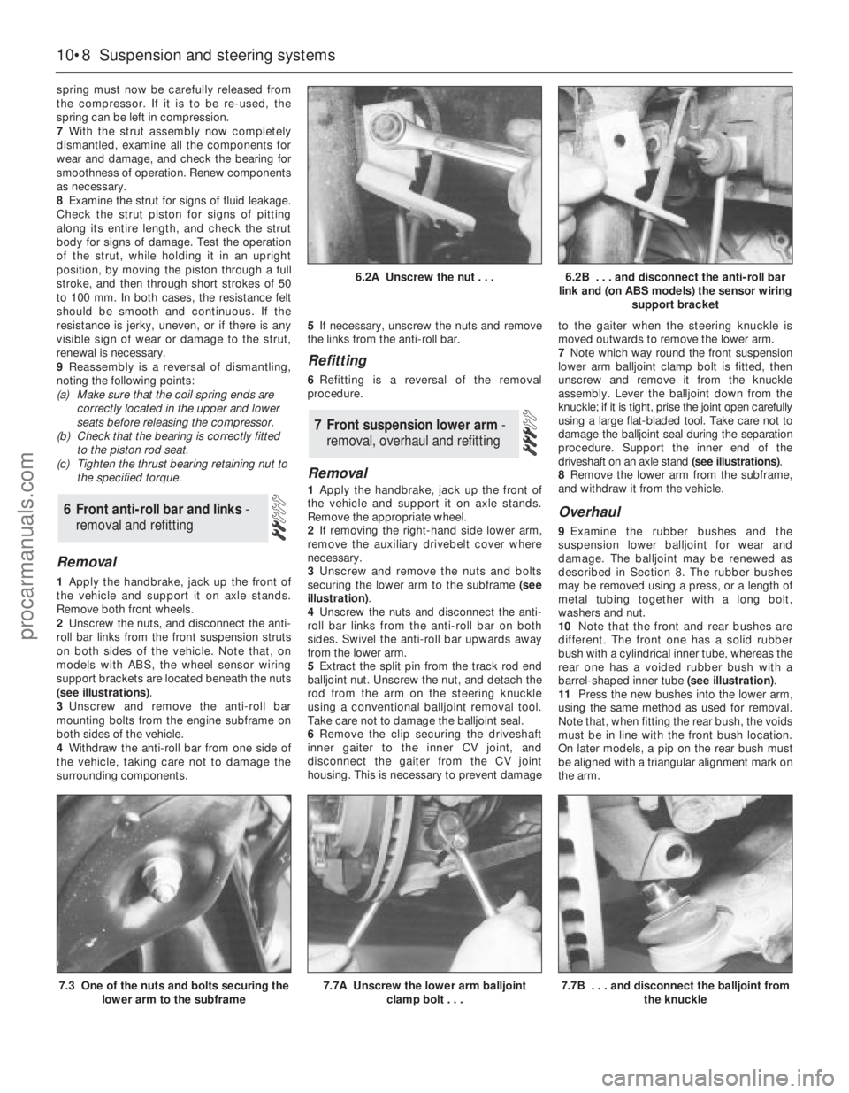
(see illustrations).
3Unscrew and remove the anti-roll bar
mounting bolts from the engine subframe on
both sides of the vehicle.
4Withdraw the anti-roll bar from one side of
the vehicle, taking care not to damage the
surrounding components.5If necessary, unscrew the nuts and remove
the links from the anti-roll bar.
Refitting
6Refitting is a reversal of the removal
procedure.
Removal
1Apply the handbrake, jack up the front of
the vehicle and support it on axle stands.
Remove the appropriate wheel.
2If removing the right-hand side lower arm,
remove the auxiliary drivebelt cover where
necessary.
3Unscrew and remove the nuts and bolts
securing the lower arm to the subframe (see
illustration).
4Unscrew the nuts and disconnect the anti-
roll bar links from the anti-roll bar on both
sides. Swivel the anti-roll bar upwards away
from the lower arm.
5Extract the split pin from the track rod end
balljoint nut. Unscrew the nut, and detach the
rod from the arm on the steering knuckle
using a conventional balljoint removal tool.
Take care not to damage the balljoint seal.
6Remove the clip securing the driveshaft
inner gaiter to the inner CV joint, and
disconnect the gaiter from the CV joint
housing. This is necessary to prevent damageto the gaiter when the steering knuckle is
moved outwards to remove the lower arm.
7Note which way round the front suspension
lower arm balljoint clamp bolt is fitted, then
unscrew and remove it from the knuckle
assembly. Lever the balljoint down from the
knuckle; if it is tight, prise the joint open carefully
using a large flat-bladed tool. Take care not to
damage the balljoint seal during the separation
procedure. Support the inner end of the
driveshaft on an axle stand (see illustrations).
8Remove the lower arm from the subframe,
and withdraw it from the vehicle.
Overhaul
9Examine the rubber bushes and the
suspension lower balljoint for wear and
damage. The balljoint may be renewed as
described in Section 8. The rubber bushes
may be removed using a press, or a length of
metal tubing together with a long bolt,
washers and nut.
10Note that the front and rear bushes are
different. The front one has a solid rubber
bush with a cylindrical inner tube, whereas the
rear one has a voided rubber bush with a
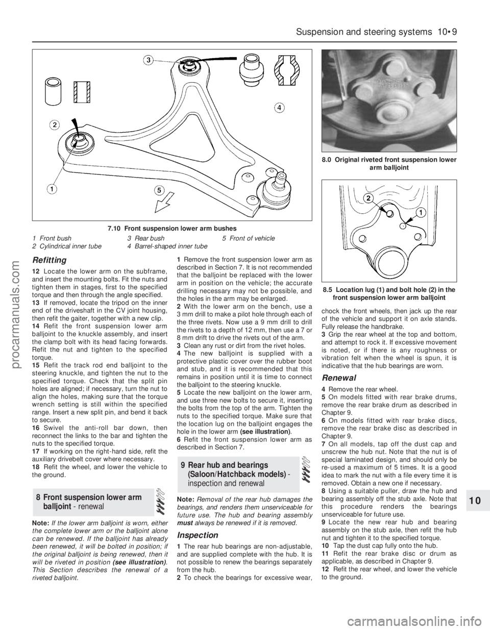
barrel-shaped inner tube (see illustration).
11Press the new bushes into the lower arm,
using the same method as used for removal.
Note that, when fitting the rear bush, the voids
must be in line with the front bush location.
On later models, a pip on the rear bush must
be aligned with a triangular alignment mark on
the arm.
7 Front suspension lower arm -
removal, overhaul and refitting
6 Front anti-roll bar and links -
removal and refitting
10•8 Suspension and steering systems
6.2A Unscrew the nut . . .6.2B . . . and disconnect the anti-roll bar
link and (on ABS models) the sensor wiring
support bracket
7.3 One of the nuts and bolts securing the
lower arm to the subframe7.7A Unscrew the lower arm balljoint
clamp bolt . . .7.7B . . . and disconnect the balljoint from
the knuckle
procarmanuals.com
Page 163 of 279
Refitting
12Locate the lower arm on the subframe,
and insert the mounting bolts. Fit the nuts and
tighten them in stages, first to the specified
torque and then through the angle specified.
13If removed, locate the tripod on the inner
end of the driveshaft in the CV joint housing,
then refit the gaiter, together with a new clip.
14Refit the front suspension lower arm
balljoint to the knuckle assembly, and insert
the clamp bolt with its head facing forwards.
Refit the nut and tighten to the specified
torque.
15Refit the track rod end balljoint to the
steering knuckle, and tighten the nut to the
specified torque. Check that the split pin
holes are aligned; if necessary, turn the nut to
align the holes, making sure that the torque
wrench setting is still within the specified
range. Insert a new split pin, and bend it back
to secure.
16Swivel the anti-roll bar down, then
reconnect the links to the bar and tighten the
nuts to the specified torque.
17If working on the right-hand side, refit the
auxiliary drivebelt cover where necessary.
18Refit the wheel, and lower the vehicle to
the ground.
Note:If the lower arm balljoint is worn, either
the complete lower arm or the balljoint alone
can be renewed. If the balljoint has already
been renewed, it will be bolted in position; if
the original balljoint is being renewed, then it
will be riveted in position (see illustration).
This Section describes the renewal of a
riveted balljoint.1Remove the front suspension lower arm as
described in Section 7. It is not recommended
that the balljoint be replaced with the lower
arm in position on the vehicle; the accurate
drilling necessary may not be possible, and
the holes in the arm may be enlarged.
2With the lower arm on the bench, use a
3 mm drill to make a pilot hole through each of
the three rivets. Now use a 9 mm drill to drill
the rivets to a depth of 12 mm, then use a 7 or
8 mm drift to drive the rivets out of the arm.
3Clean any rust or dirt from the rivet holes.
4The new balljoint is supplied with a
protective plastic cover over the rubber boot
and stub, and it is recommended that this
remains in position until it is time to connect
the balljoint to the steering knuckle.
5Locate the new balljoint on the lower arm,
and use three new bolts to secure it, inserting
the bolts from the top of the arm. Tighten the
nuts to the specified torque. Make sure that
the location lug on the balljoint engages the
hole in the lower arm (see illustration).
6Refit the front suspension lower arm as
described in Section 7.
Note:Removal of the rear hub damages the
bearings, and renders them unserviceable for
future use. The hub and bearing assembly
mustalways be renewed if it is removed.
Inspection
1The rear hub bearings are non-adjustable,
and are supplied complete with the hub. It is
not possible to renew the bearings separately
from the hub.
2To check the bearings for excessive wear,chock the front wheels, then jack up the rear
of the vehicle and support it on axle stands.
Fully release the handbrake.
3Grip the rear wheel at the top and bottom,
and attempt to rock it. If excessive movement
is noted, or if there is any roughness or
vibration felt when the wheel is spun, it is
indicative that the hub bearings are worn.
Renewal
4Remove the rear wheel.
5On models fitted with rear brake drums,
remove the rear brake drum as described in
Chapter 9.
6On models fitted with rear brake discs,
remove the rear brake disc as described in
Chapter 9.
7On all models, tap off the dust cap and
unscrew the hub nut. Note that the nut is of
special laminated design, and should only be
re-used a maximum of 5 times. It is a good
idea to mark the nut with a file every time it is
removed. Obtain a new one if necessary.
8Using a suitable puller, draw the hub and
bearing assembly off the stub axle. Note that
this procedure renders the bearings
unserviceable for future use.
9Locate the new rear hub and bearing
assembly on the stub axle, then refit the hub
nut and tighten it to the specified torque.
10Tap the dust cap fully onto the hub.
11Refit the rear brake disc or drum as
applicable, as described in Chapter 9.
12Refit the rear wheel, and lower the vehicle
to the ground.
9 Rear hub and bearings
(Saloon/Hatchback models)-
inspection and renewal
8 Front suspension lower arm
balljoint - renewal
Suspension and steering systems 10•9
10
7.10 Front suspension lower arm bushes
1 Front bush
2 Cylindrical inner tube3 Rear bush
4 Barrel-shaped inner tube5 Front of vehicle
8.5 Location lug (1) and bolt hole (2) in the
front suspension lower arm balljoint
8.0 Original riveted front suspension lower
arm balljoint
procarmanuals.com
Page 176 of 279
3Start the engine, and allow it to run at a fast
idle. Check the hoses and connections for
leaks.
4Stop the engine, and recheck the fluid level.
Add more if necessary, up to the “MAX” or
“MAX COLD” mark.
5Start the engine again, allow it to idle, then
bleed the system by slowly turning the
steering wheel from side to side several times.
This should purge the system of all internal
air. However, if air remains in the system
(indicated by the steering operation being very
noisy), leave the vehicle overnight, and repeat
the procedure again the next day.
6If air still remains in the system, it may be
necessary to resort to the Ford method of
bleeding, which uses a vacuum pump. Turn
the steering to the right until it is near the stop,
then fit the vacuum pump to the fluid
reservoir, and apply 0.15 bars of vacuum.
Maintain the vacuum for a minimum of
5 minutes, then repeat the procedure with the
steering turned to the left.
7Keep the fluid level topped-up throughout
the bleeding procedure; note that, as the fluid
temperature increases, the level will rise.
8On completion, switch off the engine, and
return the front wheels to the straight-ahead
position.
Removal
1Disconnect the battery negative (earth) lead
(refer to Chapter 5, Section 1).
2Unscrew and remove the bolt securing the
hydraulic fluid line support to the engine lifting
bracket on the right-hand side of the engine.
3Unscrew and remove the bolt securing the
hydraulic fluid line support to the pump
mounting bracket.
4Position a suitable container beneath the
power steering pump, to catch spilt fluid.
5Loosen the clip, and disconnect the fluid
supply hose from the pump inlet. Plug the
hose, to prevent the ingress of dust and dirt.
6Unscrew the union nut, and disconnect the
high-pressure line from the pump. Allow the
fluid to drain into the container.
7Apply the handbrake, then jack up the front
of the vehicle and support it on axle stands.
Remove the right-hand front wheel.
8Unbolt and remove the lower drivebelt
cover.
9Using a spanner, rotate the drivebelt
tensioner in a clockwise direction to release
the belt tension, then slip the drivebelt off the
pulleys and remove from the vehicle. Refer to
Chapter 1 if necessary.
10Unscrew and remove the four mounting
bolts, and withdraw the power steering pump
from its bracket. Access to the bolts on the
right-hand side of the engine is gained by
turning the pump pulley until a hole lines up
with the bolt.
Refitting
11Locate the power steering pump on the
mounting bracket, and secure with the four
bolts. Tighten the bolts to the specified
torque.
12Slip the drivebelt over the pulleys, then
rotate the drivebelt tensioner in a clockwise
direction, and locate the drivebelt on it.
Release the tensioner to tension the drivebelt.
13Refit the lower belt cover.
14Refit the right-hand front wheel, and lower
the vehicle to the ground.
15If necessary, the sealing ring on the high-
pressure outlet should be renewed, using the
same procedure as described in Section 30,
paragraph 8.
16Reconnect the high-pressure line to the
pump, and tighten the union nut.
17Reconnect the fluid supply hose to the
pump inlet, and tighten the clip.
18Refit the hydraulic fluid line support to the
pump mounting bracket, and tighten the bolt.
19Refit the hydraulic fluid line support to the
engine lifting bracket on the right-hand side of
the engine, and tighten the bolt.
20Reconnect the battery negative lead.
21Bleed the power steering hydraulic
system as described in Section 33.
1Apply the handbrake, then jack up the front
of the vehicle and support it on axle stands.
Remove the appropriate front roadwheel.
2Using a suitable spanner, slacken the
locknut on the track rod by a quarter-turn.
Hold the track rod end stationary with another
spanner engaged with the special flats while
loosening the locknut.
3Extract the split pin, then unscrew and
remove the track rod end balljoint retaining
nut.
4To release the tapered shank of the balljoint
from the steering knuckle arm, use a balljoint
separator tool (if the balljoint is to be re-used,
take care not to damage the dust cover when
using the separator tool) (see illustration).
5Count the number of exposed threads
visible on the inner section of the track rod,
and record this figure.
6Unscrew the track rod end from the track
rod, counting the number of turns necessary
to remove it. If necessary, hold the track rod
stationary with grips.
Refitting
7Screw the track rod end onto the track rod
by the number of turns noted during removal,
until it just contacts the locknut.
8Engage the shank of the balljoint with the
steering knuckle arm, and refit the nut.
Tighten the nut to the specified torque. If the
balljoint shank turns while the nut is being
tightened, press down on the balljoint. The
tapered fit of the shank will lock it, and
prevent rotation as the nut is tightened.9Check that the split pin holes in the nut and
balljoint shank are aligned. If necessary turn
the nut to the nearest alignment, making sure
that the torque wrench setting is still within
the specified range. Insert a new split pin, and
bend it back to secure.
10Now tighten the locknut, while holding the
track rod end as before.
11Refit the roadwheel, and lower the vehicle
to the ground.
12Finally check, and if necessary adjust, the
front wheel alignment as described in Sec-
tion 29.
1Accurate front wheel alignment is essential
to provide positive steering, and to prevent
excessive tyre wear. Before considering the
steering/suspension geometry, check that the
tyres are correctly inflated, that the front
wheels are not buckled, and that the steering
linkage and suspension joints are in good
order, without slackness or wear.
2Wheel alignment consists of four factors
(see illustration):
Camberis the angle at which the front
wheels are set from the vertical, when viewed
from the front of the vehicle. “Positive
camber” is the amount (in degrees) that the
wheels are tilted outward at the top of the
vertical. Castoris the angle between the
steering axis and a vertical line, when viewed
from each side of the car. “Positive castor” is
when the steering axis is inclined rearward at
the top.
Steering axis inclinationis the angle (when
viewed from the front of the vehicle) between
the vertical and an imaginary line drawn
through the suspension strut upper mounting
and the lower suspension arm balljoint.
Toe settingis the amount by which the
distance between the front inside edges of the
roadwheels (measured at hub height) differs
from the diametrically-opposite distance
measured between the rear inside edges of
the front roadwheels.
3With the exception of the toe setting, all
other steering angles are set during
manufacture, and no adjustment is possible. It
36 Wheel alignment and steering
angles - general information35 Track rod end - renewal34 Power steering pump -
removal and refitting
10•22 Suspension and steering systems
35.4 Using a balljoint separator tool to
release the track rod end balljoint
procarmanuals.com
Page 178 of 279
Chapter 11 Bodywork and fittings
Body side-trim mouldings and adhesive emblems - removal
and refitting . . . . . . . . . . . . . . . . . . . . . . . . . . . . . . . . . . . . . . . . . . 25
Bonnet - removal, refitting and adjustment . . . . . . . . . . . . . . . . . . . . 8
Bonnet lock - removal, refitting and adjustment . . . . . . . . . . . . . . . . 10
Bonnet release cable and lever - removal and refitting . . . . . . . . . . . 9
Boot lid - removal and refitting . . . . . . . . . . . . . . . . . . . . . . . . . . . . . 18
Boot lid lock components - removal and refitting . . . . . . . . . . . . . . . 19
Bumpers - removal and refitting . . . . . . . . . . . . . . . . . . . . . . . . . . . . 6
Central locking system components - testing, removal and refitting . 23
Centre console - removal and refitting . . . . . . . . . . . . . . . . . . . . . . . 30
Door - removal and refitting . . . . . . . . . . . . . . . . . . . . . . . . . . . . . . . 15
Door handle and lock components - removal and refitting . . . . . . . . 14
Door inner trim panel - removal and refitting . . . . . . . . . . . . . . . . . . 11
Door window glass - removal and refitting . . . . . . . . . . . . . . . . . . . . 12
Door window regulator - removal and refitting . . . . . . . . . . . . . . . . . 13
Exterior mirror and glass - removal and refitting . . . . . . . . . . . . . . . . 16
Facia - removal and refitting . . . . . . . . . . . . . . . . . . . . . . . . . . . . . . . 33
General information . . . . . . . . . . . . . . . . . . . . . . . . . . . . . . . . . . . . . . 1Glovebox - removal and refitting . . . . . . . . . . . . . . . . . . . . . . . . . . . . 32
Interior mirror - removal and refitting . . . . . . . . . . . . . . . . . . . . . . . . 17
Interior trim panels - removal and refitting . . . . . . . . . . . . . . . . . . . . 29
Maintenance - bodywork and underframe . . . . . . . . . . . . . . . . . . . . 2
Maintenance - upholstery and carpets . . . . . . . . . . . . . . . . . . . . . . . 3
Major body damage - repair . . . . . . . . . . . . . . . . . . . . . . . . . . . . . . . 5
Minor body damage - repair . . . . . . . . . . . . . . . . . . . . . . . . . . . . . . . 4
Overhead console - removal and refitting . . . . . . . . . . . . . . . . . . . . . 31
Radiator grille - removal and refitting . . . . . . . . . . . . . . . . . . . . . . . . 7
Seat belts - removal and refitting . . . . . . . . . . . . . . . . . . . . . . . . . . . 28
Seats - removal and refitting . . . . . . . . . . . . . . . . . . . . . . . . . . . . . . . 27
Sunroof - general information and adjustment . . . . . . . . . . . . . . . . . 26
Tailgate - removal and refitting . . . . . . . . . . . . . . . . . . . . . . . . . . . . . 20
Tailgate lock components - removal and refitting . . . . . . . . . . . . . . . 22
Tailgate support strut - removal and refitting . . . . . . . . . . . . . . . . . . 21
Wheel arch liner - removal and refitting . . . . . . . . . . . . . . . . . . . . . . 34
Windscreen and fixed windows - removal and refitting . . . . . . . . . . 24
Torque wrench settingsNm lbf ft
Bonnet and tailgate hinges . . . . . . . . . . . . . . . . . . . . . . . . . . . . . . . . . . . 24 18
Boot lid . . . . . . . . . . . . . . . . . . . . . . . . . . . . . . . . . . . . . . . . . . . . . . . . . . 10 7
Front seat mounting bolts . . . . . . . . . . . . . . . . . . . . . . . . . . . . . . . . . . . . 38 28
Seat belt mounting nuts and bolts . . . . . . . . . . . . . . . . . . . . . . . . . . . . . 38 28
Bumper mounting nuts . . . . . . . . . . . . . . . . . . . . . . . . . . . . . . . . . . . . . . 10 7
11•1
Easy,suitable for
novice with little
experienceFairly easy,suitable
for beginner with
some experienceFairly difficult,suitable
for competent DIY
mechanicDifficult,suitable for
experienced DIY
mechanicVery difficult,
suitable for expert DIY
or professional
Degrees of difficulty
Specifications Contents
11
The bodyshell and underframe on all
models is of all-steel welded construction,
incorporating progressive crumple zones at
the front and rear, and a rigid centre safety
cell. The bulkhead behind the engine
compartment incorporates crash grooves
which determine its energy-absorption
characteristics, and special beams to prevent
the intrusion of the front wheels into the
passenger compartment during a serious
accident. All passenger doors incorporate
side impact bars.
All sheet metal surfaces which are prone tocorrosion are galvanized. The painting
process includes a base colour which closely
matches the final topcoat, so that any stone
damage is not noticeable.
Hatchback, Saloon and Estate versions are
available. The front section of the vehicle up to
the “B” pillar is identical on all models.
Automatic seat belts are fitted to all models,
and the front seat belt stalks are mounted on
automatic tensioners (also known as
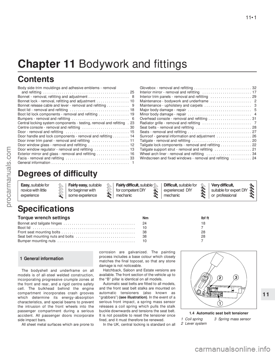
“grabbers”) (see illustration). In the event of a
serious front impact, a spring mass sensor
releases a coil spring which pulls the stalk
buckle downwards and tensions the seat belt.
It is not possible to reset the tensioner once
fired, and it must therefore be renewed.
In the UK, central locking is standard on all
1 General information
1.4 Automatic seat belt tensioner
1 Coil spring 3 Spring mass sensor
2 Lever system
procarmanuals.com
Page 195 of 279
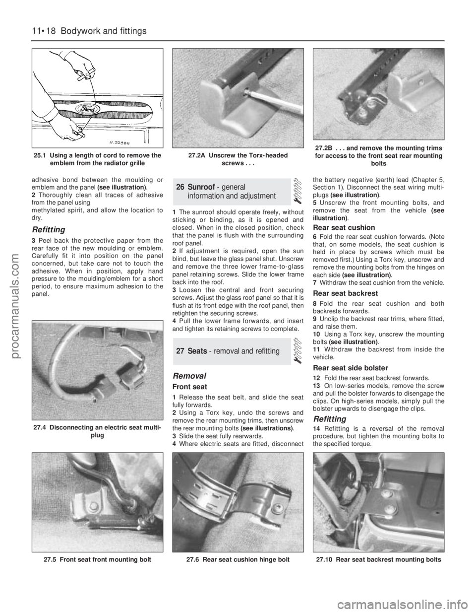
adhesive bond between the moulding or
emblem and the panel (see illustration).
2Thoroughly clean all traces of adhesive
from the panel using
methylated spirit, and allow the location to
dry.
Refitting
3Peel back the protective paper from the
rear face of the new moulding or emblem.
Carefully fit it into position on the panel
concerned, but take care not to touch the
adhesive. When in position, apply hand
pressure to the moulding/emblem for a short
period, to ensure maximum adhesion to the
panel.1The sunroof should operate freely, without
sticking or binding, as it is opened and
closed. When in the closed position, check
that the panel is flush with the surrounding
roof panel.
2If adjustment is required, open the sun
blind, but leave the glass panel shut. Unscrew
and remove the three lower frame-to-glass
panel retaining screws. Slide the lower frame
back into the roof.
3Loosen the central and front securing
screws. Adjust the glass roof panel so that it is
flush at its front edge with the roof panel, then
retighten the securing screws.
4Pull the lower frame forwards, and insert
and tighten its retaining screws to complete.
Removal
Front seat
1Release the seat belt, and slide the seat
fully forwards.
2Using a Torx key, undo the screws and
remove the rear mounting trims, then unscrew
the rear mounting bolts (see illustrations).
3Slide the seat fully rearwards.
4Where electric seats are fitted, disconnectthe battery negative (earth) lead (Chapter 5,
Section 1). Disconnect the seat wiring multi-
plugs (see illustration).
5Unscrew the front mounting bolts, and
remove the seat from the vehicle (see
illustration).
Rear seat cushion
6Fold the rear seat cushion forwards. (Note
that, on some models, the seat cushion is
held in place by screws which must be
removed first.) Using a Torx key, unscrew and
remove the mounting bolts from the hinges on
each side (see illustration).
7Withdraw the seat cushion from the vehicle.
Rear seat backrest
8Fold the rear seat cushion and both
backrests forwards.
9Unclip the backrest rear trims, where fitted,
and raise them.
10Using a Torx key, unscrew the mounting
bolts (see illustration).
11Withdraw the backrest from inside the
vehicle.
Rear seat side bolster
12Fold the rear seat backrest forwards.
13On low-series models, remove the screw
and pull the bolster forwards to disengage the
clips. On high-series models, simply pull the
bolster upwards to disengage the clips.
Refitting
14Refitting is a reversal of the removal
procedure, but tighten the mounting bolts to
the specified torque.
27 Seats - removal and refitting
26 Sunroof - general
information and adjustment
11•18 Bodywork and fittings
25.1 Using a length of cord to remove the
emblem from the radiator grille27.2A Unscrew the Torx-headed
screws . . .27.2B . . . and remove the mounting trims
for access to the front seat rear mounting
bolts
27.5 Front seat front mounting bolt
27.4 Disconnecting an electric seat multi-
plug
27.6 Rear seat cushion hinge bolt27.10 Rear seat backrest mounting bolts
procarmanuals.com
Page 196 of 279
Warning: Be careful when
handling the seat belt tensioning
device (“grabber”). It contains a
powerful spring, which could
cause injury if released in an uncontrolled
fashion. Once fired, the grabber cannot be
reset, and must be renewed. Note also
that seat belts and associated
components which have been subject to
impact loads must be renewed.
Removal
Front seat belt
1Remove the trim from the “B” pillar and the
scuttle.
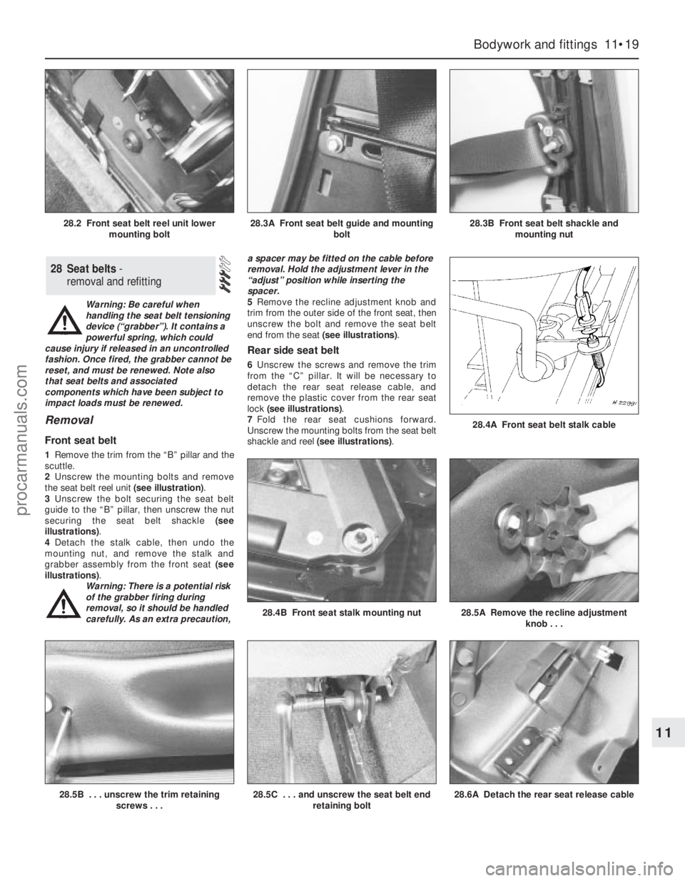
2Unscrew the mounting bolts and remove
the seat belt reel unit (see illustration).
3Unscrew the bolt securing the seat belt
guide to the “B” pillar, then unscrew the nut
securing the seat belt shackle (see
illustrations).
4Detach the stalk cable, then undo the
mounting nut, and remove the stalk and
grabber assembly from the front seat (see
illustrations).
Warning: There is a potential risk
of the grabber firing during
removal, so it should be handled
carefully. As an extra precaution,a spacer may be fitted on the cable before
removal. Hold the adjustment lever in the
“adjust” position while inserting the
spacer.
5Remove the recline adjustment knob and
trim from the outer side of the front seat, then
unscrew the bolt and remove the seat belt
end from the seat (see illustrations).
Rear side seat belt
6Unscrew the screws and remove the trim
from the “C” pillar. It will be necessary to
detach the rear seat release cable, and
remove the plastic cover from the rear seat
lock (see illustrations).
7Fold the rear seat cushions forward.
Unscrew the mounting bolts from the seat belt
shackle and reel (see illustrations).
28 Seat belts -
removal and refitting
Bodywork and fittings 11•19
11
28.5B . . . unscrew the trim retaining
screws . . .28.5C . . . and unscrew the seat belt end
retaining bolt28.6A Detach the rear seat release cable
28.4A Front seat belt stalk cable
28.4B Front seat stalk mounting nut28.5A Remove the recline adjustment
knob . . .
28.2 Front seat belt reel unit lower
mounting bolt28.3A Front seat belt guide and mounting
bolt28.3B Front seat belt shackle and
mounting nut
procarmanuals.com
Page 197 of 279
8Unscrew the mounting bolt securing the
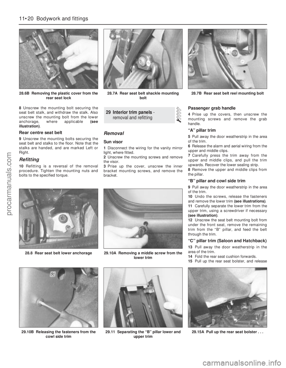
seat belt stalk, and withdraw the stalk. Also
unscrew the mounting bolt from the lower
anchorage, where applicable (see
illustration).
Rear centre seat belt
9Unscrew the mounting bolts securing the
seat belt and stalks to the floor. Note that the
stalks are handed, and are marked Left or
Right.
Refitting
10Refitting is a reversal of the removal
procedure. Tighten the mounting nuts and
bolts to the specified torque.
Removal
Sun visor
1Disconnect the wiring for the vanity mirror
light, where fitted.
2Unscrew the mounting screws and remove
the visor.
3Prise up the cover, unscrew the inner
bracket mounting screws, and remove the
bracket.
Passenger grab handle
4Prise up the covers, then unscrew the
mounting screws and remove the grab
handle.
“A” pillar trim
5Pull away the door weatherstrip in the area
of the trim.
6Release the alarm and aerial wiring from the
upper and middle clips.
7Carefully press the trim away from the
upper and middle clips, and pull the trim
upwards. Recover the lower sealing strip.
8Remove the upper and middle clips from
the pillar.
“B” pillar and cowl side trim
9Pull away the door weatherstrip in the area
of the trim.
10Undo the screws, release the fasteners
and remove the lower trim (see illustrations).
11Carefully separate the lower trim from the
upper trim, using a screwdriver if necessary
(see illustration).
12Unscrew the seat belt mounting bolt from
under the front seat, remove the remaining
trim from the “B” pillar, and feed the belt
through the trim.
“C” pillar trim (Saloon and Hatchback)
13Pull away the door weatherstrip in the
area of the trim.
14Fold the rear seat cushion forwards.
15Pull up the rear seat bolster, and release
29 Interior trim panels-
removal and refitting
11•20 Bodywork and fittings
28.6B Removing the plastic cover from the
rear seat lock28.7A Rear seat belt shackle mounting
bolt28.7B Rear seat belt reel mounting bolt
29.10B Releasing the fasteners from the
cowl side trim29.11 Separating the “B” pillar lower and
upper trim
28.8 Rear seat belt lower anchorage29.10A Removing a middle screw from the
lower trim
29.15A Pull up the rear seat bolster . . .
procarmanuals.com
Page 198 of 279

the upper hook. Note that, on low-series
models, the bolster is retained with a screw
(see illustrations).
16Undo the screw, release the clips, and
detach the upper trim.
17Remove the rear seat belt lower mounting
bolt, then remove the trim, and pass the seat
belt through it.
“C” pillar trim (Estate)
18Prise off the caps, unscrew the screws,
and remove the upper trim from the “C” pillar
(see illustration).
19Unscrew the mounting bolt securing the
rear seat belt upper shackle to the “C” pillar.
20Unclip and remove the trim.
“D” pillar trim (Estate)
21Remove the three mounting screws, then
unclip the trim from the “D” pillar.
Lower facia panel
22Remove the steering column top and
bottom shrouds.
23Unscrew the mounting screws from the
upper corners and above the coin tray
position, and withdraw the lower facia panel
from the facia (see illustrations).
Refitting
24Refitting is a reversal of the removal
procedure. Where seat belt fastenings have
been disturbed, make sure that they are
tightened to the specified torque.
Removal
1Disconnect the battery negative (earth) lead
(Chapter 5, Section 1).
2Pull the ashtray from the facia.
3Pull off the gear lever (or selector lever)
knob (see illustration).
4Using a screwdriver, carefully prise out the
gear lever gaiter/switch panel or selector lever
panel, as applicable. When necessary,
disconnect the wiring multi-plugs (see
illustration).
5Remove the adaptive damping switch,
when fitted (Chapter 12).
30 Centre console-
removal and refitting
Bodywork and fittings 11•21
11
30.4 Prising out the gear lever gaiter30.6A Prise off the plastic caps . . .30.6B . . . and unscrew the mounting
screws at the front top . . .
29.23B . . . and above the coin tray
position . . .
29.23C . . . and withdraw the lower facia
panel30.3 Gear lever knob removal
29.15B . . . and release the upper hook29.18 Screw locations (arrowed) for the
“C” pillar upper trim - Estate models29.23A Unscrew the mounting screws
from the upper corners . . .
procarmanuals.com
Page 264 of 279

Buying spare parts
Spare parts are available from many
sources; for example, Ford garages, other
garages and accessory shops, and motor
factors. Our advice regarding spare part
sources is as follows.
Officially-appointed Ford garages- This is
the best source for parts which are peculiar to
your vehicle, and which are not generally
available (eg complete cylinder heads, internal
transmission components, badges, interior
trim etc). It is also the only place at which you
should buy parts if the vehicle is still under
warranty. To be sure of obtaining the correct
parts, it will be necessary to give the storeman
the full Vehicle Identification Number, and if
possible, to take the old parts along for
positive identification. Many parts are
available under a factory exchange scheme -
any parts returned should always be clean. It
obviously makes good sense to go straight to
the specialists on your vehicle for this type of
part, as they are best equipped to supply you.
Other garages and accessory shops- These
are often very good places to buy materials
and components needed for the maintenance
of your vehicle (eg oil filters, spark plugs,
bulbs, drivebelts, oils and greases, touch-up
paint, filler paste, etc). They also sell general
accessories, usually have convenient opening
hours, charge lower prices, and can often be
found not far from home.
Motor factors- Good factors will stock all
the more important components which wear
out comparatively quickly (eg exhaust
systems, brake pads, seals and hydraulic
parts, clutch components, bearing shells,
pistons, valves etc). Motor factors will often
provide new or reconditioned components on
a part-exchange basis - this can save a
considerable amount of money.
Vehicle identification numbers
Modifications are a continuing and
unpublicised process in vehicle manufacture,
quite apart from major model changes. Spare
parts manuals and lists are compiled upon a
numerical basis, the appropriate identification
number or code being essential to correct
identification of the component concerned.
When ordering spare parts, always give asmuch information as possible. Quote the
vehicle model, year of manufacture, Vehicle
Identification Number and engine numbers, as
appropriate.
The vehicle identification plateis located on
the engine compartment front crossmember
(see illustration). In addition to many other
details, it carries the Vehicle Identification
Number, maximum vehicle weight
information, and codes for interior trim and
body colours.
The Vehicle Identification Numberis given
on the vehicle identification plate. It is also
stamped on the engine compartment
bulkhead, behind the air intake plenum
chamber, and into the body, so that it can be
seen through the bottom left-hand corner of
the windscreen (see illustrations).The engine number, consisting of two
letters and five digits, with the three-letter
engine code nearby, is stamped into a flat-
machined surface on the cylinder
block/crankcase’s forward-facing flange,
between the pulse-air filter housing and the
transmission. To read the number without
removing the engine compartment air intake
resonator - see Chapter 4 - it is easiest to
raise and support the front of the vehicle on
axle stands, so that the number can be seen
from underneath (see illustration). If the
number cannot be seen in this location,
possible alternative sites are on a lower flange
on the cylinder block’s forward face,
immediately above the sump mating surface,
or on the left-hand end of the cylinder head,
between the oil filler cap and ignition coil.
REF•5
Vehicle identification plate on engine
compartment front crossmember
Vehicle identification number in body,
visible through bottom left-hand corner of
windscreen
Vehicle identification number on engine
compartment bulkhead
Engine number (arrowed) on front of
cylinder block/crankcase - seen from
beneath vehicle
Spare Parts/Vehicle Identification
procarmanuals.com