oil dipstick FORD MONDEO 1993 Service Repair Manual
[x] Cancel search | Manufacturer: FORD, Model Year: 1993, Model line: MONDEO, Model: FORD MONDEO 1993Pages: 279, PDF Size: 12.71 MB
Page 16 of 279
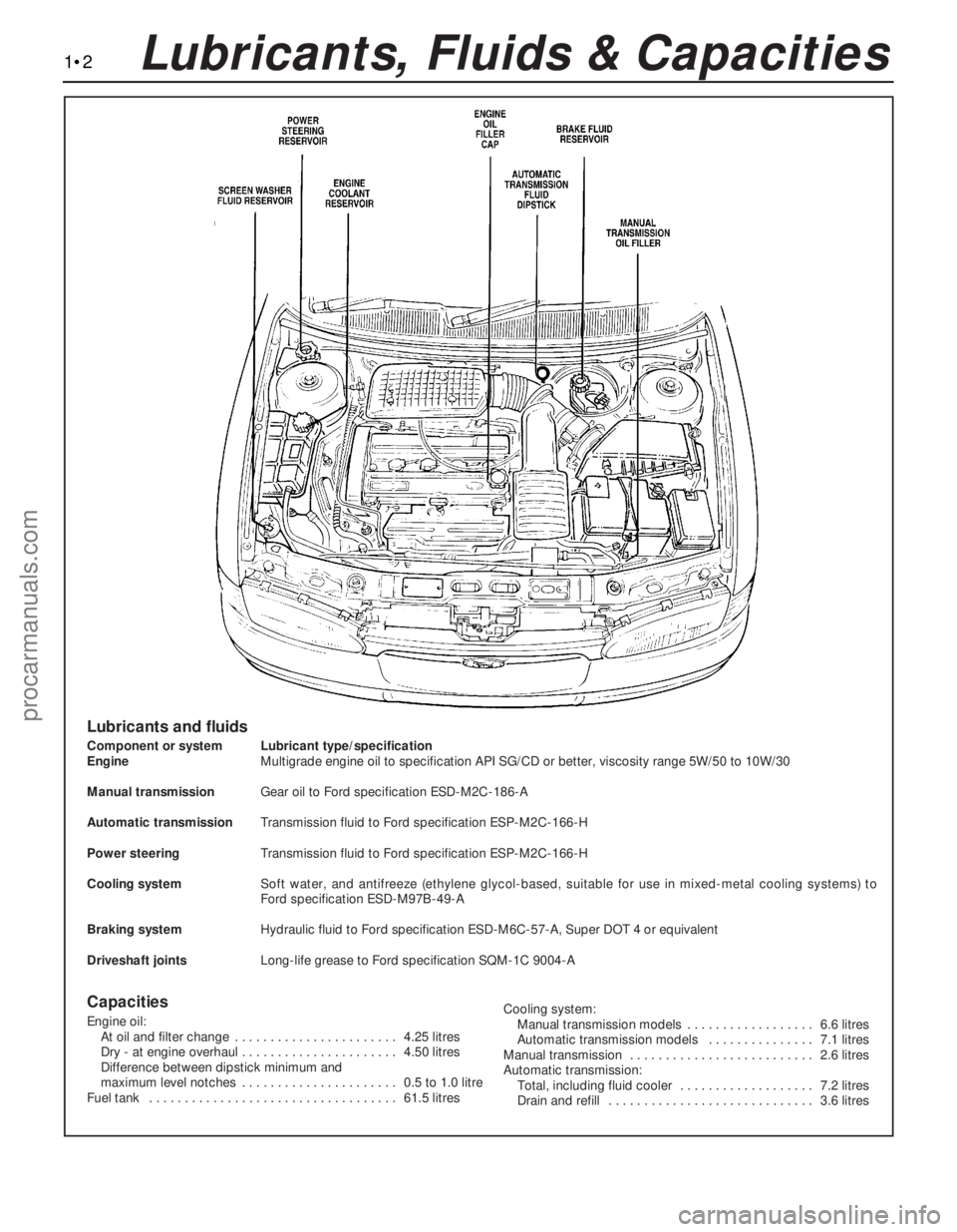
1•2Lubricants, Fluids & Capacities
Lubricants and fluids
Component or system Lubricant type/specification
EngineMultigrade engine oil to specification API SG/CD or better, viscosity range 5W/50 to 10W/30
Manual transmissionGear oil to Ford specification ESD-M2C-186-A
Automatic transmissionTransmission fluid to Ford specification ESP-M2C-166-H
Power steeringTransmission fluid to Ford specification ESP-M2C-166-H
Cooling systemSoft water, and antifreeze (ethylene glycol-based, suitable for use in mixed-metal cooling systems) to
Ford specification ESD-M97B-49-A
Braking systemHydraulic fluid to Ford specification ESD-M6C-57-A, Super DOT 4 or equivalent
Driveshaft jointsLong-life grease to Ford specification SQM-1C 9004-A
Capacities
Engine oil:
At oil and filter change . . . . . . . . . . . . . . . . . . . . . . . 4.25 litres
Dry - at engine overhaul . . . . . . . . . . . . . . . . . . . . . . 4.50 litres
Difference between dipstick minimum and
maximum level notches . . . . . . . . . . . . . . . . . . . . . . 0.5 to 1.0 litre
Fuel tank . . . . . . . . . . . . . . . . . . . . . . . . . . . . . . . . . . . 61.5 litresCooling system:
Manual transmission models . . . . . . . . . . . . . . . . . . 6.6 litres
Automatic transmission models . . . . . . . . . . . . . . . 7.1 litres
Manual transmission . . . . . . . . . . . . . . . . . . . . . . . . . . 2.6 litres
Automatic transmission:
Total, including fluid cooler . . . . . . . . . . . . . . . . . . . 7.2 litres
Drain and refill . . . . . . . . . . . . . . . . . . . . . . . . . . . . . 3.6 litres
procarmanuals.com
Page 18 of 279
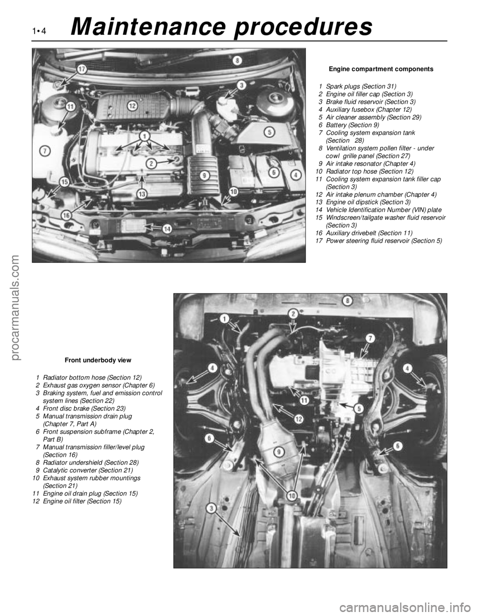
1•4
Engine compartment components
1 Spark plugs (Section 31)
2 Engine oil filler cap (Section 3)
3 Brake fluid reservoir (Section 3)
4 Auxiliary fusebox (Chapter 12)
5 Air cleaner assembly (Section 29)
6 Battery (Section 9)
7 Cooling system expansion tank
(Section 28)
8 Ventilation system pollen filter - under
cowl grille panel (Section 27)
9 Air intake resonator (Chapter 4)
10 Radiator top hose (Section 12)
11 Cooling system expansion tank filler cap
(Section 3)
12 Air intake plenum chamber (Chapter 4)
13 Engine oil dipstick (Section 3)
14 Vehicle Identification Number (VIN) plate
15 Windscreen/tailgate washer fluid reservoir
(Section 3)
16 Auxiliary drivebelt (Section 11)
17 Power steering fluid reservoir (Section 5)
Front underbody view
1 Radiator bottom hose (Section 12)
2 Exhaust gas oxygen sensor (Chapter 6)
3 Braking system, fuel and emission control
system lines (Section 22)
4 Front disc brake (Section 23)
5 Manual transmission drain plug
(Chapter 7, Part A)
6 Front suspension subframe (Chapter 2,
Part B)
7 Manual transmission filler/level plug
(Section 16)
8 Radiator undershield (Section 28)
9 Catalytic converter (Section 21)
10 Exhaust system rubber mountings
(Section 21)
11 Engine oil drain plug (Section 15)
12 Engine oil filter (Section 15)
Maintenance procedures
procarmanuals.com
Page 20 of 279
This Chapter is designed to help the home
mechanic maintain the Ford Mondeo models
for peak performance, economy, safety and
long life.
On the following pages are Sections
dealing specifically with each item on the
maintenance schedule. Visual checks,
adjustments, component replacement and
other helpful items are included. Refer to the
accompanying illustrations of the engine
compartment and the underside of the vehicle
for the location of various components.
Servicing your Mondeo in accordance with
the mileage/time maintenance schedule and
the following Sections will provide it with a
planned maintenance programme, which
should result in a long and reliable service life.
This is a comprehensive plan, so maintaining
some items but not others at the specified
service intervals will not produce the same
results.
As you service your Mondeo, you will
discover that many of the procedures can -
and should - be grouped together, because of
the nature of the particular procedure you’re
performing, or because of the close proximity
to one another of two otherwise-unrelated
components.
For example, if the vehicle is raised for anyreason, you should inspect the exhaust,
suspension, steering and fuel systems while
you’re under the vehicle. When you’re
checking the tyres, it makes good sense to
check the brakes and wheel bearings,
especially if the roadwheels have already
been removed.
Finally, let’s suppose you have to borrow or
hire a torque wrench. Even if you only need to
tighten the spark plugs, you might as well
check the torque of as many critical fasteners
as time allows.
The first step of this maintenance
programme is to prepare yourself before the
actual work begins. Read through all the
Sections which are relevant to the procedures
you’re planning to carry out, then make a list
of, and gather together, all the parts and tools
you will need to do the job. If it looks as if you
might run into problems during a particular
segment of some procedure, seek advice
from your local parts man or dealer service
department.
Ford state that, where antifreeze to
specification ESD-M97B-49-A (the type with
which the vehicle’s cooling system would
have been filled on production at the factory)
is used, it will last the lifetime of the vehicle.This is subject to it being used in the
recommended concentration, unmixed with
any other type of antifreeze or additive, and
topped-up when necessary using only that
antifreeze mixed 50/50 with clean water. If any
other type of antifreeze is added, the lifetime
guarantee no longer applies; to restore the
lifetime protection, the system must be
drained and thoroughly reverse-flushed
before fresh coolant mixture is poured in.
If the vehicle’s history (and therefore the
quality of the antifreeze in it) is unknown,
owners who wish to follow Ford’s
recommendations are advised to drain and
thoroughly reverse-flush the system, as
outlined in Section 28, before refilling with
fresh coolant mixture. If the appropriate
quality of antifreeze is used, the coolant can
then be left for the life of the vehicle.
If any antifreeze other than Ford’s is to be
used, the coolant must be renewed at regular
intervals to provide an equivalent degree of
protection; the conventional recommendation
is to renew the coolant every two years.
The above assumes the use of a mixture (in
exactly the specified concentration) of clean,
soft water and of antifreeze to Ford’s
specification or equivalent. It is also assumed
that the cooling system is maintained in a
scrupulously-clean condition, by ensuring that
only clean coolant is added on topping-up,
and by thorough reverse-flushing whenever
the coolant is drained (Section 28).
2 Coolant renewal
1 Introduction
1•6Weekly checks
Weekly checks
General
1Fluids are an essential part of the
lubrication, cooling, braking and other
systems. Because these fluids gradually
become depleted and/or contaminated during
normal operation of the vehicle, they must be
periodically replenished. See “Lubricants and
fluids and capacities”at the beginning of this
Chapter before adding fluid to any of the
following components. Note:The vehicle
must be on level ground before fluid levels can
be checked.
Engine oil
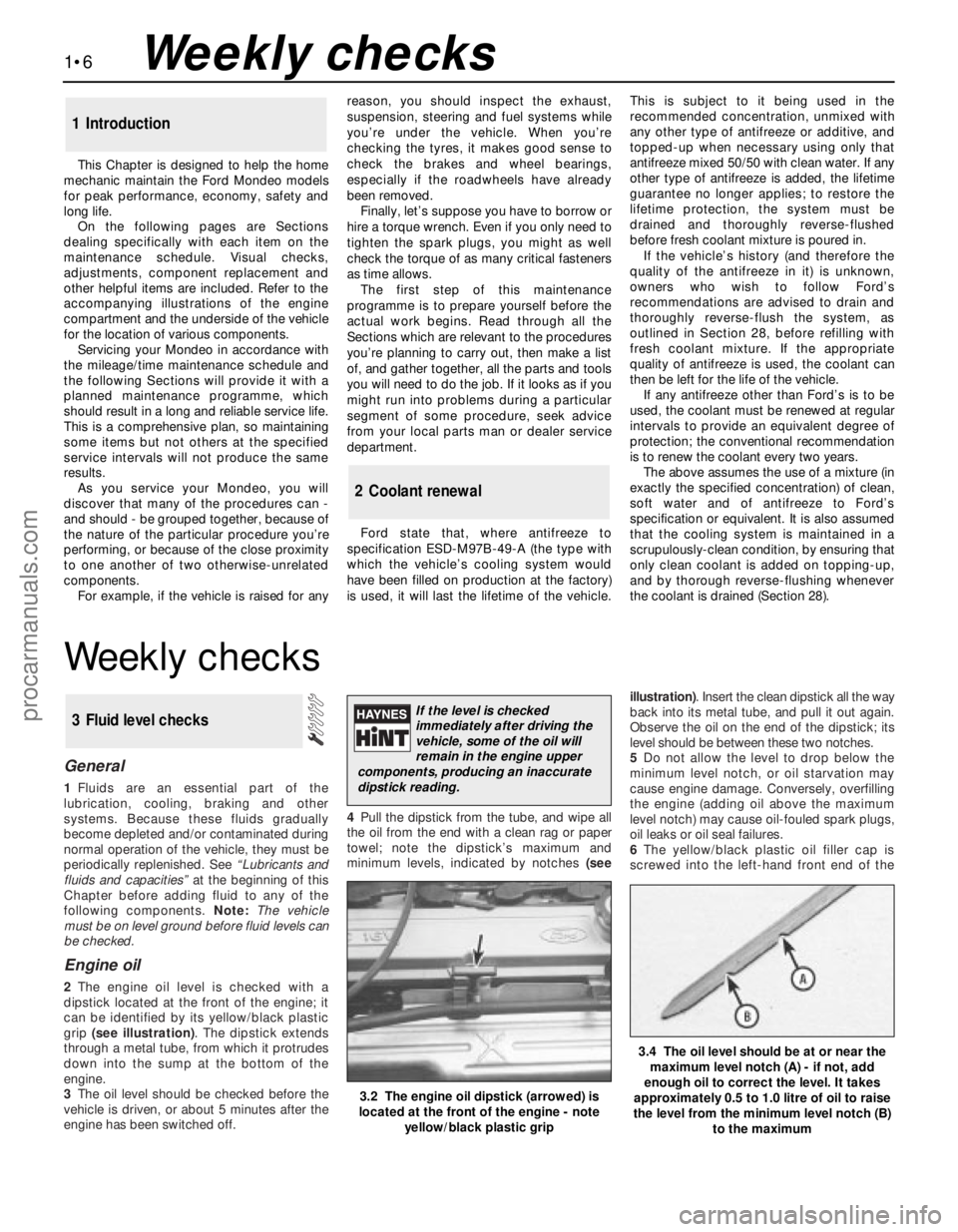
2The engine oil level is checked with a
dipstick located at the front of the engine; it
can be identified by its yellow/black plastic
grip (see illustration). The dipstick extends
through a metal tube, from which it protrudes
down into the sump at the bottom of the
engine.
3The oil level should be checked before the
vehicle is driven, or about 5 minutes after the
engine has been switched off.4Pull the dipstick from the tube, and wipe all
the oil from the end with a clean rag or paper
towel; note the dipstick’s maximum and
minimum levels, indicated by notches (seeillustration). Insert the clean dipstick all the way
back into its metal tube, and pull it out again.
Observe the oil on the end of the dipstick; its
level should be between these two notches.
5Do not allow the level to drop below the
minimum level notch, or oil starvation may
cause engine damage. Conversely, overfilling
the engine (adding oil above the maximum
level notch) may cause oil-fouled spark plugs,
oil leaks or oil seal failures.
6The yellow/black plastic oil filler cap is
screwed into the left-hand front end of the
3 Fluid level checks
3.2 The engine oil dipstick (arrowed) is
located at the front of the engine - note
yellow/black plastic grip
3.4 The oil level should be at or near the
maximum level notch (A) - if not, add
enough oil to correct the level. It takes
approximately 0.5 to 1.0 litre of oil to raise
the level from the minimum level notch (B)
to the maximum
If the level is checked
immediately after driving the
vehicle, some of the oil will
remain in the engine upper
components, producing an inaccurate
dipstick reading.
procarmanuals.com
Page 21 of 279
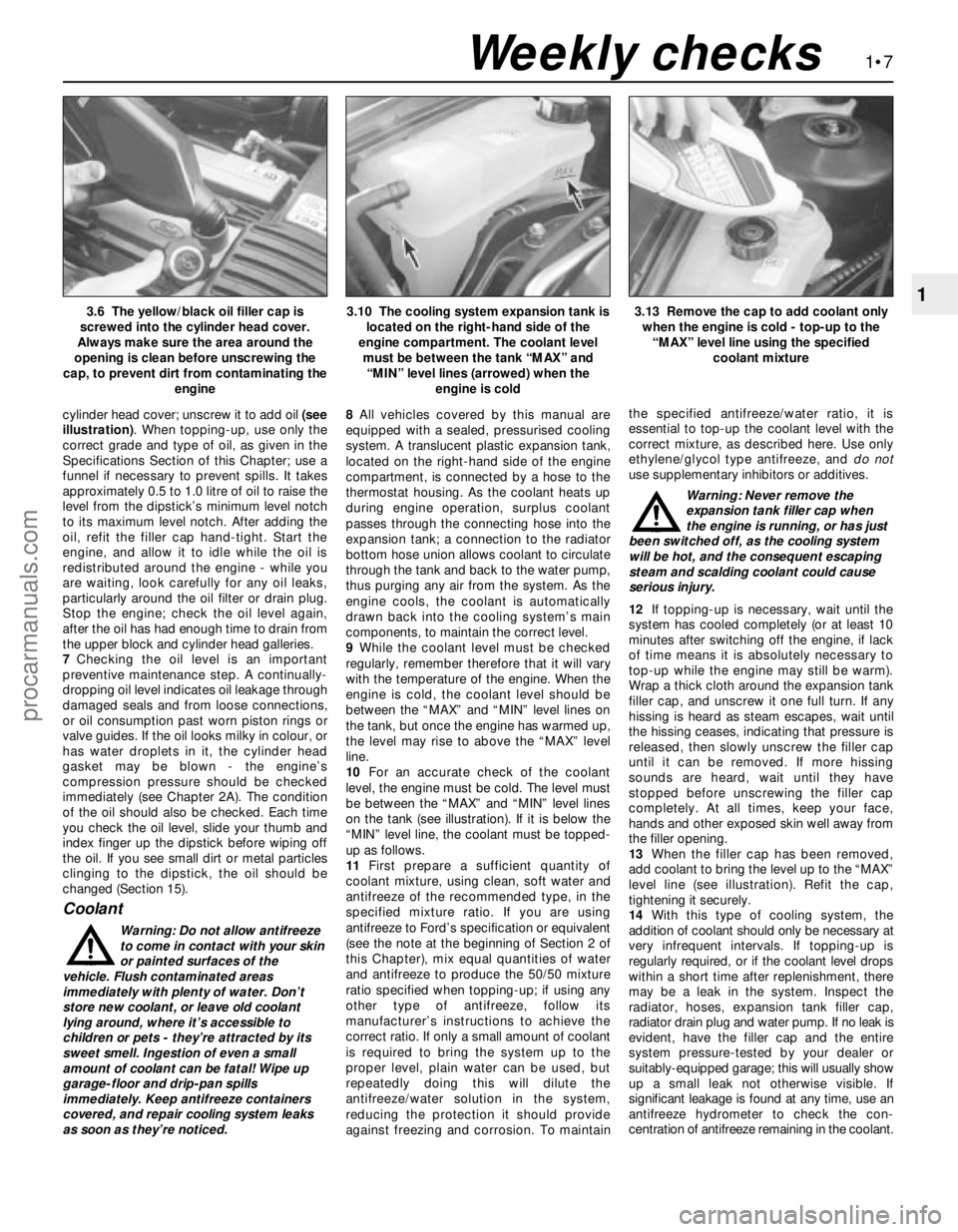
cylinder head cover; unscrew it to add oil (see
illustration). When topping-up, use only the
correct grade and type of oil, as given in the
Specifications Section of this Chapter; use a
funnel if necessary to prevent spills. It takes
approximately 0.5 to 1.0 litre of oil to raise the
level from the dipstick’s minimum level notch
to its maximum level notch. After adding the
oil, refit the filler cap hand-tight. Start the
engine, and allow it to idle while the oil is
redistributed around the engine - while you
are waiting, look carefully for any oil leaks,
particularly around the oil filter or drain plug.
Stop the engine; check the oil level again,
after the oil has had enough time to drain from
the upper block and cylinder head galleries.
7Checking the oil level is an important
preventive maintenance step. A continually-
dropping oil level indicates oil leakage through
damaged seals and from loose connections,
or oil consumption past worn piston rings or
valve guides. If the oil looks milky in colour, or
has water droplets in it, the cylinder head
gasket may be blown - the engine’s
compression pressure should be checked
immediately (see Chapter 2A). The condition
of the oil should also be checked. Each time
you check the oil level, slide your thumb and
index finger up the dipstick before wiping off
the oil. If you see small dirt or metal particles
clinging to the dipstick, the oil should be
changed (Section 15).
Coolant
Warning: Do not allow antifreeze
to come in contact with your skin
or painted surfaces of the
vehicle. Flush contaminated areas
immediately with plenty of water. Don’t
store new coolant, or leave old coolant
lying around, where it’s accessible to
children or pets - they’re attracted by its
sweet smell. Ingestion of even a small
amount of coolant can be fatal! Wipe up
garage-floor and drip-pan spills
immediately. Keep antifreeze containers
covered, and repair cooling system leaks
as soon as they’re noticed.8All vehicles covered by this manual are
equipped with a sealed, pressurised cooling
system. A translucent plastic expansion tank,
located on the right-hand side of the engine
compartment, is connected by a hose to the
thermostat housing. As the coolant heats up
during engine operation, surplus coolant
passes through the connecting hose into the
expansion tank; a connection to the radiator
bottom hose union allows coolant to circulate
through the tank and back to the water pump,
thus purging any air from the system. As the
engine cools, the coolant is automatically
drawn back into the cooling system’s main
components, to maintain the correct level.
9While the coolant level must be checked
regularly, remember therefore that it will vary
with the temperature of the engine. When the
engine is cold, the coolant level should be
between the “MAX” and “MIN” level lines on
the tank, but once the engine has warmed up,
the level may rise to above the “MAX” level
line.
10For an accurate check of the coolant
level, the engine must be cold. The level must
be between the “MAX” and “MIN” level lines
on the tank (see illustration). If it is below the
“MIN” level line, the coolant must be topped-
up as follows.
11First prepare a sufficient quantity of
coolant mixture, using clean, soft water and
antifreeze of the recommended type, in the
specified mixture ratio. If you are using
antifreeze to Ford’s specification or equivalent
(see the note at the beginning of Section 2 of
this Chapter), mix equal quantities of water
and antifreeze to produce the 50/50 mixture
ratio specified when topping-up; if using any
other type of antifreeze, follow its
manufacturer’s instructions to achieve the
correct ratio. If only a small amount of coolant
is required to bring the system up to the
proper level, plain water can be used, but
repeatedly doing this will dilute the
antifreeze/water solution in the system,
reducing the protection it should provide
against freezing and corrosion. To maintainthe specified antifreeze/water ratio, it is
essential to top-up the coolant level with the
correct mixture, as described here. Use only
ethylene/glycol type antifreeze, and do not
use supplementary inhibitors or additives.
Warning: Never remove the
expansion tank filler cap when
the engine is running, or has just
been switched off, as the cooling system
will be hot, and the consequent escaping
steam and scalding coolant could cause
serious injury.
12If topping-up is necessary, wait until the
system has cooled completely (or at least 10
minutes after switching off the engine, if lack
of time means it is absolutely necessary to
top-up while the engine may still be warm).
Wrap a thick cloth around the expansion tank
filler cap, and unscrew it one full turn. If any
hissing is heard as steam escapes, wait until
the hissing ceases, indicating that pressure is
released, then slowly unscrew the filler cap
until it can be removed. If more hissing
sounds are heard, wait until they have
stopped before unscrewing the filler cap
completely. At all times, keep your face,
hands and other exposed skin well away from
the filler opening.
13When the filler cap has been removed,
add coolant to bring the level up to the “MAX”
level line (see illustration). Refit the cap,
tightening it securely.
14With this type of cooling system, the
addition of coolant should only be necessary at
very infrequent intervals. If topping-up is
regularly required, or if the coolant level drops
within a short time after replenishment, there
may be a leak in the system. Inspect the
radiator, hoses, expansion tank filler cap,
radiator drain plug and water pump. If no leak is
evident, have the filler cap and the entire
system pressure-tested by your dealer or
suitably-equipped garage; this will usually show
up a small leak not otherwise visible. If
significant leakage is found at any time, use an
antifreeze hydrometer to check the con-
centration of antifreeze remaining in the coolant.
1•7
13.13 Remove the cap to add coolant only
when the engine is cold - top-up to the
“MAX” level line using the specified
coolant mixture3.6 The yellow/black oil filler cap is
screwed into the cylinder head cover.
Always make sure the area around the
opening is clean before unscrewing the
cap, to prevent dirt from contaminating the
engine3.10 The cooling system expansion tank is
located on the right-hand side of the
engine compartment. The coolant level
must be between the tank “MAX” and
“MIN” level lines (arrowed) when the
engine is cold
Weekly checks
procarmanuals.com
Page 30 of 279
comb” or compressed air to clean the
condenser.
Warning: Wear eye protection
when using compressed air!
(d) Check that the drain tube from the front
of the evaporator is clear - note that it is
normal to have clear fluid (water) dripping
from this while the system is in operation,
to the extent that quite a large puddle can
be left under the vehicle when it is parked.
2It’s a good idea to operate the system forabout 30 minutes at least once a month,
particularly during the winter. Long term
non-use can cause hardening, and
subsequent failure, of the seals.
3Because of the complexity of the air
conditioning system and the special
equipment necessary to service it, in-depth
fault diagnosis and repairs are not included in
this manual. For more complete information
on the air conditioning system, refer to the
Haynes Automotive Heating and Air
Conditioning Manual.
4The most common cause of poor cooling is
simply a low system refrigerant charge. If a
noticeable drop in cool air output occurs, the
following quick check will help you determine
if the refrigerant level is low.
5Warm the engine up to normal operating
temperature.
6Place the air conditioning temperature
selector at the coldest setting, and put the
blower at the highest setting. Open the doors
- to make sure the air conditioning system
doesn’t cycle off as soon as it cools the
passenger compartment.
7With the compressor engaged - the clutch
will make an audible click, and the centre of
the clutch will rotate - feel the inlet and outlet
pipes at the compressor. One side should be
cold, and one hot. If there’s no perceptible
difference between the two pipes, there’s
something wrong with the compressor or the
system. It might be a low charge - it might be
something else. Take the vehicle to a dealer
service department or an automotive air
conditioning specialist.1Make sure that you have all the necessary
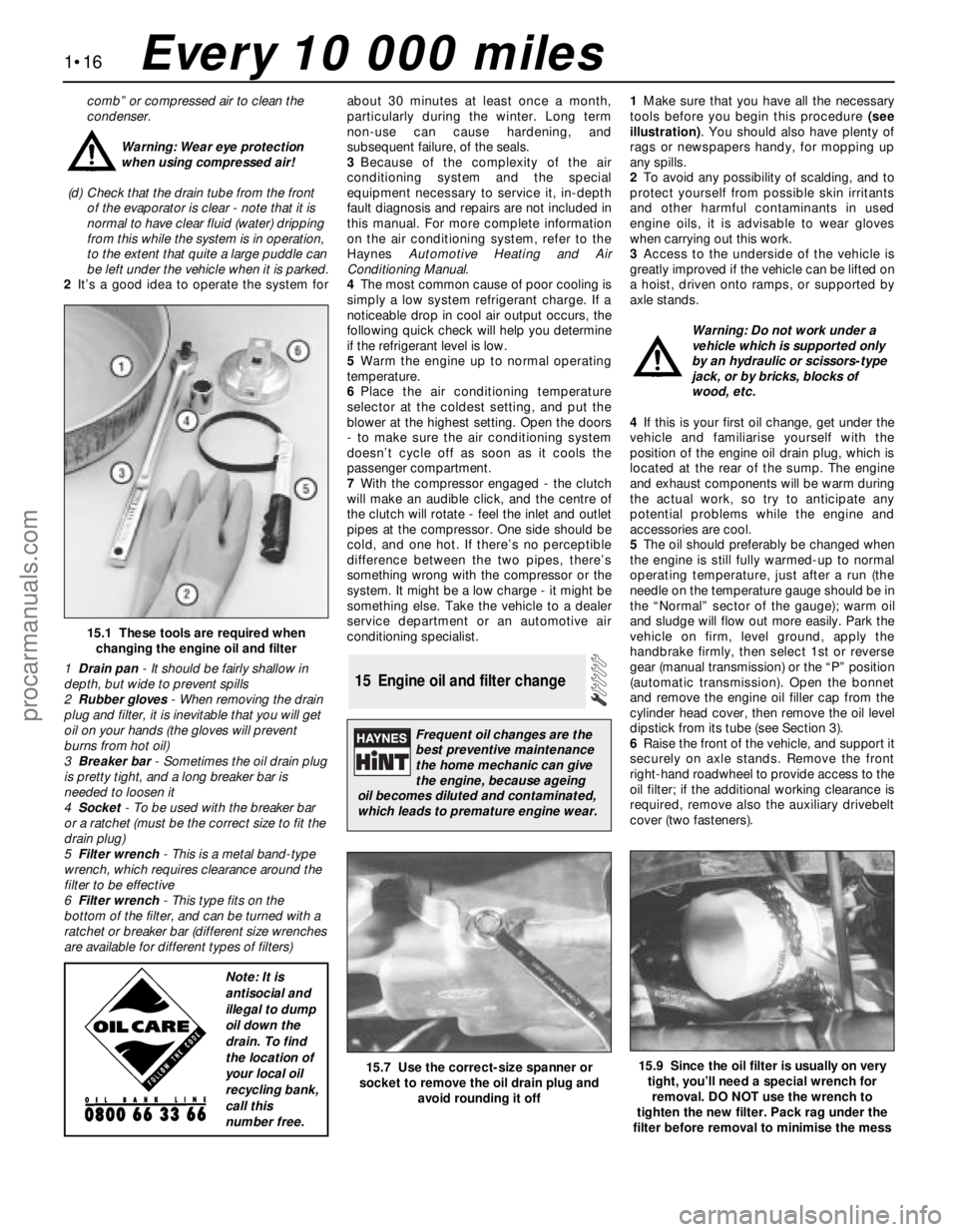
tools before you begin this procedure (see
illustration). You should also have plenty of
rags or newspapers handy, for mopping up
any spills.
2To avoid any possibility of scalding, and to
protect yourself from possible skin irritants
and other harmful contaminants in used
engine oils, it is advisable to wear gloves
when carrying out this work.
3Access to the underside of the vehicle is
greatly improved if the vehicle can be lifted on
a hoist, driven onto ramps, or supported by
axle stands.
Warning: Do not work under a
vehicle which is supported only
by an hydraulic or scissors-type
jack, or by bricks, blocks of
wood, etc.
4If this is your first oil change, get under the
vehicle and familiarise yourself with the
position of the engine oil drain plug, which is
located at the rear of the sump. The engine
and exhaust components will be warm during
the actual work, so try to anticipate any
potential problems while the engine and
accessories are cool.
5The oil should preferably be changed when
the engine is still fully warmed-up to normal
operating temperature, just after a run (the
needle on the temperature gauge should be in
the “Normal” sector of the gauge); warm oil
and sludge will flow out more easily. Park the
vehicle on firm, level ground, apply the
handbrake firmly, then select 1st or reverse
gear (manual transmission) or the “P” position
(automatic transmission). Open the bonnet
and remove the engine oil filler cap from the
cylinder head cover, then remove the oil level
dipstick from its tube (see Section 3).
6Raise the front of the vehicle, and support it
securely on axle stands. Remove the front
right-hand roadwheel to provide access to the
oil filter; if the additional working clearance is
required, remove also the auxiliary drivebelt
cover (two fasteners).
15 Engine oil and filter change
1•16
15.1 These tools are required when
changing the engine oil and filter
1Drain pan- It should be fairly shallow in
depth, but wide to prevent spills
2Rubber gloves- When removing the drain
plug and filter, it is inevitable that you will get
oil on your hands (the gloves will prevent
burns from hot oil)
3Breaker bar- Sometimes the oil drain plug
is pretty tight, and a long breaker bar is
needed to loosen it
4Socket- To be used with the breaker bar
or a ratchet (must be the correct size to fit the
drain plug)
5Filter wrench- This is a metal band-type
wrench, which requires clearance around the
filter to be effective
6Filter wrench- This type fits on the
bottom of the filter, and can be turned with a
ratchet or breaker bar (different size wrenches
are available for different types of filters)
15.7 Use the correct-size spanner or
socket to remove the oil drain plug and
avoid rounding it off15.9 Since the oil filter is usually on very
tight, you’ll need a special wrench for
removal. DO NOT use the wrench to
tighten the new filter. Pack rag under the
filter before removal to minimise the mess
Every 10 000 miles
Frequent oil changes are the
best preventive maintenance
the home mechanic can give
the engine, because ageing
oil becomes diluted and contaminated,
which leads to premature engine wear.
Note: It is
antisocial and
illegal to dump
oil down the
drain. To find
the location of
your local oil
recycling bank,
call this
number free.
procarmanuals.com
Page 31 of 279
Warning: To avoid personal
injury, never get beneath the
vehicle when it is supported by
only by a jack. The jack provided
with your vehicle is designed solely for
raising the vehicle to remove and refit the
roadwheels. Always use axle stands to
support the vehicle when it becomes
necessary to place your body underneath
the vehicle.
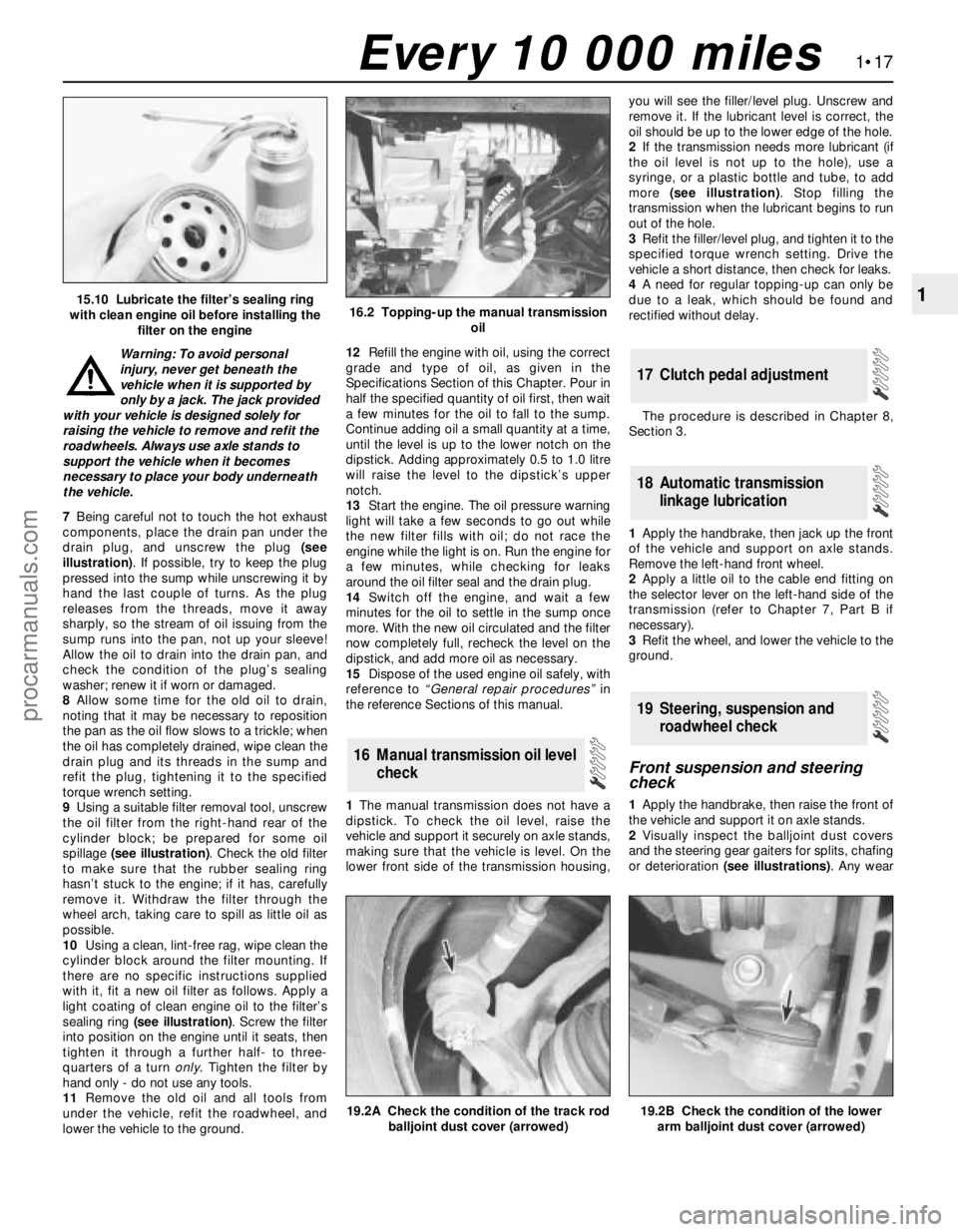
7Being careful not to touch the hot exhaust
components, place the drain pan under the
drain plug, and unscrew the plug (see
illustration). If possible, try to keep the plug
pressed into the sump while unscrewing it by
hand the last couple of turns. As the plug
releases from the threads, move it away
sharply, so the stream of oil issuing from the
sump runs into the pan, not up your sleeve!
Allow the oil to drain into the drain pan, and
check the condition of the plug’s sealing
washer; renew it if worn or damaged.
8Allow some time for the old oil to drain,
noting that it may be necessary to reposition
the pan as the oil flow slows to a trickle; when
the oil has completely drained, wipe clean the
drain plug and its threads in the sump and
refit the plug, tightening it to the specified
torque wrench setting.
9Using a suitable filter removal tool, unscrew
the oil filter from the right-hand rear of the
cylinder block; be prepared for some oil
spillage (see illustration). Check the old filter
to make sure that the rubber sealing ring
hasn’t stuck to the engine; if it has, carefully
remove it. Withdraw the filter through the
wheel arch, taking care to spill as little oil as
possible.
10Using a clean, lint-free rag, wipe clean the
cylinder block around the filter mounting. If
there are no specific instructions supplied
with it, fit a new oil filter as follows. Apply a
light coating of clean engine oil to the filter’s
sealing ring (see illustration). Screw the filter
into position on the engine until it seats, then
tighten it through a further half- to three-
quarters of a turn only. Tighten the filter by
hand only - do not use any tools.
11Remove the old oil and all tools from
under the vehicle, refit the roadwheel, and
lower the vehicle to the ground.12Refill the engine with oil, using the correct
grade and type of oil, as given in the
Specifications Section of this Chapter. Pour in
half the specified quantity of oil first, then wait
a few minutes for the oil to fall to the sump.
Continue adding oil a small quantity at a time,
until the level is up to the lower notch on the
dipstick. Adding approximately 0.5 to 1.0 litre
will raise the level to the dipstick’s upper
notch.
13Start the engine. The oil pressure warning
light will take a few seconds to go out while
the new filter fills with oil; do not race the
engine while the light is on. Run the engine for
a few minutes, while checking for leaks
around the oil filter seal and the drain plug.
14Switch off the engine, and wait a few
minutes for the oil to settle in the sump once
more. With the new oil circulated and the filter
now completely full, recheck the level on the
dipstick, and add more oil as necessary.
15Dispose of the used engine oil safely, with
reference to “General repair procedures”in
the reference Sections of this manual.
1The manual transmission does not have a
dipstick. To check the oil level, raise the
vehicle and support it securely on axle stands,
making sure that the vehicle is level. On the
lower front side of the transmission housing,you will see the filler/level plug. Unscrew and
remove it. If the lubricant level is correct, the
oil should be up to the lower edge of the hole.
2If the transmission needs more lubricant (if
the oil level is not up to the hole), use a
syringe, or a plastic bottle and tube, to add
more (see illustration). Stop filling the
transmission when the lubricant begins to run
out of the hole.
3Refit the filler/level plug, and tighten it to the
specified torque wrench setting. Drive the
vehicle a short distance, then check for leaks.
4A need for regular topping-up can only be
due to a leak, which should be found and
rectified without delay.
The procedure is described in Chapter 8,
Section 3.
1Apply the handbrake, then jack up the front
of the vehicle and support on axle stands.
Remove the left-hand front wheel.
2Apply a little oil to the cable end fitting on
the selector lever on the left-hand side of the
transmission (refer to Chapter 7, Part B if
necessary).
3Refit the wheel, and lower the vehicle to the
ground.
Front suspension and steering
check
1Apply the handbrake, then raise the front of
the vehicle and support it on axle stands.
2Visually inspect the balljoint dust covers
and the steering gear gaiters for splits, chafing
or deterioration (see illustrations). Any wear
19 Steering, suspension and
roadwheel check
18 Automatic transmission
linkage lubrication
17 Clutch pedal adjustment
16 Manual transmission oil level
check
1•17
1
19.2B Check the condition of the lower
arm balljoint dust cover (arrowed)
15.10 Lubricate the filter’s sealing ring
with clean engine oil before installing the
filter on the engine16.2 Topping-up the manual transmission
oil
19.2A Check the condition of the track rod
balljoint dust cover (arrowed)
Every 10 000 miles
procarmanuals.com
Page 42 of 279

Lubrication
Engine oil type/specification . . . . . . . . . . . . . . . . . . . . . . . . . . . . . . . . . . See Chapter 1
Engine oil capacity . . . . . . . . . . . . . . . . . . . . . . . . . . . . . . . . . . . . . . . . . See Chapter 1
Oil pressure . . . . . . . . . . . . . . . . . . . . . . . . . . . . . . . . . . . . . . . . . . . . . . . No information available at time of writing
Oil pump clearances . . . . . . . . . . . . . . . . . . . . . . . . . . . . . . . . . . . . . . . . No information available at time of writing
Torque wrench settingsNm lbf ft
Cylinder head cover bolts:
Stage 1 . . . . . . . . . . . . . . . . . . . . . . . . . . . . . . . . . . . . . . . . . . . . . . . . 2 1.5
Stage 2 . . . . . . . . . . . . . . . . . . . . . . . . . . . . . . . . . . . . . . . . . . . . . . . . 7 5
Camshaft toothed pulley bolts . . . . . . . . . . . . . . . . . . . . . . . . . . . . . . . . 68 50
Camshaft bearing cap bolts:
Stage 1 . . . . . . . . . . . . . . . . . . . . . . . . . . . . . . . . . . . . . . . . . . . . . . . . 10 7
Stage 2 . . . . . . . . . . . . . . . . . . . . . . . . . . . . . . . . . . . . . . . . . . . . . . . . 19 14
Cylinder head bolts:
Stage 1 . . . . . . . . . . . . . . . . . . . . . . . . . . . . . . . . . . . . . . . . . . . . . . . . 25 18
Stage 2 . . . . . . . . . . . . . . . . . . . . . . . . . . . . . . . . . . . . . . . . . . . . . . . . 45 33
Stage 3 . . . . . . . . . . . . . . . . . . . . . . . . . . . . . . . . . . . . . . . . . . . . . . . . Angle-tighten a further 105°
Timing belt cover fasteners:
Upper-to-middle (outer) cover bolts . . . . . . . . . . . . . . . . . . . . . . . . . . 4 3
Cover-to-cylinder head or block bolts . . . . . . . . . . . . . . . . . . . . . . . . 7 5
Cover studs-to-cylinder head or block . . . . . . . . . . . . . . . . . . . . . . . . 9 to 11 6.5 to 8
Timing belt tensioner bolt . . . . . . . . . . . . . . . . . . . . . . . . . . . . . . . . . . . . 38 28
Timing belt tensioner backplate locating peg . . . . . . . . . . . . . . . . . . . . . 8 to 11 6 to 8
Timing belt tensioner spring retaining pin . . . . . . . . . . . . . . . . . . . . . . . . 10 7
Timing belt guide pulley bolts . . . . . . . . . . . . . . . . . . . . . . . . . . . . . . . . . 35 to 40 26 to 30
Water pump pulley bolts . . . . . . . . . . . . . . . . . . . . . . . . . . . . . . . . . . . . . 10 7
Water pump bolts . . . . . . . . . . . . . . . . . . . . . . . . . . . . . . . . . . . . . . . . . . See Chapter 3
Auxiliary drivebelt idler pulley . . . . . . . . . . . . . . . . . . . . . . . . . . . . . . . . . 48 35
Inlet manifold nuts and bolts . . . . . . . . . . . . . . . . . . . . . . . . . . . . . . . . . . 18 13
Alternator mounting bracket-to-cylinder block bolts . . . . . . . . . . . . . . . 47 35
Cylinder head support plates:
Front plate Torx screws - to power steering pump/air conditioning
compressor mounting bracket and cylinder head . . . . . . . . . . . . . . . 47 35
Rear plate/engine lifting eye - to alternator mounting bracket
and cylinder head bolts . . . . . . . . . . . . . . . . . . . . . . . . . . . . . . . . . . . . 47 35
Front engine lifting eye bolt . . . . . . . . . . . . . . . . . . . . . . . . . . . . . . . . . . . 16 12
Inlet and exhaust manifold studs-to-cylinder head . . . . . . . . . . . . . . . . 10 maximum 7 maximum
Exhaust manifold heat shield bolts:
Shield-to-cylinder head . . . . . . . . . . . . . . . . . . . . . . . . . . . . . . . . . . . . 7 5
Shield/dipstick tube . . . . . . . . . . . . . . . . . . . . . . . . . . . . . . . . . . . . . . . 10 7
Shield/coolant pipe-to-manifold . . . . . . . . . . . . . . . . . . . . . . . . . . . . . 23 17
Exhaust manifold nuts . . . . . . . . . . . . . . . . . . . . . . . . . . . . . . . . . . . . . . . 16 12
Air conditioning refrigerant pipe-to-exhaust manifold bolts . . . . . . . . . . 10 7
Crankshaft pulley bolt . . . . . . . . . . . . . . . . . . . . . . . . . . . . . . . . . . . . . . . 108 to 115 80 to 85
Oil pump-to-cylinder block bolts . . . . . . . . . . . . . . . . . . . . . . . . . . . . . . 10 7
Oil pick-up pipe-to-pump screws . . . . . . . . . . . . . . . . . . . . . . . . . . . . . . 10 7
Oil baffle/pump pick-up pipe nuts . . . . . . . . . . . . . . . . . . . . . . . . . . . . . 19 14
Oil filter adaptor-to-pump . . . . . . . . . . . . . . . . . . . . . . . . . . . . . . . . . . . . 18 to 25 13 to 18
Oil pressure warning light switch . . . . . . . . . . . . . . . . . . . . . . . . . . . . . . 27 20
Oil level sensor . . . . . . . . . . . . . . . . . . . . . . . . . . . . . . . . . . . . . . . . . . . . 27 20
Sump bolts . . . . . . . . . . . . . . . . . . . . . . . . . . . . . . . . . . . . . . . . . . . . . . . 21 to 22 15 to 16
Coolant pipe-to-sump bolt . . . . . . . . . . . . . . . . . . . . . . . . . . . . . . . . . . . 10 7
Flywheel/driveplate bolts . . . . . . . . . . . . . . . . . . . . . . . . . . . . . . . . . . . . 110 to 112 81 to 83
Crankshaft left-hand oil seal carrier bolts . . . . . . . . . . . . . . . . . . . . . . . . 22 16
Transmission-to-engine bolts . . . . . . . . . . . . . . . . . . . . . . . . . . . . . . . . . 40 30
Engine/transmission front mounting:
Mounting bracket-to-transmission . . . . . . . . . . . . . . . . . . . . . . . . . . . Not available
Mounting-to-subframe bolts/nuts - stage 1 . . . . . . . . . . . . . . . . . . . . 10 7
Mounting-to-subframe bolts/nuts - stage 2 . . . . . . . . . . . . . . . . . . . . 48 35
Mounting centre bolt . . . . . . . . . . . . . . . . . . . . . . . . . . . . . . . . . . . . . . 120 89
Engine/manual transmission rear mounting:
Mounting bracket-to-transmission 12 mm fasteners . . . . . . . . . . . . . 78 to 84 58 to 62
Mounting bracket-to-transmission 10 mm fasteners . . . . . . . . . . . . . 48 35
Mounting-to-subframe bolts and nut - stage 1 . . . . . . . . . . . . . . . . . . 10 7
Mounting-to-subframe bolts and nut - stage 2 . . . . . . . . . . . . . . . . . . 48 35
Mounting centre bolt . . . . . . . . . . . . . . . . . . . . . . . . . . . . . . . . . . . . . . 120 89
2A•2 In-car engine repair procedures
procarmanuals.com
Page 57 of 279
23If using Ford’s recommended procedure,
fit new oil seals to the camshafts as
described in paragraph 5 of Section 12.
24Using the marks and notes made on
dismantling to ensure that each is refitted to
its original camshaft, refit the toothed pulleys
to the camshafts, tightening the retaining
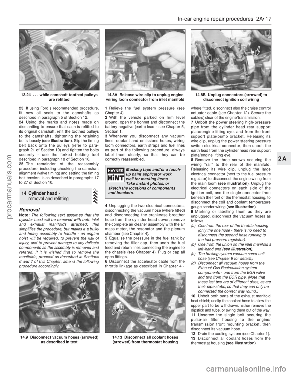
bolts loosely (see illustration). Slip the timing
belt back onto the pulleys (refer to para-
graph 21 of Section 10) and tighten the bolts
securely - use the forked holding tool
described in paragraph 18 of Section 10.
25The remainder of the reassembly
procedure, including checking the camshaft
alignment (valve timing) and setting the timing
belt tension, is as described in paragraphs 17
to 27 of Section 10.
Removal
Note:The following text assumes that the
cylinder head will be removed with both inlet
and exhaust manifolds attached; this
simplifies the procedure, but makes it a bulky
and heavy assembly to handle - an engine
hoist will be required, to prevent the risk of
injury, and to prevent damage to any delicate
components as the assembly is removed and
refitted. If it is wished first to remove the
manifolds, proceed as described in Sections
6 and 7 of this Chapter; amend the following
procedure accordingly.1Relieve the fuel system pressure (see
Chapter 4).
2With the vehicle parked on firm level
ground, open the bonnet and disconnect the
battery negative (earth) lead - see Chapter 5,
Section 1.
3Whenever you disconnect any vacuum
lines, coolant and emissions hoses, wiring
loom connectors, earth straps and fuel lines
as part of the following procedure, always
label them clearly, so that they can be
correctly reassembled.
4Unplugging the two electrical connectors,
disconnecting the vacuum hose (where fitted)
and disconnecting the crankcase breather
hose from the cylinder head cover, remove
the complete air cleaner assembly with the air
mass meter, the resonator and the plenum
chamber (see Chapter 4).
5Equalise the pressure in the fuel tank by
removing the filler cap, then undo the fuel
feed and return lines connecting the engine to
the chassis (see Chapter 4). Plug or cap all
open fittings.
6Disconnect the accelerator cable from the
throttle linkage as described in Chapter 4 -where fitted, disconnect also the cruise control
actuator cable (see Chapter 12). Secure the
cable(s) clear of the engine/transmission.
7Unbolt the power steering high-pressure
pipe from the cylinder head rear support
plate/engine lifting eye, and from the front
support plate/pump bracket. Releasing its
wire clip, unplug the power steering pressure
switch electrical connector, then unbolt the
earth lead from the cylinder head rear support
plate/engine lifting eye.
8Remove the three screws securing the
wiring “rail” to the rear of the manifold.
Releasing its wire clip, unplug the large
electrical connector (next to the fuel pressure
regulator) to disconnect the engine wiring from
the main loom (see illustration). Unplug the
electrical connectors on each side of the
ignition coil, and the single connector from
beneath the front of the thermostat housing, to
disconnect the coil and coolant temperature
gauge sender wiring (see illustration).
9Marking or labelling them as they are
unplugged, disconnect the vacuum hoses as
follows:
(a) One from the rear of the throttle housing
(only the one hose - there is no need to
disconnect the second hose running to
the fuel pressure regulator).
(b) One from the union on the inlet manifold’s
left-hand end (see illustration).
(c) The braking system vacuum servo unit
hose (see Chapter 9 for details).
(d) Disconnect all vacuum hoses from the
Exhaust Gas Recirculation system
components - one from the EGR valve
and two from the EGR pipe. (Note that
these last two are of different sizes, as are
their pipe stubs, so that they can only be
connected the correct way round.)
10Unbolt both parts of the exhaust manifold
heat shield; unclip the coolant hose to allow the
upper part to be withdrawn. Either remove the
dipstick and tube, or swing them out of the way.
11Unscrew the single bolt securing the
pulse-air filter housing to the engine/
transmission front mounting bracket, then
disconnect its vacuum hose.
12Drain the cooling system (see Chapter 1).
13Disconnect all coolant hoses from the
thermostat housing (see illustration).
14 Cylinder head -
removal and refitting
In-car engine repair procedures 2A•17
2A
14.9 Disconnect vacuum hoses (arrowed)
as described in text14.13 Disconnect all coolant hoses
(arrowed) from thermostat housing
13.24 . . . while camshaft toothed pulleys
are refitted14.8A Release wire clip to unplug engine
wiring loom connector from inlet manifold14.8B Unplug connectors (arrowed) to
disconnect ignition coil wiring
Masking tape and/or a touch-
up paint applicator work
well for marking items.
Take instant photos, or
sketch the locations of components
and brackets.
procarmanuals.com
Page 75 of 279
gear linkage heat shield. Reconnect the
gearchange linkage and transmission support
rods to the transmission, adjusting the linkage
using the marks made on removal (see
Chapter 7, Part A, for details).
56Re-install the remaining components and
fasteners in the reverse order of removal.
57Add coolant, engine oil and transmission
fluids as needed (see Chapter 1).
58Run the engine, and check for proper
operation and the absence of leaks. Shut off
the engine, and recheck the fluid levels.
59Remember that, since the front suspension
subframe and steering gear have been
disturbed, the wheel alignment and steering
angles must be checked fully and carefully as
soon as possible, with any necessary
adjustments being made. This operation is best
carried out by an experienced mechanic, using
proper checking equipment; the vehicle should
therefore be taken to a Ford dealer or similarly-
qualified person for attention.
1It is much easier to dismantle and work on
the engine if it is mounted on a portable engine
stand. These stands can often be hired from a
tool hire shop. Before the engine is mounted
on a stand, the flywheel/driveplate should be
removed (Part A of this Chapter, Section 21)
so that the stand bolts can be tightened into
the end of the cylinder block/crankcase.
2If a stand is not available, it is possible to
dismantle the engine with it mounted on
blocks, on a sturdy workbench or on the floor.
Be extra-careful not to tip or drop the engine
when working without a stand.
3If you are going to obtain a reconditioned
engine, all external components must be
removed first, to be transferred to the
replacement engine (just as they will if you are
doing a complete engine overhaul yourself).
Note:When removing the external
components from the engine, pay close
attention to details that may be helpful or
important during refitting. Note the fitted
position of gaskets, seals, spacers, pins,
washers, bolts and other small items.These
external components include the following:
(a) Alternator and brackets (Chapter 5).
(b) HT leads and spark plugs (Chapter 1).
(c) Thermostat and housing (Chapter 3).
(d) Dipstick tube.
(e) Fuel injection system components
(Chapter 4).
(f) All electrical switches and sensors - refer
to the appropriate Chapter.
(g) Inlet and exhaust manifolds (Part A of this
Chapter).
(h) Oil filter (Chapter 1).
(i) Engine/transmission mounting brackets
(Part A of this Chapter, Section 22).
(j) Flywheel/driveplate (Part A of this
Chapter, Section 21).
4If you are obtaining a “short” engine (whichconsists of the engine cylinder
block/crankcase, crankshaft, pistons and
connecting rods all assembled), then the
cylinder head, sump, oil pump, and timing belt
will have to be removed also.
5If you are planning a complete overhaul, the
engine can be dismantled and the internal
components removed in the following order.
(a) Inlet and exhaust manifolds (Part A of this
Chapter).
(b) Timing belt, toothed pulleys and
tensioner, and timing belt inner cover
(Part A of this Chapter).
(c) Cylinder head (Part A of this Chapter,
Section 14).
(d) Flywheel/driveplate (Part A of this
Chapter, Section 21).
(e) Sump (Part A of this Chapter, Section 15).
(f) Oil pump (Part A of this Chapter, Sec-
tion 16).
(g) Piston/connecting rod assemblies
(Section 9).
(h) Crankshaft (Section 10).
6Before beginning the dismantling andoverhaul procedures, make sure that you have
all of the correct tools necessary. Refer to the
introductory pages at the beginning of this
manual for further information.
Note:New and reconditioned cylinder heads
are available from the manufacturers, and
from engine overhaul specialists. Due to the
fact that some specialist tools are required for
the dismantling and inspection procedures,
and new components may not be readily
available (refer to Section 1 of this Part), it may
be more practical and economical for the
home mechanic to purchase a reconditioned
head, rather than to dismantle, inspect and
recondition the original head.
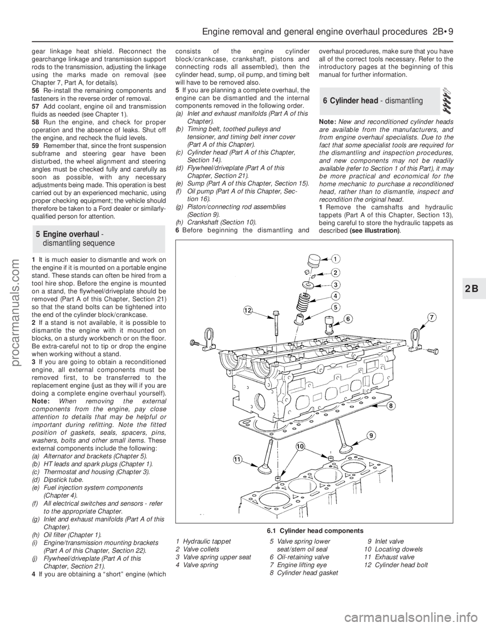
1Remove the camshafts and hydraulic
tappets (Part A of this Chapter, Section 13),
being careful to store the hydraulic tappets as
described (see illustration).
6 Cylinder head - dismantling
5 Engine overhaul-
dismantling sequence
Engine removal and general engine overhaul procedures 2B•9
2B
6.1 Cylinder head components
1 Hydraulic tappet
2 Valve collets
3 Valve spring upper seat
4 Valve spring5 Valve spring lower
seat/stem oil seal
6 Oil-retaining valve
7 Engine lifting eye
8 Cylinder head gasket9 Inlet valve
10 Locating dowels
11 Exhaust valve
12 Cylinder head bolt
procarmanuals.com
Page 269 of 279
6 Automatic transmission
REF•10Fault Finding
Note:Due to the complexity of the automatic transmission and its
electronic control system, it is difficult for the home mechanic to
properly diagnose and service this unit. For problems other than the
following, the vehicle should be taken to a dealer service department
or automatic transmission specialist.
Fluid leakage
m mAutomatic transmission fluid is usually deep red in colour. Fluid
leaks should not be confused with engine oil, which can easily be
blown onto the transmission by airflow.
m mTo determine the source of a leak, first remove all built-up dirt and
grime from the transmission housing and surrounding areas, using
a degreasing agent, or by steam-cleaning. Drive the vehicle at low
speed, so airflow will not blow the leak far from its source. Raise
and support the vehicle, and determine where the leak is coming
from. The following are common areas of leakage:
(a) Housing joints (Chapters 1 and 7, Part B).
(b) Dipstick tube (Chapters 1 and 7, Part B).
(c) Transmission-to-fluid cooler pipes/unions (Chapters 3 and 7,
Part B).
(d) Speedometer drive pinion O-ring (Chapter 7, Part B).
(e) Differential side gear oil seals (Chapter 7, Part B).
Transmission fluid brown, or has burned smell
m mTransmission fluid level low, or fluid in need of renewal (Chapter 1).
Transmission will not downshift (kickdown) with
accelerator pedal fully depressed
m mLow transmission fluid level (Chapter 1).
m mIncorrect selector cable adjustment (Chapter 7, Part B).
m mEngine management system fault (Chapters 1, 4, 5 and 6).
General gear selection problems
m
mChapter 7, Part B, deals with checking and adjusting the selector
cable on automatic transmissions. The following are common
problems which may be caused by a poorly-adjusted cable:
(a) Engine starting in gears other than Park or Neutral.
(b) Indicator on gear selector lever pointing to a gear other than the
one actually being used.
(c) Vehicle moves when in Park or Neutral.
(d) Poor gear shift quality or erratic gear changes.
Refer to Chapter 7, Part B for the selector cable adjustment
procedure.
Engine will not start in any gear, or starts in gears
other than Park or Neutral
m mIncorrect selector lever position sensor adjustment (Chapter 7,
Part B).
m mIncorrect selector cable adjustment (Chapter 7, Part B).
Transmission slips, shifts roughly, is noisy, or has no
drive in forward or reverse gears
m mThere are many probable causes for the above problems, but the
home mechanic should be concerned with only one possibility -
fluid level. Before taking the vehicle to a dealer or transmission
specialist, check the fluid level and condition of the fluid as
described in Chapter 1. Correct the fluid level as necessary, or
change the fluid if needed. If the problem persists, professional
help will be necessary.
7 Driveshafts
Clicking or knocking noise on turns (at slow speed
on full-lock)
m mLack of constant velocity joint lubricant (Chapter 8).
m mWorn outer constant velocity joint (Chapter 8).
Vibration when accelerating or decelerating
m
mWorn inner constant velocity joint (Chapter 8).
m mBent or distorted driveshaft (Chapter 8).
8 Braking system
Note:Before assuming that a brake problem exists, make sure that the tyres are in good condition and correctly inflated, that the front wheel
alignment is correct, and that the vehicle is not loaded with weight in an unequal manner. Apart from checking the condition of all pipe and hose
connections, any faults occurring on the Anti-lock Braking System (ABS) should be referred to a Ford dealer for diagnosis - the same applies to the
components of the Traction Control System (TCS).
Vehicle pulls to one side under braking
m mWorn, defective, damaged or contaminated front or rear brake
pads/shoes on one side (Chapter 1).
m mSeized or partially-seized front or rear brake caliper/wheel cylinder
piston (Chapter 9).
m mA mixture of brake pad/shoe lining materials fitted between sides
(Chapter 1).
m mBrake caliper mounting bolts loose (Chapter 9).
m mRear brake backplate mounting bolts loose (Chapter 9).
m mWorn or damaged steering or suspension components (Chap-
ter 10).
Noise (grinding or high-pitched squeal) when brakes
applied
m mBrake pad or shoe friction lining material worn down to metal
backing (Chapter 1).
m mExcessive corrosion of brake disc or drum (may be apparent after
the vehicle has been standing for some time) (Chapter 1).
m mForeign object (stone chipping, etc) trapped between brake disc
and splash shield (Chapter 1).
Excessive brake pedal travel
m mInoperative rear brake self-adjust mechanism (Chapter 9).
m mFaulty master cylinder (Chapter 9).
m mAir in hydraulic system (Chapter 9).
procarmanuals.com