rims FORD MONDEO 1993 Service Repair Manual
[x] Cancel search | Manufacturer: FORD, Model Year: 1993, Model line: MONDEO, Model: FORD MONDEO 1993Pages: 279, PDF Size: 12.71 MB
Page 32 of 279

of these components will cause loss of
lubricant, together with dirt and water entry,
resulting in rapid deterioration of the balljoints
or steering gear.
3Check the power-assisted steering fluid
hoses for chafing or deterioration, and the
pipe and hose unions for fluid leaks. Also
check for signs of fluid leakage under
pressure from the steering gear rubber
gaiters, which would indicate failed fluid seals
within the steering gear.
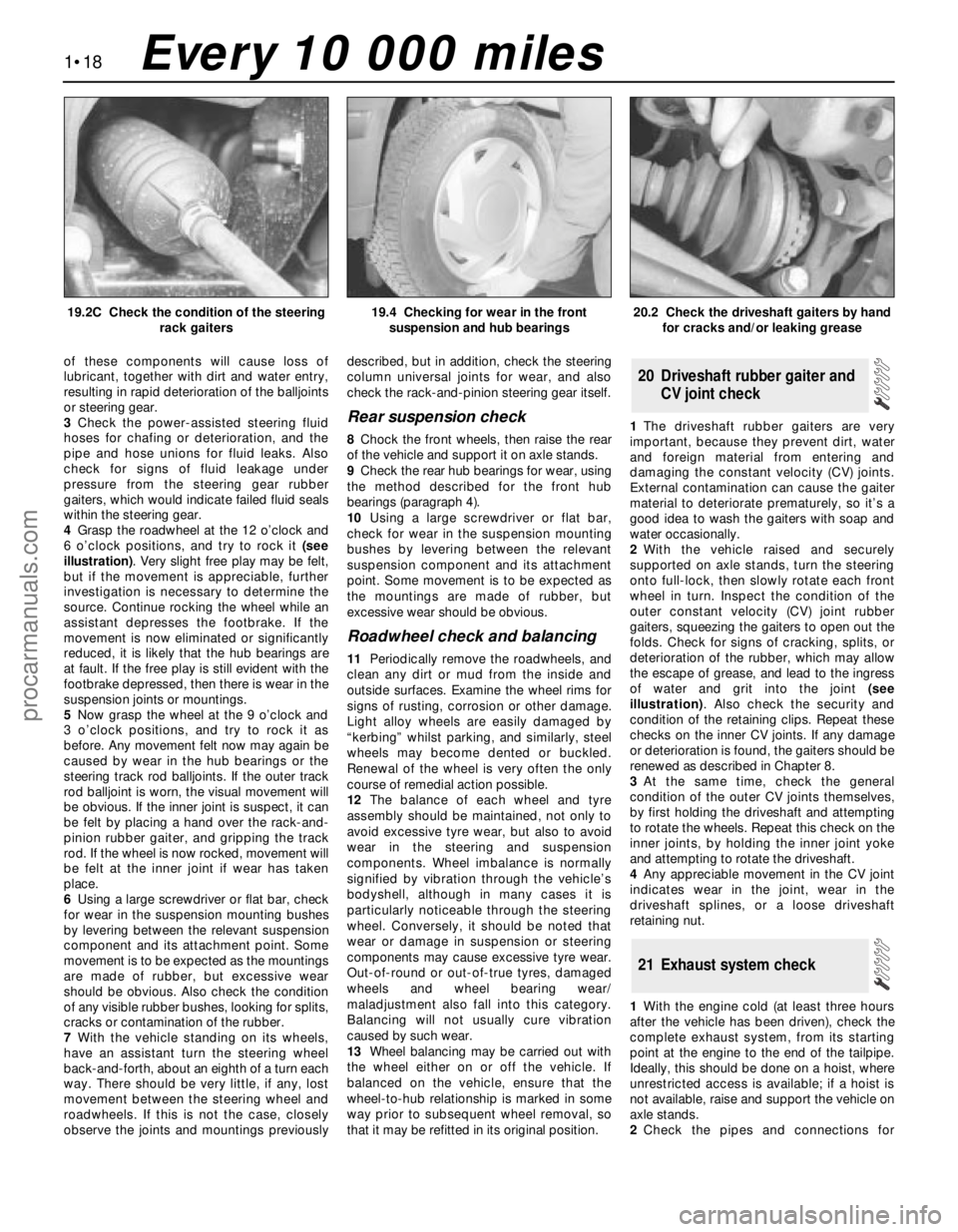
4Grasp the roadwheel at the 12 o’clock and
6 o’clock positions, and try to rock it (see
illustration). Very slight free play may be felt,
but if the movement is appreciable, further
investigation is necessary to determine the
source. Continue rocking the wheel while an
assistant depresses the footbrake. If the
movement is now eliminated or significantly
reduced, it is likely that the hub bearings are
at fault. If the free play is still evident with the
footbrake depressed, then there is wear in the
suspension joints or mountings.
5Now grasp the wheel at the 9 o’clock and
3 o’clock positions, and try to rock it as
before. Any movement felt now may again be
caused by wear in the hub bearings or the
steering track rod balljoints. If the outer track
rod balljoint is worn, the visual movement will
be obvious. If the inner joint is suspect, it can
be felt by placing a hand over the rack-and-
pinion rubber gaiter, and gripping the track
rod. If the wheel is now rocked, movement will
be felt at the inner joint if wear has taken
place.
6Using a large screwdriver or flat bar, check
for wear in the suspension mounting bushes
by levering between the relevant suspension
component and its attachment point. Some
movement is to be expected as the mountings
are made of rubber, but excessive wear
should be obvious. Also check the condition
of any visible rubber bushes, looking for splits,
cracks or contamination of the rubber.
7With the vehicle standing on its wheels,
have an assistant turn the steering wheel
back-and-forth, about an eighth of a turn each
way. There should be very little, if any, lost
movement between the steering wheel and
roadwheels. If this is not the case, closely
observe the joints and mountings previouslydescribed, but in addition, check the steering
column universal joints for wear, and also
check the rack-and-pinion steering gear itself.
Rear suspension check
8Chock the front wheels, then raise the rear
of the vehicle and support it on axle stands.
9Check the rear hub bearings for wear, using
the method described for the front hub
bearings (paragraph 4).
10Using a large screwdriver or flat bar,
check for wear in the suspension mounting
bushes by levering between the relevant
suspension component and its attachment
point. Some movement is to be expected as
the mountings are made of rubber, but
excessive wear should be obvious.
Roadwheel check and balancing
11Periodically remove the roadwheels, and
clean any dirt or mud from the inside and
outside surfaces. Examine the wheel rims for
signs of rusting, corrosion or other damage.
Light alloy wheels are easily damaged by
“kerbing” whilst parking, and similarly, steel
wheels may become dented or buckled.
Renewal of the wheel is very often the only
course of remedial action possible.
12The balance of each wheel and tyre
assembly should be maintained, not only to
avoid excessive tyre wear, but also to avoid
wear in the steering and suspension
components. Wheel imbalance is normally
signified by vibration through the vehicle’s
bodyshell, although in many cases it is
particularly noticeable through the steering
wheel. Conversely, it should be noted that
wear or damage in suspension or steering
components may cause excessive tyre wear.
Out-of-round or out-of-true tyres, damaged
wheels and wheel bearing wear/
maladjustment also fall into this category.
Balancing will not usually cure vibration
caused by such wear.
13Wheel balancing may be carried out with
the wheel either on or off the vehicle. If
balanced on the vehicle, ensure that the
wheel-to-hub relationship is marked in some
way prior to subsequent wheel removal, so
that it may be refitted in its original position.1The driveshaft rubber gaiters are very
important, because they prevent dirt, water
and foreign material from entering and
damaging the constant velocity (CV) joints.
External contamination can cause the gaiter
material to deteriorate prematurely, so it’s a
good idea to wash the gaiters with soap and
water occasionally.
2With the vehicle raised and securely
supported on axle stands, turn the steering
onto full-lock, then slowly rotate each front
wheel in turn. Inspect the condition of the
outer constant velocity (CV) joint rubber
gaiters, squeezing the gaiters to open out the
folds. Check for signs of cracking, splits, or
deterioration of the rubber, which may allow
the escape of grease, and lead to the ingress
of water and grit into the joint (see
illustration). Also check the security and
condition of the retaining clips. Repeat these
checks on the inner CV joints. If any damage
or deterioration is found, the gaiters should be
renewed as described in Chapter 8.
3At the same time, check the general
condition of the outer CV joints themselves,
by first holding the driveshaft and attempting
to rotate the wheels. Repeat this check on the
inner joints, by holding the inner joint yoke
and attempting to rotate the driveshaft.
4Any appreciable movement in the CV joint
indicates wear in the joint, wear in the
driveshaft splines, or a loose driveshaft
retaining nut.
1With the engine cold (at least three hours
after the vehicle has been driven), check the
complete exhaust system, from its starting
point at the engine to the end of the tailpipe.
Ideally, this should be done on a hoist, where
unrestricted access is available; if a hoist is
not available, raise and support the vehicle on
axle stands.
2Check the pipes and connections for
21 Exhaust system check
20 Driveshaft rubber gaiter and
CV joint check
1•18
19.2C Check the condition of the steering
rack gaiters19.4 Checking for wear in the front
suspension and hub bearings20.2 Check the driveshaft gaiters by hand
for cracks and/or leaking grease
Every 10 000 miles
procarmanuals.com
Page 46 of 279

specifications were available from Ford, but a
typical reading would be in excess of 12 bars.
All cylinders should produce very similar
pressures; any difference greater than 10%
indicates the existence of a fault. Note that the
compression should build up quickly in a
healthy engine; low compression on the first
stroke, followed by gradually-increasing
pressure on successive strokes, indicates worn
piston rings. A low compression reading on the
first stroke, which does not build up during
successive strokes, indicates leaking valves or a
blown head gasket (a cracked head could also
be the cause). Deposits on the undersides of the
valve heads can also cause low compression.
8If the pressure in any cylinder is
considerably lower than the others, introduce
a teaspoonful of clean oil into that cylinder
through its spark plug hole, and repeat the
test.
9If the addition of oil temporarily improves
the compression pressure, this indicates that
bore or piston wear is responsible for the
pressure loss. No improvement suggests that
leaking or burnt valves, or a blown head
gasket, may be to blame.
10A low reading from two adjacent cylinders
is almost certainly due to the head gasket
having blown between them; the presence of
coolant in the engine oil will confirm this.
11If one cylinder is about 20 percent lower
than the others and the engine has a slightly
rough idle, a worn camshaft lobe or faulty
hydraulic tappet could be the cause.
12If the compression is unusually high, the
combustion chambers are probably coated
with carbon deposits. If this is the case, the
cylinder head should be removed and
decarbonised.
13On completion of the test, refit the spark
plugs, then reconnect the ignition system and
fuel pump.
General
1Top Dead Centre (TDC) is the highest point
in its travel up-and-down its cylinder bore
that each piston reaches as the crankshaftrotates. While each piston reaches TDC both
at the top of the compression stroke and
again at the top of the exhaust stroke, for the
purpose of timing the engine, TDC refers to
the piston position (usually No 1 piston) at the
top of its compression stroke.
2It is useful for several servicing procedures
to be able to position the engine at TDC.
3No 1 piston and cylinder are at the right-
hand (timing belt) end of the engine (right-
and left-hand are always quoted as seen from
the driver’s seat). Note that the crankshaft
rotates clockwise when viewed from the
right-hand side of the vehicle.
Locating TDC
4Remove all the spark plugs (Chapter 1).
5Disconnect both battery leads - see
Chapter 5, Section 1 - unless the starter
motor is to be used to turn the engine.
6Apply the handbrake and ensure that the
transmission is in neutral, then jack up the
front right-hand side of the vehicle and
support on an axle stand. Remove the
roadwheel.
7Remove the auxiliary drivebelt cover (see
Chapter 1) to expose the crankshaft pulley
and timing marks.
8It is best to rotate the crankshaft using a
spanner applied to the crankshaft pulley bolt;
however, it is possible also to use the starter
motor (switched on either by an assistant
using the ignition key, or by using a remote
starter switch) to bring the engine close to
TDC, then finish with a spanner. If the starter
is used, be sure to disconnect the battery
leads immediately it is no longer required.
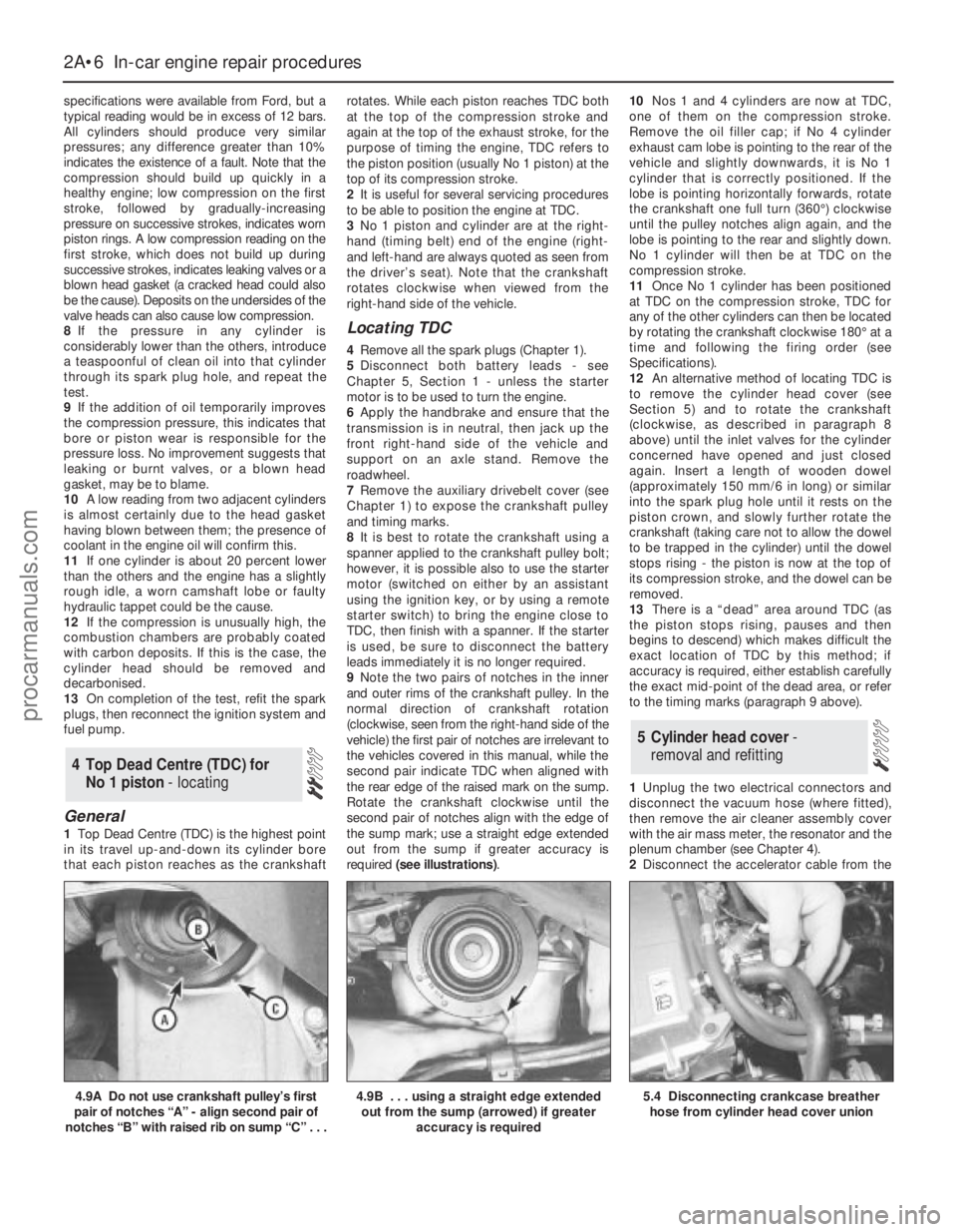
9Note the two pairs of notches in the inner
and outer rims of the crankshaft pulley. In the
normal direction of crankshaft rotation
(clockwise, seen from the right-hand side of the
vehicle) the first pair of notches are irrelevant to
the vehicles covered in this manual, while the
second pair indicate TDC when aligned with
the rear edge of the raised mark on the sump.
Rotate the crankshaft clockwise until the
second pair of notches align with the edge of
the sump mark; use a straight edge extended
out from the sump if greater accuracy is
required (see illustrations).10Nos 1 and 4 cylinders are now at TDC,
one of them on the compression stroke.
Remove the oil filler cap; if No 4 cylinder
exhaust cam lobe is pointing to the rear of the
vehicle and slightly downwards, it is No 1
cylinder that is correctly positioned. If the
lobe is pointing horizontally forwards, rotate
the crankshaft one full turn (360°) clockwise
until the pulley notches align again, and the
lobe is pointing to the rear and slightly down.
No 1 cylinder will then be at TDC on the
compression stroke.
11Once No 1 cylinder has been positioned
at TDC on the compression stroke, TDC for
any of the other cylinders can then be located
by rotating the crankshaft clockwise 180° at a
time and following the firing order (see
Specifications).
12An alternative method of locating TDC is
to remove the cylinder head cover (see
Section 5) and to rotate the crankshaft
(clockwise, as described in paragraph 8
above) until the inlet valves for the cylinder
concerned have opened and just closed
again. Insert a length of wooden dowel
(approximately 150 mm/6 in long) or similar
into the spark plug hole until it rests on the
piston crown, and slowly further rotate the
crankshaft (taking care not to allow the dowel
to be trapped in the cylinder) until the dowel
stops rising - the piston is now at the top of
its compression stroke, and the dowel can be
removed.
13There is a “dead” area around TDC (as
the piston stops rising, pauses and then
begins to descend) which makes difficult the
exact location of TDC by this method; if
accuracy is required, either establish carefully
the exact mid-point of the dead area, or refer
to the timing marks (paragraph 9 above).
1Unplug the two electrical connectors and
disconnect the vacuum hose (where fitted),
then remove the air cleaner assembly cover
with the air mass meter, the resonator and the
plenum chamber (see Chapter 4).
2Disconnect the accelerator cable from the
5 Cylinder head cover-
removal and refitting
4 Top Dead Centre (TDC) for
No 1 piston - locating
2A•6 In-car engine repair procedures
4.9A Do not use crankshaft pulley’s first
pair of notches “A” - align second pair of
notches “B” with raised rib on sump “C” . . .4.9B . . . using a straight edge extended
out from the sump (arrowed) if greater
accuracy is required5.4 Disconnecting crankcase breather
hose from cylinder head cover union
procarmanuals.com
Page 144 of 279

Ignition timing and base idle
speed check
Note:The following procedure is a check only,
essentially of the ECU. Both the ignition timing
and the base idle speed are controlled by the
ECU. The ignition timing is not adjustable at
all; the base idle speed is set in production,
and should not be altered.
38If the fault code read-out (with any checks
resulting from it) has not eliminated the fault,
the next step is to check the ECU’s control of
the ignition timing and the base idle speed.
This task requires the use of a Ford STAR
tester (a proprietary fault code reader can be
used only if it is capable of inducing the ECU
to enter its “Service Adjustment Programme”),
coupled with an accurate tachometer and a
good-quality timing light. Without this
equipment, the task is not possible; the
vehicle must be taken to a Ford dealer for
attention.
39To make the check, apply the handbrake,
switch off the air conditioning (where fitted)
and any other electrical loads (lights, heated
rear window, etc), then select neutral (manual
transmission) or the “P” position (automatic
transmission). Start the engine, and warm it
up to normal operating temperature. The
radiator electric cooling fan must be running
continuously while the check is made; this
should be activated by the ECU, when
prompted by the tester. Switch off the engine,
and connect the test equipment as directed
by the manufacturer - refer to paragraph 26
above for details of STAR tester connection.
40Raise and support the front of the vehicle
securely, and remove the auxiliary drivebelt
cover (see Chapter 1). Emphasise the two
pairs of notches in the inner and outer rims of
the crankshaft pulley, using white paint. Note
that an ignition timing reference mark is not
provided on the pulley - in the normal
direction of crankshaft rotation (clockwise,
seen from the right-hand side of the vehicle)
the first pair of notches are irrelevant to the
vehicles covered in this manual, while the
second pair indicate Top Dead Centre (TDC)
when aligned with the rear edge of the raised
mark on the sump; when checking the ignition
timing, therefore, the (rear edge of the) sumpmark should appear just before the TDC
notches (see Part A of Chapter 2, Section 4,
for further information if required).
41Start the engine and allow it to idle. Work
through the engine-running test procedure
until the ECU enters its “Service Adjustment
Programme” - see paragraph 35 above.
42Use the timing light to check that the
timing marks appear approximately as
outlined above at idle speed. Do not spend
too much time on this check; if the timing
appears to be incorrect, the system may have
a fault, and a full system test must be carried
out (see below) to establish its cause.
43Using the tachometer, check that the
base idle speed is as given in the
Specifications Section of Chapter 4.
44If the recorded speed differs significantly
from the specified value, check for air leaks,
as described in the preliminary checks
(paragraphs 15 to 18 above), or any other
faults which might cause the discrepancy.
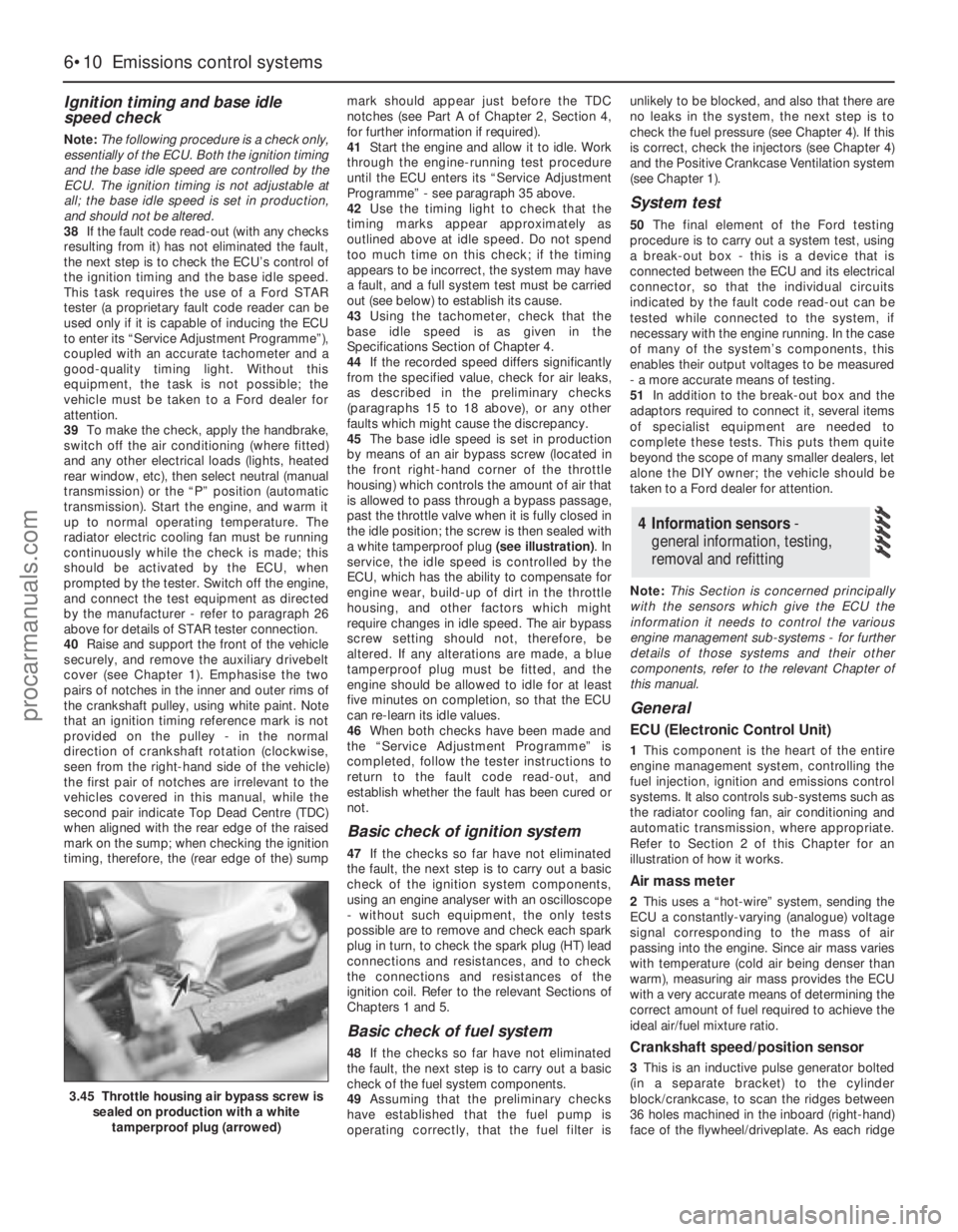
45The base idle speed is set in production
by means of an air bypass screw (located in
the front right-hand corner of the throttle
housing) which controls the amount of air that
is allowed to pass through a bypass passage,
past the throttle valve when it is fully closed in
the idle position; the screw is then sealed with
a white tamperproof plug (see illustration). In
service, the idle speed is controlled by the
ECU, which has the ability to compensate for
engine wear, build-up of dirt in the throttle
housing, and other factors which might
require changes in idle speed. The air bypass
screw setting should not, therefore, be
altered. If any alterations are made, a blue
tamperproof plug must be fitted, and the
engine should be allowed to idle for at least
five minutes on completion, so that the ECU
can re-learn its idle values.
46When both checks have been made and
the “Service Adjustment Programme” is
completed, follow the tester instructions to
return to the fault code read-out, and
establish whether the fault has been cured or
not.
Basic check of ignition system
47If the checks so far have not eliminated
the fault, the next step is to carry out a basic
check of the ignition system components,
using an engine analyser with an oscilloscope
- without such equipment, the only tests
possible are to remove and check each spark
plug in turn, to check the spark plug (HT) lead
connections and resistances, and to check
the connections and resistances of the
ignition coil. Refer to the relevant Sections of
Chapters 1 and 5.
Basic check of fuel system
48If the checks so far have not eliminated
the fault, the next step is to carry out a basic
check of the fuel system components.
49Assuming that the preliminary checks
have established that the fuel pump is
operating correctly, that the fuel filter isunlikely to be blocked, and also that there are
no leaks in the system, the next step is to
check the fuel pressure (see Chapter 4). If this
is correct, check the injectors (see Chapter 4)
and the Positive Crankcase Ventilation system
(see Chapter 1).
System test
50The final element of the Ford testing
procedure is to carry out a system test, using
a break-out box - this is a device that is
connected between the ECU and its electrical
connector, so that the individual circuits
indicated by the fault code read-out can be
tested while connected to the system, if
necessary with the engine running. In the case
of many of the system’s components, this
enables their output voltages to be measured
- a more accurate means of testing.
51In addition to the break-out box and the
adaptors required to connect it, several items
of specialist equipment are needed to
complete these tests. This puts them quite
beyond the scope of many smaller dealers, let
alone the DIY owner; the vehicle should be
taken to a Ford dealer for attention.
Note:This Section is concerned principally
with the sensors which give the ECU the
information it needs to control the various
engine management sub-systems - for further
details of those systems and their other
components, refer to the relevant Chapter of
this manual.
General
ECU (Electronic Control Unit)
1This component is the heart of the entire
engine management system, controlling the
fuel injection, ignition and emissions control
systems. It also controls sub-systems such as
the radiator cooling fan, air conditioning and
automatic transmission, where appropriate.
Refer to Section 2 of this Chapter for an
illustration of how it works.
Air mass meter
2This uses a “hot-wire” system, sending the
ECU a constantly-varying (analogue) voltage
signal corresponding to the mass of air
passing into the engine. Since air mass varies
with temperature (cold air being denser than
warm), measuring air mass provides the ECU
with a very accurate means of determining the
correct amount of fuel required to achieve the
ideal air/fuel mixture ratio.
Crankshaft speed/position sensor
3This is an inductive pulse generator bolted
(in a separate bracket) to the cylinder
block/crankcase, to scan the ridges between
36 holes machined in the inboard (right-hand)
face of the flywheel/driveplate. As each ridge
4 Information sensors -
general information, testing,
removal and refitting
6•10 Emissions control systems
3.45 Throttle housing air bypass screw is
sealed on production with a white
tamperproof plug (arrowed)
procarmanuals.com
Page 195 of 279

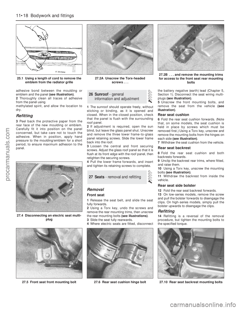
adhesive bond between the moulding or
emblem and the panel (see illustration).
2Thoroughly clean all traces of adhesive
from the panel using
methylated spirit, and allow the location to
dry.
Refitting
3Peel back the protective paper from the
rear face of the new moulding or emblem.
Carefully fit it into position on the panel
concerned, but take care not to touch the
adhesive. When in position, apply hand
pressure to the moulding/emblem for a short
period, to ensure maximum adhesion to the
panel.1The sunroof should operate freely, without
sticking or binding, as it is opened and
closed. When in the closed position, check
that the panel is flush with the surrounding
roof panel.
2If adjustment is required, open the sun
blind, but leave the glass panel shut. Unscrew
and remove the three lower frame-to-glass
panel retaining screws. Slide the lower frame
back into the roof.
3Loosen the central and front securing
screws. Adjust the glass roof panel so that it is
flush at its front edge with the roof panel, then
retighten the securing screws.
4Pull the lower frame forwards, and insert
and tighten its retaining screws to complete.
Removal
Front seat
1Release the seat belt, and slide the seat
fully forwards.
2Using a Torx key, undo the screws and
remove the rear mounting trims, then unscrew
the rear mounting bolts (see illustrations).
3Slide the seat fully rearwards.
4Where electric seats are fitted, disconnectthe battery negative (earth) lead (Chapter 5,
Section 1). Disconnect the seat wiring multi-
plugs (see illustration).
5Unscrew the front mounting bolts, and
remove the seat from the vehicle (see
illustration).
Rear seat cushion
6Fold the rear seat cushion forwards. (Note
that, on some models, the seat cushion is
held in place by screws which must be
removed first.) Using a Torx key, unscrew and
remove the mounting bolts from the hinges on
each side (see illustration).
7Withdraw the seat cushion from the vehicle.
Rear seat backrest
8Fold the rear seat cushion and both
backrests forwards.
9Unclip the backrest rear trims, where fitted,
and raise them.
10Using a Torx key, unscrew the mounting
bolts (see illustration).
11Withdraw the backrest from inside the
vehicle.
Rear seat side bolster
12Fold the rear seat backrest forwards.
13On low-series models, remove the screw
and pull the bolster forwards to disengage the
clips. On high-series models, simply pull the
bolster upwards to disengage the clips.
Refitting
14Refitting is a reversal of the removal
procedure, but tighten the mounting bolts to
the specified torque.
27 Seats - removal and refitting
26 Sunroof - general
information and adjustment
11•18 Bodywork and fittings
25.1 Using a length of cord to remove the
emblem from the radiator grille27.2A Unscrew the Torx-headed
screws . . .27.2B . . . and remove the mounting trims
for access to the front seat rear mounting
bolts
27.5 Front seat front mounting bolt
27.4 Disconnecting an electric seat multi-
plug
27.6 Rear seat cushion hinge bolt27.10 Rear seat backrest mounting bolts
procarmanuals.com