roof FORD MONDEO 1993 Service Repair Manual
[x] Cancel search | Manufacturer: FORD, Model Year: 1993, Model line: MONDEO, Model: FORD MONDEO 1993Pages: 279, PDF Size: 12.71 MB
Page 6 of 279

0•6General Dimensions & Weights
Dimensions
Overall length:
Saloon, Hatchback . . . . . . . . . . . . . . . . . . . . . . . . . . . . . . . . . . . . . 4481 mm
Estate . . . . . . . . . . . . . . . . . . . . . . . . . . . . . . . . . . . . . . . . . . . . . . . 4631 mm
Overall width - including mirrors . . . . . . . . . . . . . . . . . . . . . . . . . . . . . 1925 mm
Overall height - at kerb weight:
Saloon, Hatchback . . . . . . . . . . . . . . . . . . . . . . . . . . . . . . . . . . . . . 1403 to 1435 mm
Estate . . . . . . . . . . . . . . . . . . . . . . . . . . . . . . . . . . . . . . . . . . . . . . . 1416 to 1501 mm
Wheelbase . . . . . . . . . . . . . . . . . . . . . . . . . . . . . . . . . . . . . . . . . . . . . 2704 mm
Front track - all models . . . . . . . . . . . . . . . . . . . . . . . . . . . . . . . . . . . . 1503 mm
Rear track:
Saloon, Hatchback . . . . . . . . . . . . . . . . . . . . . . . . . . . . . . . . . . . . . 1486 to 1487 mm
Estate . . . . . . . . . . . . . . . . . . . . . . . . . . . . . . . . . . . . . . . . . . . . . . . 1504 mm
Turning circle . . . . . . . . . . . . . . . . . . . . . . . . . . . . . . . . . . . . . . . . . . . 10.9 m
Weights
Kerb weight:
1.6 Saloon, Hatchback models . . . . . . . . . . . . . . . . . . . . . . . . . . . . 1215 to 1250 kg
1.6 Estate models . . . . . . . . . . . . . . . . . . . . . . . . . . . . . . . . . . . . . . 1265 to 1275 kg
1.8 Saloon, Hatchback models:
Manual transmission . . . . . . . . . . . . . . . . . . . . . . . . . . . . . . . . . . 1225 to 1260 kg
Automatic transmission . . . . . . . . . . . . . . . . . . . . . . . . . . . . . . . . 1260 to 1280 kg
1.8 Estate models:
Manual transmission . . . . . . . . . . . . . . . . . . . . . . . . . . . . . . . . . . 1275 to 1285 kg
Automatic transmission . . . . . . . . . . . . . . . . . . . . . . . . . . . . . . . . 1305 kg
2.0 Saloon, Hatchback models:
Manual transmission . . . . . . . . . . . . . . . . . . . . . . . . . . . . . . . . . . 1250 to 1310 kg
Automatic transmission . . . . . . . . . . . . . . . . . . . . . . . . . . . . . . . . 1285 to 1340 kg
2.0 Estate models:
Manual transmission . . . . . . . . . . . . . . . . . . . . . . . . . . . . . . . . . . 1295 to 1335 kg
Automatic transmission . . . . . . . . . . . . . . . . . . . . . . . . . . . . . . . . 1330 to 1415 kg
Maximum gross vehicle weight:
Saloon, Hatchback:
1.6 models . . . . . . . . . . . . . . . . . . . . . . . . . . . . . . . . . . . . . . . . . . 1725 kg
1.8 Saloon models, automatic transmission . . . . . . . . . . . . . . . . . 1750 kg
2.0 models, automatic transmission . . . . . . . . . . . . . . . . . . . . . . . 1800 kg
All others . . . . . . . . . . . . . . . . . . . . . . . . . . . . . . . . . . . . . . . . . . . 1775 kg
Estate:
1.6 models, 2.0 models with manual transmission . . . . . . . . . . . . 1900 kg
All others . . . . . . . . . . . . . . . . . . . . . . . . . . . . . . . . . . . . . . . . . . . 1925 kg
Maximum roof rack load:
Estate models with integral roof rack . . . . . . . . . . . . . . . . . . . . . . . . 100 kg
All others . . . . . . . . . . . . . . . . . . . . . . . . . . . . . . . . . . . . . . . . . . . . . 75 kg
Maximum towing weight . . . . . . . . . . . . . . . . . . . . . . . . . . . . . . . . . . . 1500 kg
Trailer nose weight limit . . . . . . . . . . . . . . . . . . . . . . . . . . . . . . . . . . . . 75 kg
procarmanuals.com
Page 49 of 279
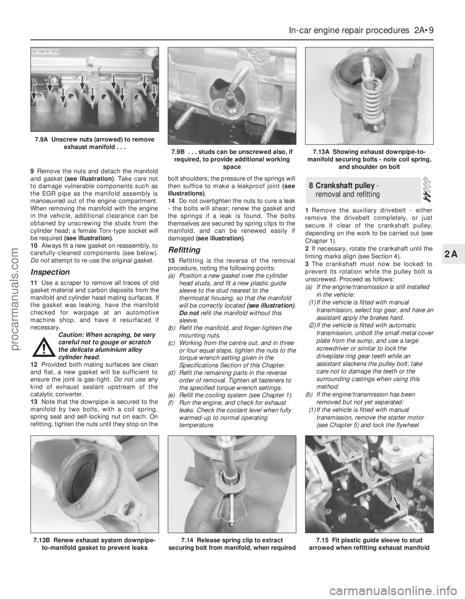
9Remove the nuts and detach the manifold
and gasket (see illustration). Take care not
to damage vulnerable components such as
the EGR pipe as the manifold assembly is
manoeuvred out of the engine compartment.
When removing the manifold with the engine
in the vehicle, additional clearance can be
obtained by unscrewing the studs from the
cylinder head; a female Torx-type socket will
be required (see illustration).
10Always fit a new gasket on reassembly, to
carefully-cleaned components (see below).
Do notattempt to re-use the original gasket.
Inspection
11Use a scraper to remove all traces of old
gasket material and carbon deposits from the
manifold and cylinder head mating surfaces. If
the gasket was leaking, have the manifold
checked for warpage at an automotive
machine shop, and have it resurfaced if
necessary.
Caution: When scraping, be very
careful not to gouge or scratch
the delicate aluminium alloy
cylinder head.
12Provided both mating surfaces are clean
and flat, a new gasket will be sufficient to
ensure the joint is gas-tight. Do notuse any
kind of exhaust sealant upstream of the
catalytic converter.
13Note that the downpipe is secured to the
manifold by two bolts, with a coil spring,
spring seat and self-locking nut on each. On
refitting, tighten the nuts until they stop on thebolt shoulders; the pressure of the springs will
then suffice to make a leakproof joint (see
illustrations).
14Do not overtighten the nuts to cure a leak
- the bolts will shear; renew the gasket and
the springs if a leak is found. The bolts
themselves are secured by spring clips to the
manifold, and can be renewed easily if
damaged (see illustration).
Refitting
15Refitting is the reverse of the removal
procedure, noting the following points:
(a) Position a new gasket over the cylinder
head studs, and fit a new plastic guide
sleeve to the stud nearest to the
thermostat housing, so that the manifold
will be correctly located (see illustration).
Do notrefit the manifold without this
sleeve.
(b) Refit the manifold, and finger-tighten the
mounting nuts.
(c) Working from the centre out, and in three
or four equal steps, tighten the nuts to the
torque wrench setting given in the
Specifications Section of this Chapter.
(d) Refit the remaining parts in the reverse
order of removal. Tighten all fasteners to
the specified torque wrench settings.
(e) Refill the cooling system (see Chapter 1).
(f) Run the engine, and check for exhaust
leaks. Check the coolant level when fully
warmed-up to normal operating
temperature.1Remove the auxiliary drivebelt - either
remove the drivebelt completely, or just
secure it clear of the crankshaft pulley,
depending on the work to be carried out (see
Chapter 1).
2If necessary, rotate the crankshaft until the
timing marks align (see Section 4).
3The crankshaft must now be locked to
prevent its rotation while the pulley bolt is
unscrewed. Proceed as follows:
(a) If the engine/transmission is still installed
in the vehicle:
(1) If the vehicle is fitted with manual
transmission, select top gear, and have an
assistant apply the brakes hard.
(2) If the vehicle is fitted with automatic
transmission, unbolt the small metal cover
plate from the sump, and use a large
screwdriver or similar to lock the
driveplate ring gear teeth while an
assistant slackens the pulley bolt; take
care not to damage the teeth or the
surrounding castings when using this
method.
(b) If the engine/transmission has been
removed but not yet separated:
(1) If the vehicle is fitted with manual
transmission, remove the starter motor
(see Chapter 5) and lock the flywheel
8 Crankshaft pulley -
removal and refitting
In-car engine repair procedures 2A•9
2A
7.13B Renew exhaust system downpipe-
to-manifold gasket to prevent leaks7.14 Release spring clip to extract
securing bolt from manifold, when required7.15 Fit plastic guide sleeve to stud
arrowed when refitting exhaust manifold
7.9A Unscrew nuts (arrowed) to remove
exhaust manifold . . .
7.9B . . . studs can be unscrewed also, if
required, to provide additional working
space7.13A Showing exhaust downpipe-to-
manifold securing bolts - note coil spring,
and shoulder on bolt
procarmanuals.com
Page 110 of 279
Idle-increase solenoid valve
Check
43If this valve is thought to be faulty, unplug
its electrical connector and disconnect its
vacuum hoses, then connect a battery directly
across the valve’s terminals. Check that air
can flow through the valve’s passages when
the solenoid is energised, and that nothing
can pass when the solenoid is not energised.
Alternatively, connect an ohmmeter to
measure the resistance between the valve’s
terminals, and compare this reading to that
listed in the Specifications Section at the
beginning of this Chapter. Renew the valve if
it is faulty (see illustration).
44The solenoid’s diode is fitted to control
any voltage “spikes” which might occur as the
solenoid is switched off. A faulty diode would
not, therefore, necessarily interfere with the
operation of the valve. If the diode is thought
to be faulty, however, it can be checked by
unplugging it and connecting an ohmmeter
across its terminals, to check that continuity
exists in one direction only. If continuity is
found in both directions, or in neither, the
diode is faulty, and must be renewed.
Renewal
45If better access is required, remove the
plenum chamber (see Section 4).
46Disconnect the battery negative (earth)
lead - see Section 1 of Chapter 5.
46Unplug the valve’s electrical connector.
Unclip the valve from the bulkhead, then
disconnect its vacuum hoses and withdraw it.
47Refitting is the reverse of the removal
procedure.
Warning: Inspection and repair of
exhaust system components
should be done only after enough
time has elapsed after driving the vehicle
to allow the system components to cool
completely. This applies particularly to the
catalytic converter, which runs at very
high temperatures. Also, when working
under the vehicle, make sure it is securely
supported on axle stands.
1The exhaust system is composed of an
exhaust manifold, the front downpipe and
catalytic converter, and a rear section
incorporating two silencers (three on some
versions) and the tailpipe assembly. The
service replacement exhaust system consists
of three or four sections: the front
downpipe/catalytic converter, the
intermediate pipe and front silencer, and the
tailpipe and rear silencer. On some versions,
the tailpipe is in two pieces, with two rear
silencers. The system is suspended
throughout its entire length by rubber
mountings.
2If any of these parts are damaged ordeteriorated, excessive noise and vibration
will occur.
3Conduct regular inspections of the exhaust
system, to keep it safe and quiet. Look for any
damaged or bent parts, open seams, holes,
loose connections, excessive corrosion, or
other defects which could allow exhaust
fumes to enter the vehicle. Deteriorated
exhaust system components should not be
repaired - they should be replaced with new
parts.
4If the exhaust system components are
extremely corroded or rusted together, they
will probably have to be cut from the exhaust
system. The most convenient way of
accomplishing this is to have a quick-fit
exhaust repair specialist remove the corroded
sections. If, however, you want to save money
by doing it yourself (and you don’t have an
oxy/acetylene welding outfit with a cutting
torch), simply cut off the old components with
a hacksaw. If you have compressed air,
special pneumatic cutting chisels can also be
used. If you do decide to tackle the job at
home, be sure to wear eye protection, to
protect your eyes from metal chips, and work
gloves, to protect your hands. If the
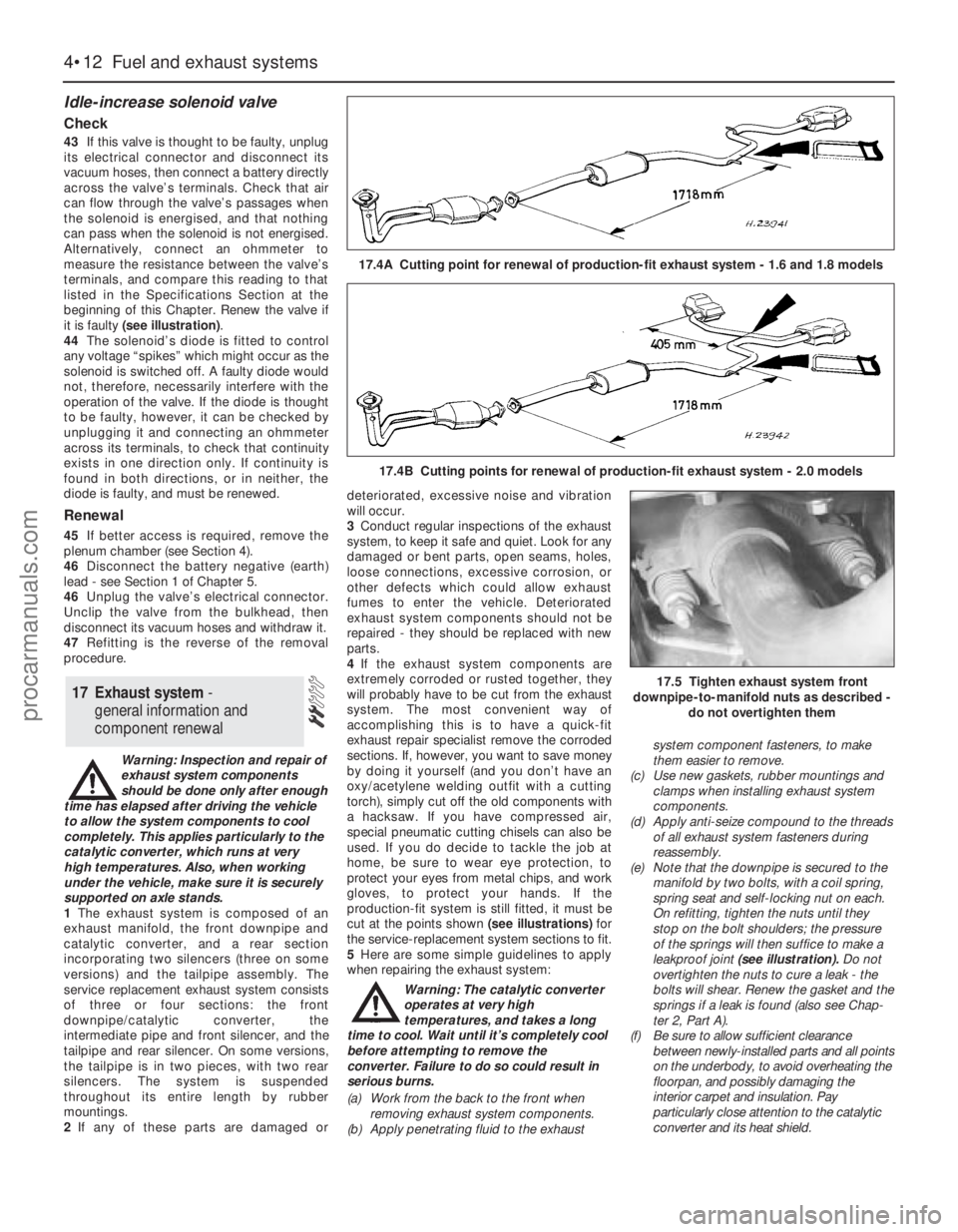
production-fit system is still fitted, it must be
cut at the points shown (see illustrations) for
the service-replacement system sections to fit.
5Here are some simple guidelines to apply
when repairing the exhaust system:
Warning: The catalytic converter
operates at very high
temperatures, and takes a long
time to cool. Wait until it’s completely cool
before attempting to remove the
converter. Failure to do so could result in
serious burns.
(a) Work from the back to the front when
removing exhaust system components.
(b) Apply penetrating fluid to the exhaustsystem component fasteners, to make
them easier to remove.
(c) Use new gaskets, rubber mountings and
clamps when installing exhaust system
components.
(d) Apply anti-seize compound to the threads
of all exhaust system fasteners during
reassembly.
(e) Note that the downpipe is secured to the
manifold by two bolts, with a coil spring,
spring seat and self-locking nut on each.
On refitting, tighten the nuts until they
stop on the bolt shoulders; the pressure
of the springs will then suffice to make a
leakproof joint (see illustration). Do not
overtighten the nuts to cure a leak - the
bolts will shear. Renew the gasket and the
springs if a leak is found (also see Chap-
ter 2, Part A).
(f) Be sure to allow sufficient clearance
between newly-installed parts and all points
on the underbody, to avoid overheating the
floorpan, and possibly damaging the
interior carpet and insulation. Pay
particularly close attention to the catalytic
converter and its heat shield.
17 Exhaust system -
general information and
component renewal
4•12 Fuel and exhaust systems
17.4A Cutting point for renewal of production-fit exhaust system - 1.6 and 1.8 models
17.4B Cutting points for renewal of production-fit exhaust system - 2.0 models
17.5 Tighten exhaust system front
downpipe-to-manifold nuts as described -
do not overtighten them
procarmanuals.com
Page 112 of 279
General information
The engine electrical systems include all
ignition, charging and starting components.
Because of their engine-related functions,
these components are discussed separately
from body electrical devices such as the
lights, the instruments, etc (which are
included in Chapter 12).
Precautions
Always observe the following precautions
when working on the electrical system:
(a) Be extremely careful when servicing
engine electrical components. They are
easily damaged if checked, connected or
handled improperly.
(b) Never leave the ignition switched on for
long periods of time when the engine is
not running.
(c) Don’t disconnect the battery leads while
the engine is running.
(d) Maintain correct polarity when connecting
a battery lead from another vehicle during
jump starting - see the “Booster battery
(jump) starting” section at the front of this
manual.
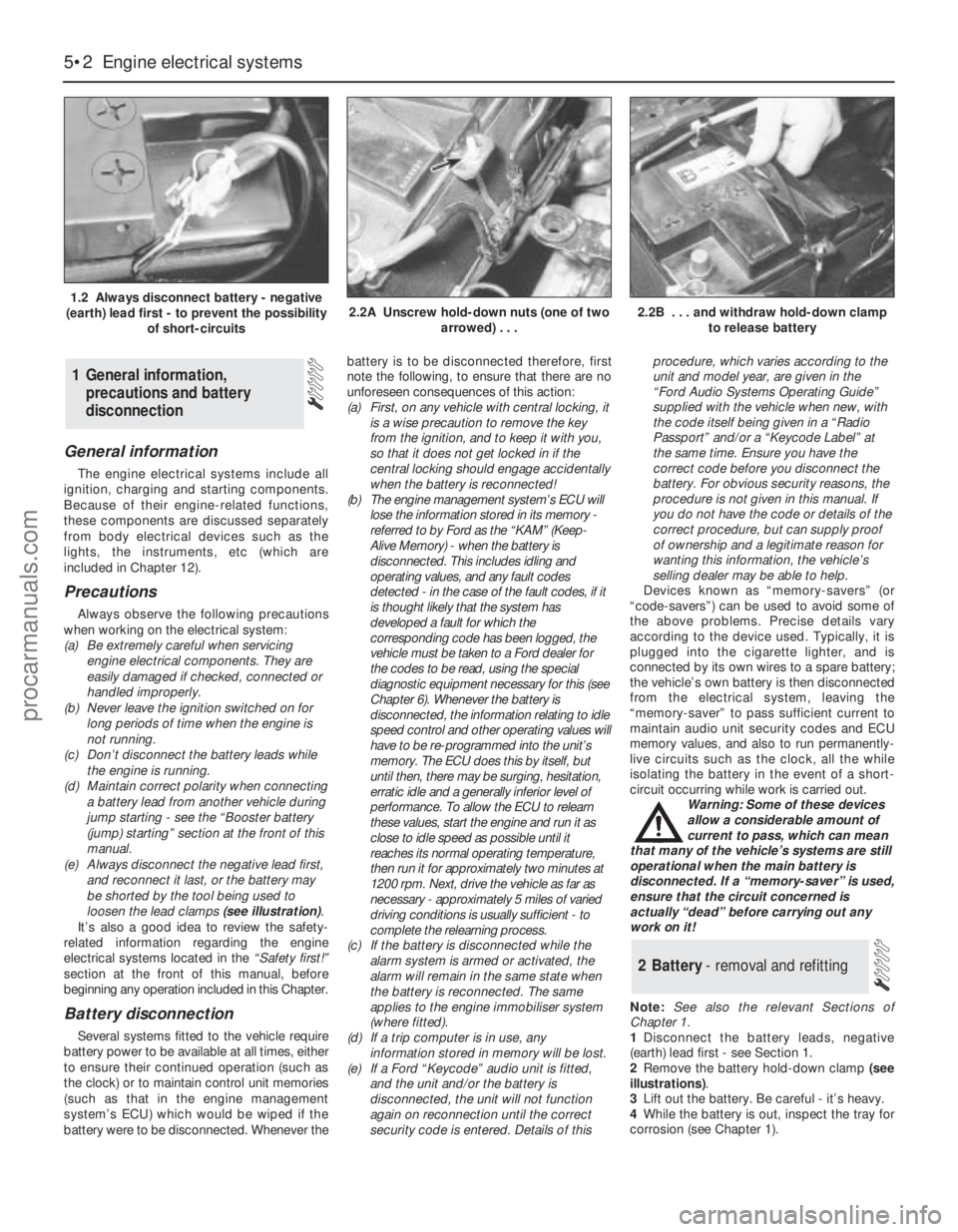
(e) Always disconnect the negative lead first,
and reconnect it last, or the battery may
be shorted by the tool being used to
loosen the lead clamps (see illustration).
It’s also a good idea to review the safety-
related information regarding the engine
electrical systems located in the “Safety first!”
section at the front of this manual, before
beginning any operation included in this Chapter.
Battery disconnection
Several systems fitted to the vehicle require
battery power to be available at all times, either
to ensure their continued operation (such as
the clock) or to maintain control unit memories
(such as that in the engine management
system’s ECU) which would be wiped if the
battery were to be disconnected. Whenever thebattery is to be disconnected therefore, first
note the following, to ensure that there are no
unforeseen consequences of this action:
(a) First, on any vehicle with central locking, it
is a wise precaution to remove the key
from the ignition, and to keep it with you,
so that it does not get locked in if the
central locking should engage accidentally
when the battery is reconnected!
(b) The engine management system’s ECU will
lose the information stored in its memory -
referred to by Ford as the “KAM” (Keep-
Alive Memory) - when the battery is
disconnected. This includes idling and
operating values, and any fault codes
detected - in the case of the fault codes, if it
is thought likely that the system has
developed a fault for which the
corresponding code has been logged, the
vehicle must be taken to a Ford dealer for
the codes to be read, using the special
diagnostic equipment necessary for this (see
Chapter 6). Whenever the battery is
disconnected, the information relating to idle
speed control and other operating values will
have to be re-programmed into the unit’s
memory. The ECU does this by itself, but
until then, there may be surging, hesitation,
erratic idle and a generally inferior level of
performance. To allow the ECU to relearn
these values, start the engine and run it as
close to idle speed as possible until it
reaches its normal operating temperature,
then run it for approximately two minutes at
1200 rpm. Next, drive the vehicle as far as
necessary - approximately 5 miles of varied
driving conditions is usually sufficient - to
complete the relearning process.
(c) If the battery is disconnected while the
alarm system is armed or activated, the
alarm will remain in the same state when
the battery is reconnected. The same
applies to the engine immobiliser system
(where fitted).
(d) If a trip computer is in use, any
information stored in memory will be lost.
(e) If a Ford “Keycode” audio unit is fitted,
and the unit and/or the battery is
disconnected, the unit will not function
again on reconnection until the correct
security code is entered. Details of thisprocedure, which varies according to the
unit and model year, are given in the
“Ford Audio Systems Operating Guide”
supplied with the vehicle when new, with
the code itself being given in a “Radio
Passport” and/or a “Keycode Label” at
the same time. Ensure you have the
correct code before you disconnect the
battery. For obvious security reasons, the
procedure is not given in this manual. If
you do not have the code or details of the
correct procedure, but can supply proof
of ownership and a legitimate reason for
wanting this information, the vehicle’s
selling dealer may be able to help.
Devices known as “memory-savers” (or
“code-savers”) can be used to avoid some of
the above problems. Precise details vary
according to the device used. Typically, it is
plugged into the cigarette lighter, and is
connected by its own wires to a spare battery;
the vehicle’s own battery is then disconnected
from the electrical system, leaving the
“memory-saver” to pass sufficient current to
maintain audio unit security codes and ECU
memory values, and also to run permanently-
live circuits such as the clock, all the while
isolating the battery in the event of a short-
circuit occurring while work is carried out.
Warning: Some of these devices
allow a considerable amount of
current to pass, which can mean
that many of the vehicle’s systems are still
operational when the main battery is
disconnected. If a “memory-saver” is used,
ensure that the circuit concerned is
actually “dead” before carrying out any
work on it!
Note:See also the relevant Sections of
Chapter 1.
1Disconnect the battery leads, negative
(earth) lead first - see Section 1.
2Remove the battery hold-down clamp (see
illustrations).
3Lift out the battery. Be careful - it’s heavy.
4While the battery is out, inspect the tray for
corrosion (see Chapter 1).
2 Battery- removal and refitting
1 General information,
precautions and battery
disconnection
5•2 Engine electrical systems
1.2 Always disconnect battery - negative
(earth) lead first - to prevent the possibility
of short-circuits2.2A Unscrew hold-down nuts (one of two
arrowed) . . .2.2B . . . and withdraw hold-down clamp
to release battery
procarmanuals.com
Page 144 of 279
Ignition timing and base idle
speed check
Note:The following procedure is a check only,
essentially of the ECU. Both the ignition timing
and the base idle speed are controlled by the
ECU. The ignition timing is not adjustable at
all; the base idle speed is set in production,
and should not be altered.
38If the fault code read-out (with any checks
resulting from it) has not eliminated the fault,
the next step is to check the ECU’s control of
the ignition timing and the base idle speed.
This task requires the use of a Ford STAR
tester (a proprietary fault code reader can be
used only if it is capable of inducing the ECU
to enter its “Service Adjustment Programme”),
coupled with an accurate tachometer and a
good-quality timing light. Without this
equipment, the task is not possible; the
vehicle must be taken to a Ford dealer for
attention.
39To make the check, apply the handbrake,
switch off the air conditioning (where fitted)
and any other electrical loads (lights, heated
rear window, etc), then select neutral (manual
transmission) or the “P” position (automatic
transmission). Start the engine, and warm it
up to normal operating temperature. The
radiator electric cooling fan must be running
continuously while the check is made; this
should be activated by the ECU, when
prompted by the tester. Switch off the engine,
and connect the test equipment as directed
by the manufacturer - refer to paragraph 26
above for details of STAR tester connection.
40Raise and support the front of the vehicle
securely, and remove the auxiliary drivebelt
cover (see Chapter 1). Emphasise the two
pairs of notches in the inner and outer rims of
the crankshaft pulley, using white paint. Note
that an ignition timing reference mark is not
provided on the pulley - in the normal
direction of crankshaft rotation (clockwise,
seen from the right-hand side of the vehicle)
the first pair of notches are irrelevant to the
vehicles covered in this manual, while the
second pair indicate Top Dead Centre (TDC)
when aligned with the rear edge of the raised
mark on the sump; when checking the ignition
timing, therefore, the (rear edge of the) sumpmark should appear just before the TDC
notches (see Part A of Chapter 2, Section 4,
for further information if required).
41Start the engine and allow it to idle. Work
through the engine-running test procedure
until the ECU enters its “Service Adjustment
Programme” - see paragraph 35 above.
42Use the timing light to check that the
timing marks appear approximately as
outlined above at idle speed. Do not spend
too much time on this check; if the timing
appears to be incorrect, the system may have
a fault, and a full system test must be carried
out (see below) to establish its cause.
43Using the tachometer, check that the
base idle speed is as given in the
Specifications Section of Chapter 4.
44If the recorded speed differs significantly
from the specified value, check for air leaks,
as described in the preliminary checks
(paragraphs 15 to 18 above), or any other
faults which might cause the discrepancy.
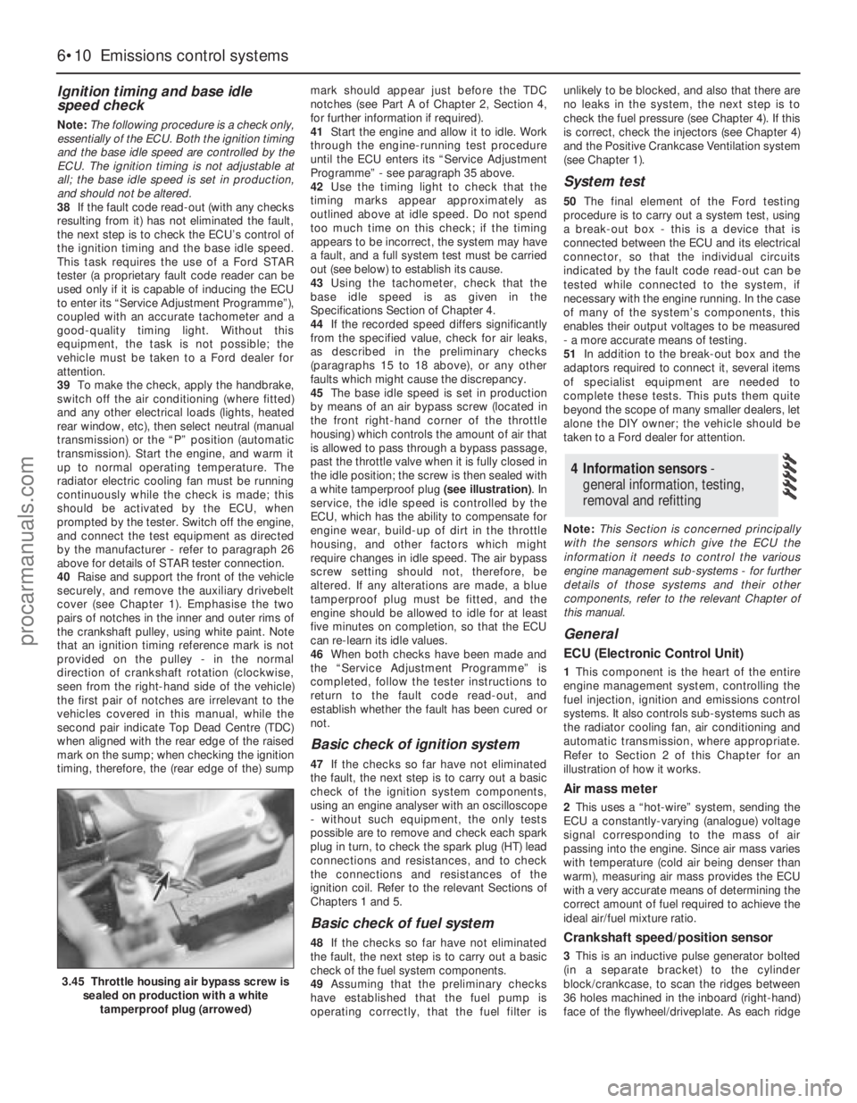
45The base idle speed is set in production
by means of an air bypass screw (located in
the front right-hand corner of the throttle
housing) which controls the amount of air that
is allowed to pass through a bypass passage,
past the throttle valve when it is fully closed in
the idle position; the screw is then sealed with
a white tamperproof plug (see illustration). In
service, the idle speed is controlled by the
ECU, which has the ability to compensate for
engine wear, build-up of dirt in the throttle
housing, and other factors which might
require changes in idle speed. The air bypass
screw setting should not, therefore, be
altered. If any alterations are made, a blue
tamperproof plug must be fitted, and the
engine should be allowed to idle for at least
five minutes on completion, so that the ECU
can re-learn its idle values.
46When both checks have been made and
the “Service Adjustment Programme” is
completed, follow the tester instructions to
return to the fault code read-out, and
establish whether the fault has been cured or
not.
Basic check of ignition system
47If the checks so far have not eliminated
the fault, the next step is to carry out a basic
check of the ignition system components,
using an engine analyser with an oscilloscope
- without such equipment, the only tests
possible are to remove and check each spark
plug in turn, to check the spark plug (HT) lead
connections and resistances, and to check
the connections and resistances of the
ignition coil. Refer to the relevant Sections of
Chapters 1 and 5.
Basic check of fuel system
48If the checks so far have not eliminated
the fault, the next step is to carry out a basic
check of the fuel system components.
49Assuming that the preliminary checks
have established that the fuel pump is
operating correctly, that the fuel filter isunlikely to be blocked, and also that there are
no leaks in the system, the next step is to
check the fuel pressure (see Chapter 4). If this
is correct, check the injectors (see Chapter 4)
and the Positive Crankcase Ventilation system
(see Chapter 1).
System test
50The final element of the Ford testing
procedure is to carry out a system test, using
a break-out box - this is a device that is
connected between the ECU and its electrical
connector, so that the individual circuits
indicated by the fault code read-out can be
tested while connected to the system, if
necessary with the engine running. In the case
of many of the system’s components, this
enables their output voltages to be measured
- a more accurate means of testing.
51In addition to the break-out box and the
adaptors required to connect it, several items
of specialist equipment are needed to
complete these tests. This puts them quite
beyond the scope of many smaller dealers, let
alone the DIY owner; the vehicle should be
taken to a Ford dealer for attention.
Note:This Section is concerned principally
with the sensors which give the ECU the
information it needs to control the various
engine management sub-systems - for further
details of those systems and their other
components, refer to the relevant Chapter of
this manual.
General
ECU (Electronic Control Unit)
1This component is the heart of the entire
engine management system, controlling the
fuel injection, ignition and emissions control
systems. It also controls sub-systems such as
the radiator cooling fan, air conditioning and
automatic transmission, where appropriate.
Refer to Section 2 of this Chapter for an
illustration of how it works.
Air mass meter
2This uses a “hot-wire” system, sending the
ECU a constantly-varying (analogue) voltage
signal corresponding to the mass of air
passing into the engine. Since air mass varies
with temperature (cold air being denser than
warm), measuring air mass provides the ECU
with a very accurate means of determining the
correct amount of fuel required to achieve the
ideal air/fuel mixture ratio.
Crankshaft speed/position sensor
3This is an inductive pulse generator bolted
(in a separate bracket) to the cylinder
block/crankcase, to scan the ridges between
36 holes machined in the inboard (right-hand)
face of the flywheel/driveplate. As each ridge
4 Information sensors -
general information, testing,
removal and refitting
6•10 Emissions control systems
3.45 Throttle housing air bypass screw is
sealed on production with a white
tamperproof plug (arrowed)
procarmanuals.com
Page 178 of 279
Chapter 11 Bodywork and fittings
Body side-trim mouldings and adhesive emblems - removal
and refitting . . . . . . . . . . . . . . . . . . . . . . . . . . . . . . . . . . . . . . . . . . 25
Bonnet - removal, refitting and adjustment . . . . . . . . . . . . . . . . . . . . 8
Bonnet lock - removal, refitting and adjustment . . . . . . . . . . . . . . . . 10
Bonnet release cable and lever - removal and refitting . . . . . . . . . . . 9
Boot lid - removal and refitting . . . . . . . . . . . . . . . . . . . . . . . . . . . . . 18
Boot lid lock components - removal and refitting . . . . . . . . . . . . . . . 19
Bumpers - removal and refitting . . . . . . . . . . . . . . . . . . . . . . . . . . . . 6
Central locking system components - testing, removal and refitting . 23
Centre console - removal and refitting . . . . . . . . . . . . . . . . . . . . . . . 30
Door - removal and refitting . . . . . . . . . . . . . . . . . . . . . . . . . . . . . . . 15
Door handle and lock components - removal and refitting . . . . . . . . 14
Door inner trim panel - removal and refitting . . . . . . . . . . . . . . . . . . 11
Door window glass - removal and refitting . . . . . . . . . . . . . . . . . . . . 12
Door window regulator - removal and refitting . . . . . . . . . . . . . . . . . 13
Exterior mirror and glass - removal and refitting . . . . . . . . . . . . . . . . 16
Facia - removal and refitting . . . . . . . . . . . . . . . . . . . . . . . . . . . . . . . 33
General information . . . . . . . . . . . . . . . . . . . . . . . . . . . . . . . . . . . . . . 1Glovebox - removal and refitting . . . . . . . . . . . . . . . . . . . . . . . . . . . . 32
Interior mirror - removal and refitting . . . . . . . . . . . . . . . . . . . . . . . . 17
Interior trim panels - removal and refitting . . . . . . . . . . . . . . . . . . . . 29
Maintenance - bodywork and underframe . . . . . . . . . . . . . . . . . . . . 2
Maintenance - upholstery and carpets . . . . . . . . . . . . . . . . . . . . . . . 3
Major body damage - repair . . . . . . . . . . . . . . . . . . . . . . . . . . . . . . . 5
Minor body damage - repair . . . . . . . . . . . . . . . . . . . . . . . . . . . . . . . 4
Overhead console - removal and refitting . . . . . . . . . . . . . . . . . . . . . 31
Radiator grille - removal and refitting . . . . . . . . . . . . . . . . . . . . . . . . 7
Seat belts - removal and refitting . . . . . . . . . . . . . . . . . . . . . . . . . . . 28
Seats - removal and refitting . . . . . . . . . . . . . . . . . . . . . . . . . . . . . . . 27
Sunroof - general information and adjustment . . . . . . . . . . . . . . . . . 26
Tailgate - removal and refitting . . . . . . . . . . . . . . . . . . . . . . . . . . . . . 20
Tailgate lock components - removal and refitting . . . . . . . . . . . . . . . 22
Tailgate support strut - removal and refitting . . . . . . . . . . . . . . . . . . 21
Wheel arch liner - removal and refitting . . . . . . . . . . . . . . . . . . . . . . 34
Windscreen and fixed windows - removal and refitting . . . . . . . . . . 24
Torque wrench settingsNm lbf ft
Bonnet and tailgate hinges . . . . . . . . . . . . . . . . . . . . . . . . . . . . . . . . . . . 24 18
Boot lid . . . . . . . . . . . . . . . . . . . . . . . . . . . . . . . . . . . . . . . . . . . . . . . . . . 10 7
Front seat mounting bolts . . . . . . . . . . . . . . . . . . . . . . . . . . . . . . . . . . . . 38 28
Seat belt mounting nuts and bolts . . . . . . . . . . . . . . . . . . . . . . . . . . . . . 38 28
Bumper mounting nuts . . . . . . . . . . . . . . . . . . . . . . . . . . . . . . . . . . . . . . 10 7
11•1
Easy,suitable for
novice with little
experienceFairly easy,suitable
for beginner with
some experienceFairly difficult,suitable
for competent DIY
mechanicDifficult,suitable for
experienced DIY
mechanicVery difficult,
suitable for expert DIY
or professional
Degrees of difficulty
Specifications Contents
11
The bodyshell and underframe on all
models is of all-steel welded construction,
incorporating progressive crumple zones at
the front and rear, and a rigid centre safety
cell. The bulkhead behind the engine
compartment incorporates crash grooves
which determine its energy-absorption
characteristics, and special beams to prevent
the intrusion of the front wheels into the
passenger compartment during a serious
accident. All passenger doors incorporate
side impact bars.
All sheet metal surfaces which are prone tocorrosion are galvanized. The painting
process includes a base colour which closely
matches the final topcoat, so that any stone
damage is not noticeable.
Hatchback, Saloon and Estate versions are
available. The front section of the vehicle up to
the “B” pillar is identical on all models.
Automatic seat belts are fitted to all models,
and the front seat belt stalks are mounted on
automatic tensioners (also known as
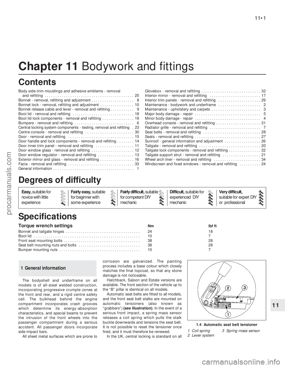
“grabbers”) (see illustration). In the event of a
serious front impact, a spring mass sensor
releases a coil spring which pulls the stalk
buckle downwards and tensions the seat belt.
It is not possible to reset the tensioner once
fired, and it must therefore be renewed.
In the UK, central locking is standard on all
1 General information
1.4 Automatic seat belt tensioner
1 Coil spring 3 Spring mass sensor
2 Lever system
procarmanuals.com
Page 192 of 279
Removal
Lock barrel
1Disconnect the battery negative (earth) lead
(Chapter 5, Section 1).
2With the boot lid open, remove the luggage
space trim from the right-hand rear corner.
3Remove the screws, and prise out the rear
light trim cover from the guides.
4Release the door-ajar sensor from the clip
near the lock.
5Slide the outer cable from the lock bracket.
Raise the inner cable until it is aligned with the
slot in the barrel lever, and disconnect it.
6Pull out the lock locating spring clip.
7Detach the cable mounting bracket from
the barrel, and remove the barrel.
Lock
8Disconnect the battery negative (earth) lead
(Chapter 5, Section 1).
9With the boot lid open, prise out the clips
and remove the trim from inside the boot lid.
10Release the door-ajar sensor from the clip
near the lock.
11Using a Torx key, unscrew the lock
mounting screws, and withdraw the lock for
access to the cables.
12Disconnect both the inner and outer
cables from the lock bracket.13Prise open the plastic lip, and remove the
central locking control rod.
14Withdraw the lock assembly.
Refitting
Lock barrel and lock
15Refitting is a reversal of the removal
procedure.
Removal
Hatchback
1Disconnect the battery negative (earth) lead
(Chapter 5, Section 1). Open the tailgate.
2The tailgate may be unbolted from the
hinges and the hinges left in position, or the
hinges may be detached from the roof panel
by unscrewing the mounting nuts. In the latter
case, carefully pull down the rear edge of the
headlining for access to the nuts. Take care
not to damage the headlining.
3Remove the parcel shelf left-hand support
bracket as follows. Fold the rear seat
forwards, and disconnect the left-hand seat
pull cable from the bracket and clips.
Unscrew the screws and remove the bracket.
4Pull up the rear seat side bolster, then
carefully remove the side trim from the left-
hand side of the luggage area. On low-series
models, the bolster is retained with a screw.5Separate the tailgate wiring loom multi-
plugs, located on the left-hand side of the
luggage compartment, on top of the wheel
arch.
6Unclip and remove the upper trim panel
from the inside of the tailgate. Also remove
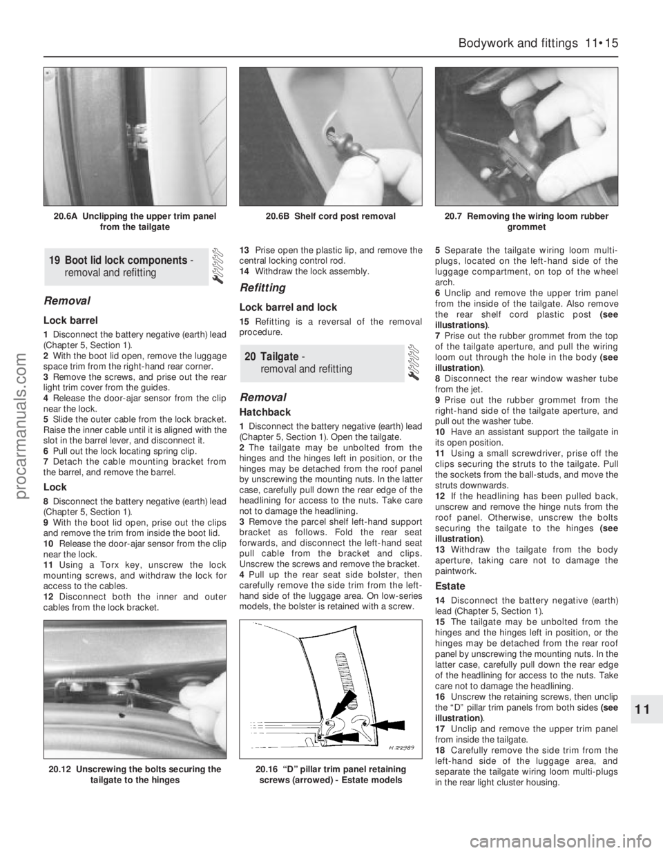
the rear shelf cord plastic post (see
illustrations).
7Prise out the rubber grommet from the top
of the tailgate aperture, and pull the wiring
loom out through the hole in the body (see
illustration).
8Disconnect the rear window washer tube
from the jet.
9Prise out the rubber grommet from the
right-hand side of the tailgate aperture, and
pull out the washer tube.
10Have an assistant support the tailgate in
its open position.
11Using a small screwdriver, prise off the
clips securing the struts to the tailgate. Pull
the sockets from the ball-studs, and move the
struts downwards.
12If the headlining has been pulled back,
unscrew and remove the hinge nuts from the
roof panel. Otherwise, unscrew the bolts
securing the tailgate to the hinges (see
illustration).
13Withdraw the tailgate from the body
aperture, taking care not to damage the
paintwork.
Estate
14Disconnect the battery negative (earth)
lead (Chapter 5, Section 1).
15The tailgate may be unbolted from the
hinges and the hinges left in position, or the
hinges may be detached from the rear roof
panel by unscrewing the mounting nuts. In the
latter case, carefully pull down the rear edge
of the headlining for access to the nuts. Take
care not to damage the headlining.
16Unscrew the retaining screws, then unclip
the “D” pillar trim panels from both sides (see
illustration).
17Unclip and remove the upper trim panel
from inside the tailgate.
18Carefully remove the side trim from the
left-hand side of the luggage area, and
separate the tailgate wiring loom multi-plugs
in the rear light cluster housing.
20 Tailgate -
removal and refitting
19 Boot lid lock components-
removal and refitting
Bodywork and fittings 11•15
11
20.12 Unscrewing the bolts securing the
tailgate to the hinges20.16 “D” pillar trim panel retaining
screws (arrowed) - Estate models
20.6A Unclipping the upper trim panel
from the tailgate20.6B Shelf cord post removal20.7 Removing the wiring loom rubber
grommet
procarmanuals.com
Page 193 of 279
19Attach a strong fine cord to the end of the
wiring loom, to act as an aid to guiding the
wiring through the tailgate when it is refitted.
20Prise the rubber grommet from the top
left-hand side of the tailgate aperture, and pull
out the wiring loom. Untie the cord, leaving it
in position in the “D” pillar.
21Disconnect the rear window washer tube
from the jet. Pull out the rubber grommet, and
remove the tube.
22Have an assistant support the tailgate in
its open position.
23Using a small screwdriver, prise off the
clip securing the struts to the tailgate. Pull the
sockets from the ball-studs, and move the
struts downwards.
24Unscrew and remove the hinge nuts from
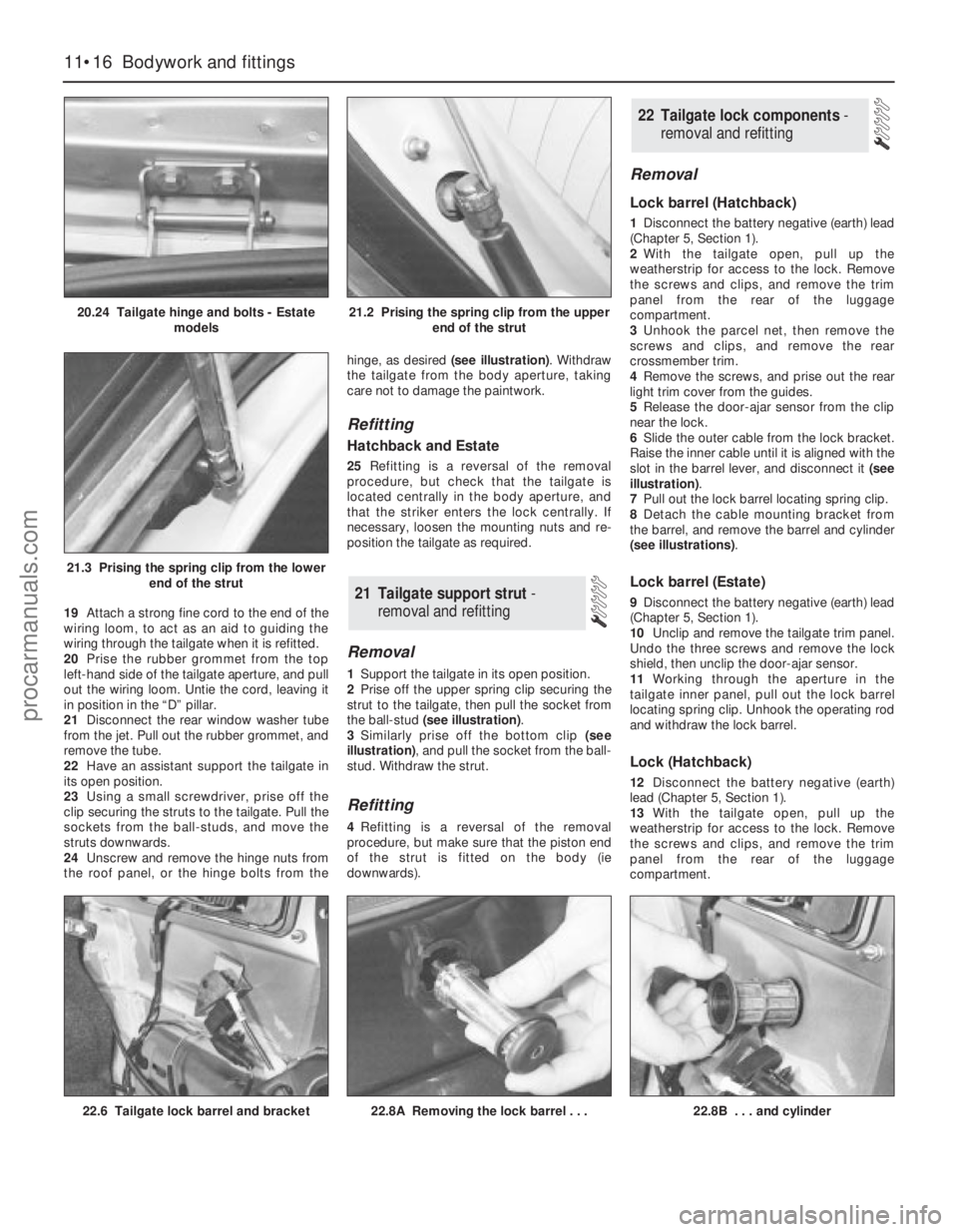
the roof panel, or the hinge bolts from thehinge, as desired (see illustration). Withdraw
the tailgate from the body aperture, taking
care not to damage the paintwork.
Refitting
Hatchback and Estate
25Refitting is a reversal of the removal
procedure, but check that the tailgate is
located centrally in the body aperture, and
that the striker enters the lock centrally. If
necessary, loosen the mounting nuts and re-
position the tailgate as required.
Removal
1Support the tailgate in its open position.
2Prise off the upper spring clip securing the
strut to the tailgate, then pull the socket from
the ball-stud (see illustration).
3Similarly prise off the bottom clip (see
illustration), and pull the socket from the ball-
stud. Withdraw the strut.
Refitting
4Refitting is a reversal of the removal
procedure, but make sure that the piston end
of the strut is fitted on the body (ie
downwards).
Removal
Lock barrel (Hatchback)
1Disconnect the battery negative (earth) lead
(Chapter 5, Section 1).
2With the tailgate open, pull up the
weatherstrip for access to the lock. Remove
the screws and clips, and remove the trim
panel from the rear of the luggage
compartment.
3Unhook the parcel net, then remove the
screws and clips, and remove the rear
crossmember trim.
4Remove the screws, and prise out the rear
light trim cover from the guides.
5Release the door-ajar sensor from the clip
near the lock.
6Slide the outer cable from the lock bracket.
Raise the inner cable until it is aligned with the
slot in the barrel lever, and disconnect it (see
illustration).
7Pull out the lock barrel locating spring clip.
8Detach the cable mounting bracket from
the barrel, and remove the barrel and cylinder
(see illustrations).
Lock barrel (Estate)
9Disconnect the battery negative (earth) lead
(Chapter 5, Section 1).
10Unclip and remove the tailgate trim panel.
Undo the three screws and remove the lock
shield, then unclip the door-ajar sensor.
11Working through the aperture in the
tailgate inner panel, pull out the lock barrel
locating spring clip. Unhook the operating rod
and withdraw the lock barrel.
Lock (Hatchback)
12Disconnect the battery negative (earth)
lead (Chapter 5, Section 1).
13With the tailgate open, pull up the
weatherstrip for access to the lock. Remove
the screws and clips, and remove the trim
panel from the rear of the luggage
compartment.
22 Tailgate lock components -
removal and refitting
21 Tailgate support strut-
removal and refitting
11•16 Bodywork and fittings
20.24 Tailgate hinge and bolts - Estate
models21.2 Prising the spring clip from the upper
end of the strut
21.3 Prising the spring clip from the lower
end of the strut
22.6 Tailgate lock barrel and bracket22.8A Removing the lock barrel . . .22.8B . . . and cylinder
procarmanuals.com
Page 195 of 279
adhesive bond between the moulding or
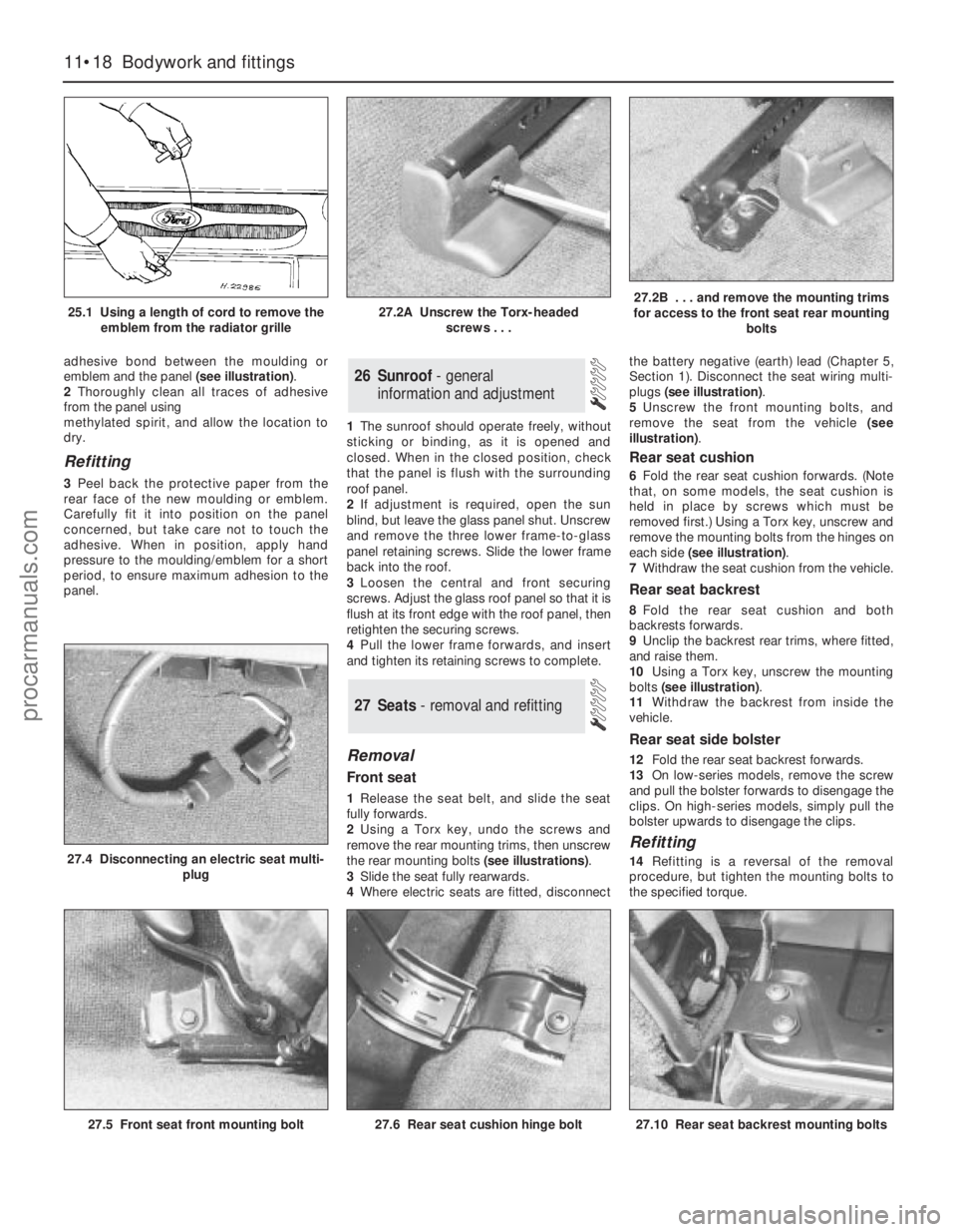
emblem and the panel (see illustration).
2Thoroughly clean all traces of adhesive
from the panel using
methylated spirit, and allow the location to
dry.
Refitting
3Peel back the protective paper from the
rear face of the new moulding or emblem.
Carefully fit it into position on the panel
concerned, but take care not to touch the
adhesive. When in position, apply hand
pressure to the moulding/emblem for a short
period, to ensure maximum adhesion to the
panel.1The sunroof should operate freely, without
sticking or binding, as it is opened and
closed. When in the closed position, check
that the panel is flush with the surrounding
roof panel.
2If adjustment is required, open the sun
blind, but leave the glass panel shut. Unscrew
and remove the three lower frame-to-glass
panel retaining screws. Slide the lower frame
back into the roof.
3Loosen the central and front securing
screws. Adjust the glass roof panel so that it is
flush at its front edge with the roof panel, then
retighten the securing screws.
4Pull the lower frame forwards, and insert
and tighten its retaining screws to complete.
Removal
Front seat
1Release the seat belt, and slide the seat
fully forwards.
2Using a Torx key, undo the screws and
remove the rear mounting trims, then unscrew
the rear mounting bolts (see illustrations).
3Slide the seat fully rearwards.
4Where electric seats are fitted, disconnectthe battery negative (earth) lead (Chapter 5,
Section 1). Disconnect the seat wiring multi-
plugs (see illustration).
5Unscrew the front mounting bolts, and
remove the seat from the vehicle (see
illustration).
Rear seat cushion
6Fold the rear seat cushion forwards. (Note
that, on some models, the seat cushion is
held in place by screws which must be
removed first.) Using a Torx key, unscrew and
remove the mounting bolts from the hinges on
each side (see illustration).
7Withdraw the seat cushion from the vehicle.
Rear seat backrest
8Fold the rear seat cushion and both
backrests forwards.
9Unclip the backrest rear trims, where fitted,
and raise them.
10Using a Torx key, unscrew the mounting
bolts (see illustration).
11Withdraw the backrest from inside the
vehicle.
Rear seat side bolster
12Fold the rear seat backrest forwards.
13On low-series models, remove the screw
and pull the bolster forwards to disengage the
clips. On high-series models, simply pull the
bolster upwards to disengage the clips.
Refitting
14Refitting is a reversal of the removal
procedure, but tighten the mounting bolts to
the specified torque.
27 Seats - removal and refitting
26 Sunroof - general
information and adjustment
11•18 Bodywork and fittings
25.1 Using a length of cord to remove the
emblem from the radiator grille27.2A Unscrew the Torx-headed
screws . . .27.2B . . . and remove the mounting trims
for access to the front seat rear mounting
bolts
27.5 Front seat front mounting bolt
27.4 Disconnecting an electric seat multi-
plug
27.6 Rear seat cushion hinge bolt27.10 Rear seat backrest mounting bolts
procarmanuals.com
Page 199 of 279
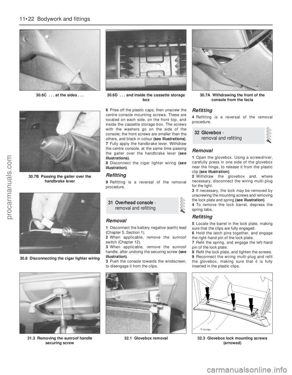
6Prise off the plastic caps, then unscrew the
centre console mounting screws. These are
located on each side, on the front top, and
inside the cassette storage box. The screws
with the washers go on the side of the
console; the front screws are smaller than the
others, and black in colour (see illustrations).
7Fully apply the handbrake lever. Withdraw
the centre console, at the same time passing
the gaiter over the handbrake lever (see
illustrations).
8Disconnect the cigar lighter wiring (see
illustration).
Refitting
9Refitting is a reversal of the removal
procedure.
Removal
1Disconnect the battery negative (earth) lead
(Chapter 5, Section 1).
2When applicable, remove the sunroof
switch (Chapter 12).
3When applicable, remove the sunroof
handle, after undoing the securing screw (see
illustration).
3Push the console towards the windscreen,
to disengage it from the clips.
Refitting
4Refitting is a reversal of the removal
procedure.
Removal
1Open the glovebox. Using a screwdriver,
carefully press in one side of the glovebox
near the hinge, to release it from the plastic
clip (see illustration).
2Withdraw the glovebox and, where
necessary, disconnect the wiring multi-plug
for the light.
3If necessary, the lock may be removed by
unscrewing the mounting screws and removing
the lock plate and spring (see illustration).
4To remove the lock barrel, depress the
spring tabs.
Refitting
5Locate the barrel in the lock plate, making
sure that the clips are fully engaged.
6Hold the latch pins together, and engage
the right-hand pin of the lock plate.
7Refit the spring, and engage the left-hand
pin of the lock plate.
8Refit the lock plate, and tighten the screws.
9Reconnect the wiring multi-plug and refit
the glovebox, making sure that it is fully
inserted in the plastic clips.
32 Glovebox -
removal and refitting
31 Overhead console -
removal and refitting
11•22 Bodywork and fittings
30.6C . . . at the sides . . .30.6D . . . and inside the cassette storage
box30.7A Withdrawing the front of the
console from the facia
31.3 Removing the sunroof handle
securing screw32.1 Glovebox removal
30.8 Disconnecting the cigar lighter wiring
30.7B Passing the gaiter over the
handbrake lever
32.3 Glovebox lock mounting screws
(arrowed)
procarmanuals.com