seat adjustment FORD MONDEO 1993 Service Repair Manual
[x] Cancel search | Manufacturer: FORD, Model Year: 1993, Model line: MONDEO, Model: FORD MONDEO 1993Pages: 279, PDF Size: 12.71 MB
Page 7 of 279
0•7
This is a guide to getting your vehicle through the MOT test.
Obviously it will not be possible to examine the vehicle to the same
standard as the professional MOT tester. However, working through
the following checks will enable you to identify any problem areas
before submitting the vehicle for the test.
Where a testable component is in borderline condition, the tester
has discretion in deciding whether to pass or fail it. The basis of such
discretion is whether the tester would be happy for a close relative or
friend to use the vehicle with the component in that condition. If the
vehicle presented is clean and evidently well cared for, the tester may
be more inclined to pass a borderline component than if the vehicle is
scruffy and apparently neglected.
It has only been possible to summarise the test requirements here,
based on the regulations in force at the time of printing. Test standards
are becoming increasingly stringent, although there are some
exemptions for older vehicles. For full details obtain a copy of the Haynes
publication Pass the MOT! (available from stockists of Haynes manuals).
An assistant will be needed to help carry out some of these checks.
The checks have been sub-divided into four categories, as follows:
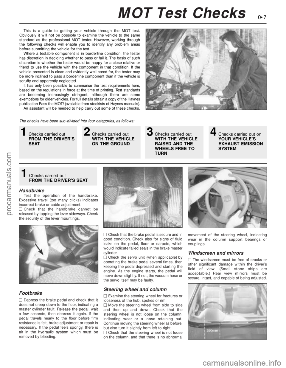
HandbrakeMTest the operation of the handbrake.
Excessive travel (too many clicks) indicates
incorrect brake or cable adjustment.
MCheck that the handbrake cannot be
released by tapping the lever sideways. Check
the security of the lever mountings.
Footbrake
MDepress the brake pedal and check that it
does not creep down to the floor, indicating a
master cylinder fault. Release the pedal, wait
a few seconds, then depress it again. If the
pedal travels nearly to the floor before firm
resistance is felt, brake adjustment or repair is
necessary. If the pedal feels spongy, there is
air in the hydraulic system which must be
removed by bleeding.MCheck that the brake pedal is secure and in
good condition. Check also for signs of fluid
leaks on the pedal, floor or carpets, which
would indicate failed seals in the brake master
cylinder.
MCheck the servo unit (when applicable) by
operating the brake pedal several times, then
keeping the pedal depressed and starting the
engine. As the engine starts, the pedal will
move down slightly. If not, the vacuum hose or
the servo itself may be faulty.
Steering wheel and column
MExamine the steering wheel for fractures or
looseness of the hub, spokes or rim.
MMove the steering wheel from side to side
and then up and down. Check that the
steering wheel is not loose on the column,
indicating wear or a loose retaining nut.
Continue moving the steering wheel as before,
but also turn it slightly from left to right.
MCheck that the steering wheel is not loose
on the column, and that there is no abnormalmovement of the steering wheel, indicating
wear in the column support bearings or
couplings.
Windscreen and mirrors
MThe windscreen must be free of cracks or
other significant damage within the driver’s
field of view. (Small stone chips are
acceptable.) Rear view mirrors must be
secure, intact, and capable of being adjusted.
1Checks carried out
FROM THE DRIVER’S SEAT
MOT Test Checks
1Checks carried out
FROM THE DRIVER’S
SEAT2Checks carried out
WITH THE VEHICLE
ON THE GROUND3Checks carried out
WITH THE VEHICLE
RAISED AND THE
WHEELS FREE TO
TURN4Checks carried out on
YOUR VEHICLE’S
EXHAUST EMISSION
SYSTEM
procarmanuals.com
Page 15 of 279
Chapter 1 Routine maintenance and servicing
Air conditioning system check . . . . . . . . . . . . . . . . . . . . . . . . . . . . . 14
Air filter element renewal . . . . . . . . . . . . . . . . . . . . . . . . . . . . . . . . . . 29
Automatic transmission fluid level check . . . . . . . . . . . . . . . . . . . . . 7
Automatic transmission linkage lubrication . . . . . . . . . . . . . . . . . . . 18
Auxiliary drivebelt check and renewal . . . . . . . . . . . . . . . . . . . . . . . . 11
Battery check, maintenance and charging . . . . . . . . . . . . . . . . . . . . 9
Brake check . . . . . . . . . . . . . . . . . . . . . . . . . . . . . . . . . . . . . . . . . . . 23
Brake fluid renewal . . . . . . . . . . . . . . . . . . . . . . . . . . . . . . . . . . . . . . 34
Clutch pedal adjustment . . . . . . . . . . . . . . . . . . . . . . . . . . . . . . . . . . 17
Coolant renewal . . . . . . . . . . . . . . . . . . . . . . . . . . . . . . . . . . . . . . 2, 28
Door and bonnet check and lubrication . . . . . . . . . . . . . . . . . . . . . . 24
Driveshaft rubber gaiter and CV joint check . . . . . . . . . . . . . . . . . . . 20
Electrical system check . . . . . . . . . . . . . . . . . . . . . . . . . . . . . . . . . . . 8
Engine compartment wiring check . . . . . . . . . . . . . . . . . . . . . . . . . . 13
Engine oil and filter change . . . . . . . . . . . . . . . . . . . . . . . . . . . . . . . . 15
Exhaust system check . . . . . . . . . . . . . . . . . . . . . . . . . . . . . . . . . . . 21
Fluid level checks . . . . . . . . . . . . . . . . . . . . . . . . . . . . . . . . . . . . . . . 3
Fuel filter renewal . . . . . . . . . . . . . . . . . . . . . . . . . . . . . . . . . . . . . . . 33
Idle speed and mixture check and adjustment . . . . . . See Chapter 4Ignition timing check . . . . . . . . . . . . . . . . . . . . . . . . . . See Chapter 5
Introduction . . . . . . . . . . . . . . . . . . . . . . . . . . . . . . . . . . . . . . . . . . . . 1
Manual transmission oil level check . . . . . . . . . . . . . . . . . . . . . . . . . 16
Positive Crankcase Ventilation (PCV) system check
and filter cleaning . . . . . . . . . . . . . . . . . . . . . . . . . . . . . . . . . . . . . 30
Power steering fluid level check . . . . . . . . . . . . . . . . . . . . . . . . . . . . 5
Road test . . . . . . . . . . . . . . . . . . . . . . . . . . . . . . . . . . . . . . . . . . . . . . 26
Roadwheel nut tightness check . . . . . . . . . . . . . . . . . . . . . . . . . . . . 25
Seat belt check . . . . . . . . . . . . . . . . . . . . . . . . . . . . . . . . . . . . . . . . . 10
Spark plug renewal . . . . . . . . . . . . . . . . . . . . . . . . . . . . . . . . . . . . . . 31
Specifications . . . . . . . . . . . . . . . . . . . . . . . . . . . . See end of Chapter
Steering, suspension and roadwheel check . . . . . . . . . . . . . . . . . . . 19
Timing belt renewal . . . . . . . . . . . . . . . . . . . . . . . . . . . . . . . . . . . . . . 32
Tyre and tyre pressure checks . . . . . . . . . . . . . . . . . . . . . . . . . . . . . 4
Underbody and fuel/brake line check . . . . . . . . . . . . . . . . . . . . . . . . 22
Underbonnet check for fluid leaks and hose condition . . . . . . . . . . 12
Ventilation system pollen filter renewal . . . . . . . . . . . . . . . . . . . . . . . 27
Windscreen/tailgate washer system and wiper blade check . . . . . . 6
1•1
Easy,suitable for
novice with little
experienceFairly easy,suitable
for beginner with
some experienceFairly difficult,suitable
for competent DIY
mechanicDifficult,suitable for
experienced DIY
mechanicVery difficult,
suitable for expert DIY
or professional
Degrees of difficulty Contents
1
procarmanuals.com
Page 17 of 279
Ford Mondeo maintenance schedule
1•3
1
Maintenance schedule
The manufacturer’s recommended maintenance schedule for these
vehicles is as described below - note that the schedule starts from the
vehicle’s date of registration. These are the minimum maintenance
intervals recommended by the factory for Mondeos driven daily, but
subjected only to “normal” use. If you wish to keep your vehicle in
peak condition at all times, you may wish to perform some of these
procedures even more often. Because frequent maintenance
enhances the efficiency, performance and resale value of your vehicle,
we encourage you to do so. If your usage is not “normal”, shorter
intervals are also recommended - the most important examples of
these are noted in the schedule. These shorter intervals apply
particularly if you drive in dusty areas, tow a caravan or trailer, sit with
the engine idling or drive at low speeds for extended periods (ie, in
heavy traffic), or drive for short distances (less than four miles) in
below-freezing temperatures.
When your vehicle is new, it should be serviced by a Ford dealer
service department to protect the factory warranty. In many cases, the
initial maintenance check is done at no cost to the owner. Note that
this first free service (carried out by the selling dealer 1500 miles or 3
months after delivery), although an important check for a new vehicle,
is not part of the regular maintenance schedule, and is therefore not
mentioned here.
Weekly checks
m mCheck the engine oil level, and top-up if necessary
(Section 3)
m mCheck the brake fluid level, and top-up if necessary
(Section 3). If repeated topping-up is required, check the
system for leaks or damage at the earliest possible
opportunity (Sections 12 and 22)
m mCheck the windscreen/tailgate washer fluid level, and top-
up if necessary (Section 3)
m mCheck the tyre pressures, including the spare (Section 4)
m mVisually check the tyres for excessive tread wear, or
damage (Section 4)
m mCheck the operation of all (exterior and interior) lights and
the horn, wipers and windscreen/tailgate washer system
(Sections 6 and 8). Renew any blown bulbs (Chapter 12),
and clean the lenses of all exterior lights
Monthly checks
m mCheck the coolant level, and top-up if necessary (Sec-
tion 3)
m mCheck the battery electrolyte level, where applicable
(Section 3)
m mCheck the power steering fluid level, and top-up if
necessary (Section 5)
m mVisually check all reservoirs, hoses and pipes for leakage
(Section 12)
m mCheck the operation of the air conditioning system
(Section 14)
m mCheck the operation of the handbrake (Section 23)
m mCheck the aim of the windscreen/tailgate/headlight
washer jets, correcting them if required (Section 6)
m mCheck the condition of the wiper blades, renewing them if
worn or no longer effective - note that the manufacturer
recommends renewing the blades as a safety precaution,
irrespective of their apparent condition, at least once a
year (Section 6)
Every 10 000 miles or 12 months,
whichever occurs first
Note:If the vehicle is used regularly for very short (less than
10 miles), stop/go journeys, the oil and filter should be renewed
between services (ie, every 5000 miles/6 months).
m mCheck the electrical system (Section 8)
m mCheck the battery (Section 9)
m mCheck the seat belts (Section 10)
m mCheck the auxiliary drivebelt (Section 11)
m mCheck for fluid leaks and hose condition (Section 12)
m mCheck the condition of all wiring (Section 13)
m mCheck all air conditioning components (Section 14)
m mChange the engine oil and filter (Section 15)
m mCheck the manual transmission oil level (Section 16)
m mCheck the adjustment of the clutch pedal (Section 17)
m mLubricate the automatic transmission linkage (Section 18)
m mCheck the steering, suspension and wheels (Section 19)
m mCheck the driveshaft gaiters and CV joints (Section 20)
m mCheck the exhaust system (Section 21)
m mCheck the underbody, and all fuel/brake lines (Section 22)
m mCheck the brake system (Section 23)
m mCheck and lubricate the doors and bonnet (Section 24)
m mCheck the security of all roadwheel nuts (Section 25)
m mRoad test (Section 26). Check the level of the automatic
transmission fluid with the engine still hot, after the road
test (Section 7)
Every 20 000 miles or 2 years,
whichever occurs first
Carry out all operations listed above, plus the following:
m mRenew the ventilation system pollen filter (Section 27)
m mRenew the coolant (Sections 2 and 28)
Every 30 000 miles or 3 years,
whichever occurs first
Carry out all operations listed above, plus the following:
m mRenew the air filter element (Section 29). Note that this
task must be carried out at more frequent intervals if the
vehicle is used in dusty or polluted conditions
m mCheck the Positive Crankcase Ventilation (PCV) system,
and clean the filter (Section 30)
m mRenew the spark plugs (Section 31)
Every 60 000 miles
Carry out all operations listed above, plus the following:
m
mRenew the timing belt (Section 32)
m mRenew the fuel filter (Section 33)
Every 3 years
(regardless of mileage)
m mRenew the brake fluid (Section 34)
procarmanuals.com
Page 27 of 279
amperage charger, but don’t use one rated
more than 1/10th the amp/hour rating of the
battery (ie no more than 5 amps, typically).
Rapid boost charges that claim to restore the
power of the battery in one to two hours are
hardest on the battery, and can damage
batteries not in good condition. This type of
charging should only be used in emergency
situations.
14The average time necessary to charge a
battery should be listed in the instructions that
come with the charger. As a general rule, a
trickle charger will charge a battery in 12 to
16 hours.
1Check the seat belts for satisfactory
operation and condition. Inspect the webbing
for fraying and cuts. Check that they retract
smoothly and without binding into their reels.
2Check that the seat belt mounting bolts are
tight, and if necessary tighten them to the
specified torque wrench setting.
General
1The auxiliary drivebelt is of the flat, multi-
ribbed (or “polyvee”) type, and is located on
the right-hand end of the engine. It drives the
alternator, water pump, power steering pump
and (when fitted) the air conditioning
compressor from the engine’s crankshaft
pulley.
2The good condition and proper tension of
the auxiliary drivebelt is critical to the
operation of the engine. Because of their
composition and the high stresses to which
they are subjected, drivebelts stretch anddeteriorate as they get older. They must,
therefore, be regularly inspected.
Check
3With the engine switched off, open and
support the bonnet, then locate the auxiliary
drivebelt on the right-hand end of the engine,
under the engine right-hand mounting
bracket. (Be very careful, and wear protective
gloves to minimise the risk of burning your
hands on hot components, if the engine has
recently been running.) For improved access,
jack up the front right-hand side of the
vehicle, support it securely on an axle stand,
remove the roadwheel, then remove the
auxiliary drivebelt cover (two fasteners) from
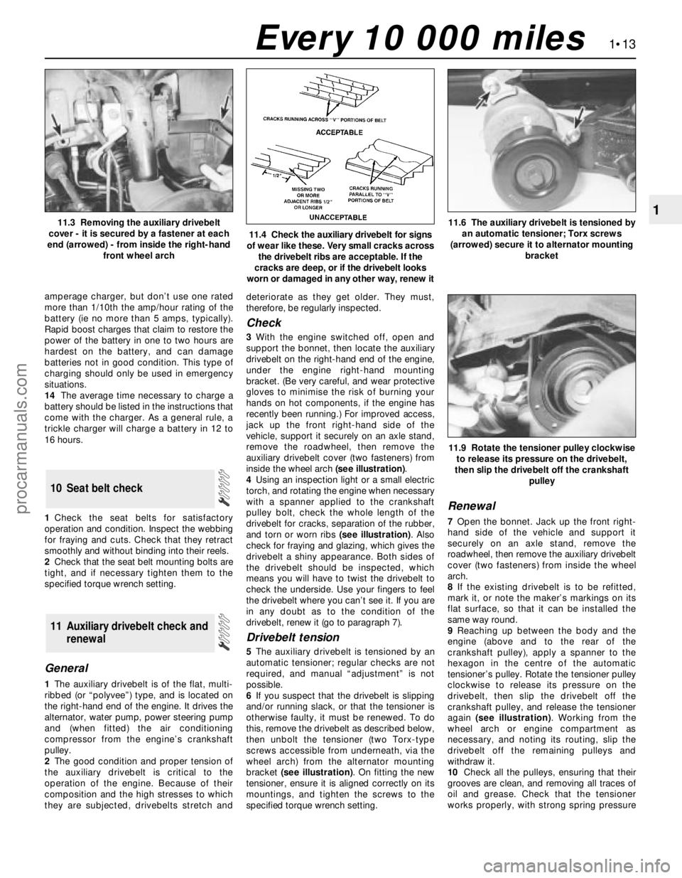
inside the wheel arch (see illustration).
4Using an inspection light or a small electric
torch, and rotating the engine when necessary
with a spanner applied to the crankshaft
pulley bolt, check the whole length of the
drivebelt for cracks, separation of the rubber,
and torn or worn ribs (see illustration). Also
check for fraying and glazing, which gives the
drivebelt a shiny appearance. Both sides of
the drivebelt should be inspected, which
means you will have to twist the drivebelt to
check the underside. Use your fingers to feel
the drivebelt where you can’t see it. If you are
in any doubt as to the condition of the
drivebelt, renew it (go to paragraph 7).
Drivebelt tension
5The auxiliary drivebelt is tensioned by an
automatic tensioner; regular checks are not
required, and manual “adjustment” is not
possible.
6If you suspect that the drivebelt is slipping
and/or running slack, or that the tensioner is
otherwise faulty, it must be renewed. To do
this, remove the drivebelt as described below,
then unbolt the tensioner (two Torx-type
screws accessible from underneath, via the
wheel arch) from the alternator mounting
bracket (see illustration). On fitting the new
tensioner, ensure it is aligned correctly on its
mountings, and tighten the screws to the
specified torque wrench setting.
Renewal
7Open the bonnet. Jack up the front right-
hand side of the vehicle and support it
securely on an axle stand, remove the
roadwheel, then remove the auxiliary drivebelt
cover (two fasteners) from inside the wheel
arch.
8If the existing drivebelt is to be refitted,
mark it, or note the maker’s markings on its
flat surface, so that it can be installed the
same way round.
9Reaching up between the body and the
engine (above and to the rear of the
crankshaft pulley), apply a spanner to the
hexagon in the centre of the automatic
tensioner’s pulley. Rotate the tensioner pulley
clockwise to release its pressure on the
drivebelt, then slip the drivebelt off the
crankshaft pulley, and release the tensioner
again (see illustration). Working from the
wheel arch or engine compartment as
necessary, and noting its routing, slip the
drivebelt off the remaining pulleys and
withdraw it.
10Check all the pulleys, ensuring that their
grooves are clean, and removing all traces of
oil and grease. Check that the tensioner
works properly, with strong spring pressure
11 Auxiliary drivebelt check and
renewal
10 Seat belt check
1•13
1
11.9 Rotate the tensioner pulley clockwise
to release its pressure on the drivebelt,
then slip the drivebelt off the crankshaft
pulley
11.3 Removing the auxiliary drivebelt
cover - it is secured by a fastener at each
end (arrowed) - from inside the right-hand
front wheel arch
11.4 Check the auxiliary drivebelt for signs
of wear like these. Very small cracks across
the drivebelt ribs are acceptable. If the
cracks are deep, or if the drivebelt looks
worn or damaged in any other way, renew it
11.6 The auxiliary drivebelt is tensioned by
an automatic tensioner; Torx screws
(arrowed) secure it to alternator mounting
bracket
Every 10 000 miles
procarmanuals.com
Page 31 of 279
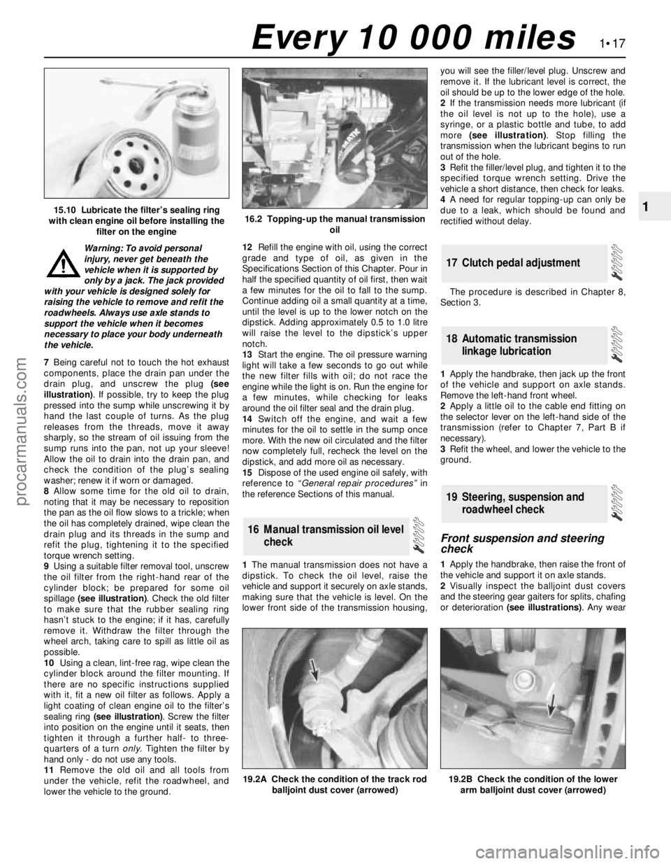
Warning: To avoid personal
injury, never get beneath the
vehicle when it is supported by
only by a jack. The jack provided
with your vehicle is designed solely for
raising the vehicle to remove and refit the
roadwheels. Always use axle stands to
support the vehicle when it becomes
necessary to place your body underneath
the vehicle.
7Being careful not to touch the hot exhaust
components, place the drain pan under the
drain plug, and unscrew the plug (see
illustration). If possible, try to keep the plug
pressed into the sump while unscrewing it by
hand the last couple of turns. As the plug
releases from the threads, move it away
sharply, so the stream of oil issuing from the
sump runs into the pan, not up your sleeve!
Allow the oil to drain into the drain pan, and
check the condition of the plug’s sealing
washer; renew it if worn or damaged.
8Allow some time for the old oil to drain,
noting that it may be necessary to reposition
the pan as the oil flow slows to a trickle; when
the oil has completely drained, wipe clean the
drain plug and its threads in the sump and
refit the plug, tightening it to the specified
torque wrench setting.
9Using a suitable filter removal tool, unscrew
the oil filter from the right-hand rear of the
cylinder block; be prepared for some oil
spillage (see illustration). Check the old filter
to make sure that the rubber sealing ring
hasn’t stuck to the engine; if it has, carefully
remove it. Withdraw the filter through the
wheel arch, taking care to spill as little oil as
possible.
10Using a clean, lint-free rag, wipe clean the
cylinder block around the filter mounting. If
there are no specific instructions supplied
with it, fit a new oil filter as follows. Apply a
light coating of clean engine oil to the filter’s
sealing ring (see illustration). Screw the filter
into position on the engine until it seats, then
tighten it through a further half- to three-
quarters of a turn only. Tighten the filter by
hand only - do not use any tools.
11Remove the old oil and all tools from
under the vehicle, refit the roadwheel, and
lower the vehicle to the ground.12Refill the engine with oil, using the correct
grade and type of oil, as given in the
Specifications Section of this Chapter. Pour in
half the specified quantity of oil first, then wait
a few minutes for the oil to fall to the sump.
Continue adding oil a small quantity at a time,
until the level is up to the lower notch on the
dipstick. Adding approximately 0.5 to 1.0 litre
will raise the level to the dipstick’s upper
notch.
13Start the engine. The oil pressure warning
light will take a few seconds to go out while
the new filter fills with oil; do not race the
engine while the light is on. Run the engine for
a few minutes, while checking for leaks
around the oil filter seal and the drain plug.
14Switch off the engine, and wait a few
minutes for the oil to settle in the sump once
more. With the new oil circulated and the filter
now completely full, recheck the level on the
dipstick, and add more oil as necessary.
15Dispose of the used engine oil safely, with
reference to “General repair procedures”in
the reference Sections of this manual.
1The manual transmission does not have a
dipstick. To check the oil level, raise the
vehicle and support it securely on axle stands,
making sure that the vehicle is level. On the
lower front side of the transmission housing,you will see the filler/level plug. Unscrew and
remove it. If the lubricant level is correct, the
oil should be up to the lower edge of the hole.
2If the transmission needs more lubricant (if
the oil level is not up to the hole), use a
syringe, or a plastic bottle and tube, to add
more (see illustration). Stop filling the
transmission when the lubricant begins to run
out of the hole.
3Refit the filler/level plug, and tighten it to the
specified torque wrench setting. Drive the
vehicle a short distance, then check for leaks.
4A need for regular topping-up can only be
due to a leak, which should be found and
rectified without delay.
The procedure is described in Chapter 8,
Section 3.
1Apply the handbrake, then jack up the front
of the vehicle and support on axle stands.
Remove the left-hand front wheel.
2Apply a little oil to the cable end fitting on
the selector lever on the left-hand side of the
transmission (refer to Chapter 7, Part B if
necessary).
3Refit the wheel, and lower the vehicle to the
ground.
Front suspension and steering
check
1Apply the handbrake, then raise the front of
the vehicle and support it on axle stands.
2Visually inspect the balljoint dust covers
and the steering gear gaiters for splits, chafing
or deterioration (see illustrations). Any wear
19 Steering, suspension and
roadwheel check
18 Automatic transmission
linkage lubrication
17 Clutch pedal adjustment
16 Manual transmission oil level
check
1•17
1
19.2B Check the condition of the lower
arm balljoint dust cover (arrowed)
15.10 Lubricate the filter’s sealing ring
with clean engine oil before installing the
filter on the engine16.2 Topping-up the manual transmission
oil
19.2A Check the condition of the track rod
balljoint dust cover (arrowed)
Every 10 000 miles
procarmanuals.com
Page 39 of 279
check the cylinder head threads and tapered
sealing surfaces for signs of wear, excessive
corrosion or damage; if any of these
conditions is found, seek the advice of a Ford
dealer as to the best method of repair.
7As each plug is removed, examine it as
follows - this will give a good indication of the
condition of the engine. If the insulator nose of
the spark plug is clean and white, with no
deposits, this is indicative of a weak mixture.
8If the tip and insulator nose are covered
with hard black-looking deposits, then this is
indicative that the mixture is too rich. Should
the plug be black and oily, then it is likely that
the engine is fairly worn, as well as the mixture
being too rich.
9If the insulator nose is covered with light tan
to greyish-brown deposits, then the mixture is
correct, and it is likely that the engine is in
good condition.
10If you are renewing the spark plugs,
purchase the new plugs, then check each of
them first for faults such as cracked insulators
or damaged threads. Note also that,
whenever the spark plugs are renewed as a
routine service operation, the spark plug (HT)
leads should be checked as described below.
11The spark plug electrode gap is of
considerable importance as, if it is too large or
too small, the size of the spark and its
efficiency will be seriously impaired. The gap
should be set to the value given in the
Specifications Section of this Chapter. New
plugs will not necessarily be set to the correct
gap, so they should always be checked
before fitting.
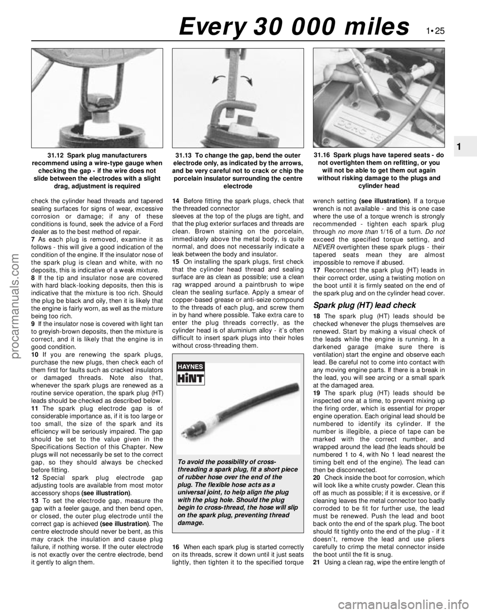
12Special spark plug electrode gap
adjusting tools are available from most motor
accessory shops (see illustration).
13To set the electrode gap, measure the
gap with a feeler gauge, and then bend open,
or closed, the outer plug electrode until the
correct gap is achieved (see illustration). The
centre electrode should never be bent, as this
may crack the insulation and cause plug
failure, if nothing worse. If the outer electrode
is not exactly over the centre electrode, bend
it gently to align them.14Before fitting the spark plugs, check that
the threaded connector
sleeves at the top of the plugs are tight, and
that the plug exterior surfaces and threads are
clean. Brown staining on the porcelain,
immediately above the metal body, is quite
normal, and does not necessarily indicate a
leak between the body and insulator.
15On installing the spark plugs, first check
that the cylinder head thread and sealing
surface are as clean as possible; use a clean
rag wrapped around a paintbrush to wipe
clean the sealing surface. Apply a smear of
copper-based grease or anti-seize compound
to the threads of each plug, and screw them
in by hand where possible. Take extra care to
enter the plug threads correctly, as the
cylinder head is of aluminium alloy - it’s often
difficult to insert spark plugs into their holes
without cross-threading them.
16When each spark plug is started correctly
on its threads, screw it down until it just seats
lightly, then tighten it to the specified torquewrench setting (see illustration). If a torque
wrench is not available - and this is one case
where the use of a torque wrench is strongly
recommended - tighten each spark plug
through no more than1/16 of a turn. Do not
exceed the specified torque setting, and
NEVERovertighten these spark plugs - their
tapered seats mean they are almost
impossible to remove if abused.
17Reconnect the spark plug (HT) leads in
their correct order, using a twisting motion on
the boot until it is firmly seated on the end of
the spark plug and on the cylinder head cover.
Spark plug (HT) lead check
18The spark plug (HT) leads should be
checked whenever the plugs themselves are
renewed. Start by making a visual check of
the leads while the engine is running. In a
darkened garage (make sure there is
ventilation) start the engine and observe each
lead. Be careful not to come into contact with
any moving engine parts. If there is a break in
the lead, you will see arcing or a small spark
at the damaged area.
19The spark plug (HT) leads should be
inspected one at a time, to prevent mixing up
the firing order, which is essential for proper
engine operation. Each original lead should be
numbered to identify its cylinder. If the
number is illegible, a piece of tape can be
marked with the correct number, and
wrapped around the lead (the leads should be
numbered 1 to 4, with No 1 lead nearest the
timing belt end of the engine). The lead can
then be disconnected.
20Check inside the boot for corrosion, which
will look like a white crusty powder. Clean this
off as much as possible; if it is excessive, or if
cleaning leaves the metal connector too badly
corroded to be fit for further use, the lead
must be renewed. Push the lead and boot
back onto the end of the spark plug. The boot
should fit tightly onto the end of the plug - if it
doesn’t, remove the lead and use pliers
carefully to crimp the metal connector inside
the boot until the fit is snug.
21Using a clean rag, wipe the entire length of
1•25
1
Every 30 000 miles
31.12 Spark plug manufacturers
recommend using a wire-type gauge when
checking the gap - if the wire does not
slide between the electrodes with a slight
drag, adjustment is required31.13 To change the gap, bend the outer
electrode only, as indicated by the arrows,
and be very careful not to crack or chip the
porcelain insulator surrounding the centre
electrode31.16 Spark plugs have tapered seats - do
not overtighten them on refitting, or you
will not be able to get them out again
without risking damage to the plugs and
cylinder head
To avoid the possibility of cross-
threading a spark plug, fit a short piece
of rubber hose over the end of the
plug. The flexible hose acts as a
universal joint, to help align the plug
with the plug hole. Should the plug
begin to cross-thread, the hose will slip
on the spark plug, preventing thread
damage.
procarmanuals.com
Page 43 of 279
Torque wrench settings (continued)Nm lbf ft
Engine/automatic transmission rear mounting:
Mounting bracket-to-transmission . . . . . . . . . . . . . . . . . . . . . . . . . . . 48 to 49 35 to 36
Mounting-to-subframe bolts - stage 1 . . . . . . . . . . . . . . . . . . . . . . . . 10 7
Mounting-to-subframe bolts - stage 2 . . . . . . . . . . . . . . . . . . . . . . . . 48 35
Mounting centre bolt . . . . . . . . . . . . . . . . . . . . . . . . . . . . . . . . . . . . . . 120 89
Engine/transmission left-hand mounting:
Bracket-to-transmission nuts . . . . . . . . . . . . . . . . . . . . . . . . . . . . . . . 83 61
Mounting centre bolt . . . . . . . . . . . . . . . . . . . . . . . . . . . . . . . . . . . . . . Not available
Mounting-to-body bolts . . . . . . . . . . . . . . . . . . . . . . . . . . . . . . . . . . . Not available
Engine/transmission right-hand mounting:
Bracket-to-engine and mounting nuts . . . . . . . . . . . . . . . . . . . . . . . . 83 to 90 61 to 66
Mounting-to-body bolts . . . . . . . . . . . . . . . . . . . . . . . . . . . . . . . . . . . 84 62
Note:Refer to Part B of this Chapter for remaining torque wrench settings.
In-car engine repair procedures 2A•3
2A
How to use this Chapter
This Part of Chapter 2 is devoted to repair
procedures possible while the engine is still
installed in the vehicle, and includes only the
Specifications relevant to those procedures.
Since these procedures are based on the
assumption that the engine is installed in the
vehicle, if the engine has been removed from
the vehicle and mounted on a stand, some of
the preliminary dismantling steps outlined will
not apply.
Information concerning engine/transmission
removal and refitting, and engine overhaul, can
be found in Part B of this Chapter, which also
includes the Specifications relevant to those
procedures.
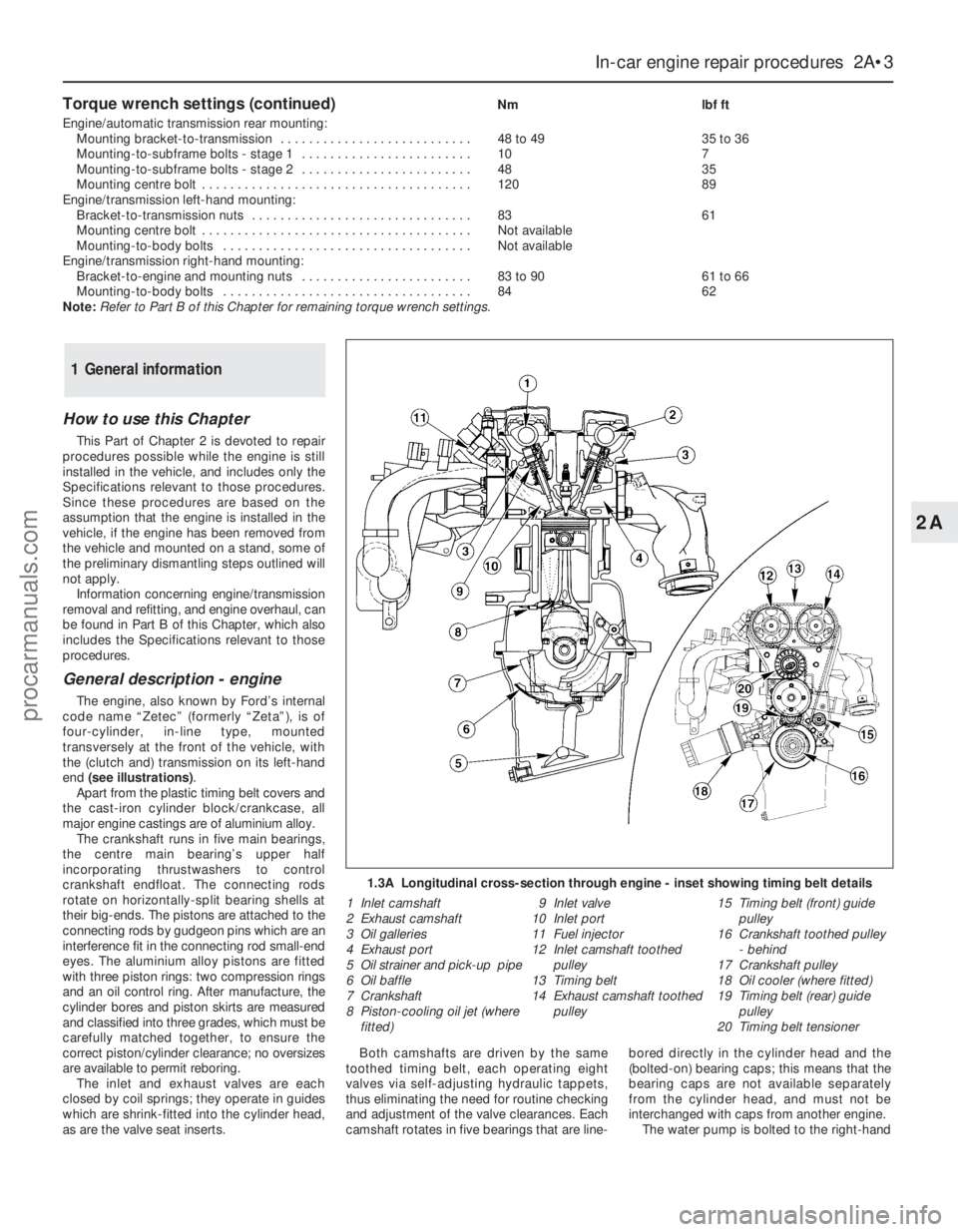
General description - engine
The engine, also known by Ford’s internal
code name “Zetec” (formerly “Zeta”), is of
four-cylinder, in-line type, mounted
transversely at the front of the vehicle, with
the (clutch and) transmission on its left-hand
end (see illustrations).
Apart from the plastic timing belt covers and
the cast-iron cylinder block/crankcase, all
major engine castings are of aluminium alloy.
The crankshaft runs in five main bearings,
the centre main bearing’s upper half
incorporating thrustwashers to control
crankshaft endfloat. The connecting rods
rotate on horizontally-split bearing shells at
their big-ends. The pistons are attached to the
connecting rods by gudgeon pins which are an
interference fit in the connecting rod small-end
eyes. The aluminium alloy pistons are fitted
with three piston rings: two compression rings
and an oil control ring. After manufacture, the
cylinder bores and piston skirts are measured
and classified into three grades, which must be
carefully matched together, to ensure the
correct piston/cylinder clearance; no oversizes
are available to permit reboring.
The inlet and exhaust valves are each
closed by coil springs; they operate in guides
which are shrink-fitted into the cylinder head,
as are the valve seat inserts.Both camshafts are driven by the same
toothed timing belt, each operating eight
valves via self-adjusting hydraulic tappets,
thus eliminating the need for routine checking
and adjustment of the valve clearances. Each
camshaft rotates in five bearings that are line-bored directly in the cylinder head and the
(bolted-on) bearing caps; this means that the
bearing caps are not available separately
from the cylinder head, and must not be
interchanged with caps from another engine.
The water pump is bolted to the right-hand
1 General information
1.3A Longitudinal cross-section through engine - inset showing timing belt details
1 Inlet camshaft
2 Exhaust camshaft
3 Oil galleries
4 Exhaust port
5 Oil strainer and pick-up pipe
6 Oil baffle
7 Crankshaft
8 Piston-cooling oil jet (where
fitted)9 Inlet valve
10 Inlet port
11 Fuel injector
12 Inlet camshaft toothed
pulley
13 Timing belt
14 Exhaust camshaft toothed
pulley15 Timing belt (front) guide
pulley
16 Crankshaft toothed pulley
- behind
17 Crankshaft pulley
18 Oil cooler (where fitted)
19 Timing belt (rear) guide
pulley
20 Timing belt tensioner
procarmanuals.com
Page 45 of 279
The cylinder head is provided with two oil
galleries, one on the inlet side and one on the
exhaust, to ensure constant oil supply to the
camshaft bearings and hydraulic tappets. A
retaining valve (inserted into the cylinder
head’s top surface, in the middle, on the inlet
side) prevents these galleries from being
drained when the engine is switched off. The
valve incorporates a ventilation hole in its
upper end, to allow air bubbles to escape
from the system when the engine is restarted.
While the crankshaft and camshaft
bearings and the hydraulic tappets receive a
pressurised supply, the camshaft lobes and
valves are lubricated by splash, as are all
other engine components.
Valve clearances - general
It is necessary for a clearance to exist
between the tip of each valve stem and the
valve operating mechanism, to allow for the
expansion of the various components as the
engine reaches normal operating
temperature.
On most older engine designs, this meant
that the valve clearances (also known as
“tappet” clearances) had to be checked and
adjusted regularly. If the clearances were
allowed to be too slack, the engine would be
very noisy, its power output would suffer, and
its fuel consumption would increase. If the
clearances were allowed to be too tight, the
engine’s power output would be reduced,
and the valves and their seats could be
severely damaged.
The engines covered in this manual,
however, employ hydraulic tappets which use
the lubricating system’s oil pressure
automatically to take up the clearance
between each camshaft lobe and its
respective valve stem. Therefore, there is no
need for regular checking and adjustment of
the valve clearances, but it is essential that
onlygood-quality oil of the recommended
viscosity and specification is used in the
engine, and that this oil is always changed at
the recommended intervals. If this advice is
not followed, the oilways and tappets may
become clogged with particles of dirt, or
deposits of burnt (inferior) engine oil, so that
the system cannot work properly; ultimately,
one or more of the tappets may fail, and
expensive repairs may be required.
On starting the engine from cold, there will
be a slight delay while full oil pressure builds
up in all parts of the engine, especially in the
tappets; the valve components, therefore,
may well “rattle” for about 10 seconds or so,
and then quieten. This is a normal state of
affairs, and is nothing to worry about,
provided that all tappets quieten quickly and
stay quiet.
After the vehicle has been standing for
several days, the valve components may
“rattle” for longer than usual, as nearly all the
oil will have drained away from the engine’s
top end components and bearing surfaces.
While this is only to be expected, care mustbe taken not to damage the engine under
these circumstances - avoid high speed
running until all the tappets are refilled with oil
and operating normally. With the vehicle
stationary, hold the engine at no more than a
fast idle speed (maximum 2000 to 2500 rpm)
for 10 to 15 seconds, or until the noise
ceases. Do not run the engine at more than
3000 rpm until the tappets are fully recharged
with oil and the noise has ceased.
If the valve components are thought to be
noisy, or if a light rattle persists from the top
end after the engine has warmed up to
normal operating temperature, take the
vehicle to a Ford dealer for expert advice.
Depending on the mileage covered and the
usage to which each vehicle has been put,
some vehicles may be noisier than others;
only a good mechanic experienced in these
engines can tell if the noise level is typical for
the vehicle’s mileage, or if a genuine fault
exists. If any tappet’s operation is faulty, it
must be renewed (Section 13).
The following major repair operations can
be accomplished without removing the
engine from the vehicle. However, owners
should note that any operation involving the
removal of the sump requires careful
forethought, depending on the level of skill
and the tools and facilities available; refer to
the relevant text for details.
(a) Compression pressure - testing.
(b) Cylinder head cover - removal and
refitting.
(c) Timing belt covers - removal and refitting.
(d) Timing belt - renewal.
(e) Timing belt tensioner and toothed pulleys
- removal and refitting.
(f) Camshaft oil seals - renewal.
(g) Camshafts and hydraulic tappets -
removal and refitting.
(h) Cylinder head - removal, overhaul and
refitting.
(i) Cylinder head and pistons -
decarbonising.
(j) Sump - removal and refitting.
(k) Crankshaft oil seals - renewal.
(l) Oil pump - removal and refitting.
(m) Piston/connecting rod assemblies -
removal and refitting (but see note below).
(n) Flywheel/driveplate - removal and
refitting.
(o) Engine/transmission mountings - removal
and refitting.
Clean the engine compartment and the
exterior of the engine with some type of
degreaser before any work is done. It will
make the job easier, and will help to keep dirt
out of the internal areas of the engine.
Depending on the components involved, it
may be helpful to remove the bonnet, to
improve access to the engine as repairs are
performed (refer to Chapter 11 if necessary).Cover the wings to prevent damage to the
paint; special covers are available, but an old
bedspread or blanket will also work.
If vacuum, exhaust, oil or coolant leaks
develop, indicating a need for component/
gasket or seal replacement, the repairs can
generally be made with the engine in the
vehicle. The intake and exhaust manifold
gaskets, sump gasket, crankshaft oil seals
and cylinder head gasket are all accessible
with the engine in place.
Exterior components such as the intake
and exhaust manifolds, the sump, the oil
pump, the water pump, the starter motor, the
alternator and the fuel system components
can be removed for repair with the engine in
place.
Since the cylinder head can be removed
without lifting out the engine, camshaft and
valve component servicing can also be
accomplished with the engine in the vehicle,
as can renewal of the timing belt and toothed
pulleys.
In extreme cases caused by a lack of
necessary equipment, repair or renewal of
piston rings, pistons, connecting rods and
big-end bearings is possible with the engine
in the vehicle. However, this practice is not
recommended, because of the cleaning and
preparation work that must be done to the
components involved, and because of the
amount of preliminary dismantling work
required - these operations are therefore
covered in Part B of this Chapter.
1When engine performance is down, or if
misfiring occurs which cannot be attributed to
the ignition or fuel systems, a compression
test can provide diagnostic clues as to the
engine’s condition. If the test is performed
regularly, it can give warning of trouble before
any other symptoms become apparent.
2The engine must be fully warmed-up to
normal operating temperature, the oil level
must be correct, the battery must be fully
charged, and the spark plugs must be
removed. The aid of an assistant will be
required also.
3Disable the ignition system by unplugging
the ignition coil’s electrical connector, and
remove fuse 14 to disconnect the fuel pump.
4Fit a compression tester to the No 1
cylinder spark plug hole - the type of tester
which screws into the plug thread is to be
preferred.
5Have the assistant hold the throttle wide
open and crank the engine on the starter
motor; after one or two revolutions, the
compression pressure should build up to a
maximum figure, and then stabilise. Record
the highest reading obtained.
6Repeat the test on the remaining cylinders,
recording the pressure developed in each.
7At the time of writing, no compression
3 Compression test -
description and interpretation
2 Repair operations possible with
the engine in the vehicle
In-car engine repair procedures 2A•5
2A
procarmanuals.com
Page 75 of 279
gear linkage heat shield. Reconnect the
gearchange linkage and transmission support
rods to the transmission, adjusting the linkage
using the marks made on removal (see
Chapter 7, Part A, for details).
56Re-install the remaining components and
fasteners in the reverse order of removal.
57Add coolant, engine oil and transmission
fluids as needed (see Chapter 1).
58Run the engine, and check for proper
operation and the absence of leaks. Shut off
the engine, and recheck the fluid levels.
59Remember that, since the front suspension
subframe and steering gear have been
disturbed, the wheel alignment and steering
angles must be checked fully and carefully as
soon as possible, with any necessary
adjustments being made. This operation is best
carried out by an experienced mechanic, using
proper checking equipment; the vehicle should
therefore be taken to a Ford dealer or similarly-
qualified person for attention.
1It is much easier to dismantle and work on
the engine if it is mounted on a portable engine
stand. These stands can often be hired from a
tool hire shop. Before the engine is mounted
on a stand, the flywheel/driveplate should be
removed (Part A of this Chapter, Section 21)
so that the stand bolts can be tightened into
the end of the cylinder block/crankcase.
2If a stand is not available, it is possible to
dismantle the engine with it mounted on
blocks, on a sturdy workbench or on the floor.
Be extra-careful not to tip or drop the engine
when working without a stand.
3If you are going to obtain a reconditioned
engine, all external components must be
removed first, to be transferred to the
replacement engine (just as they will if you are
doing a complete engine overhaul yourself).
Note:When removing the external
components from the engine, pay close
attention to details that may be helpful or
important during refitting. Note the fitted
position of gaskets, seals, spacers, pins,
washers, bolts and other small items.These
external components include the following:
(a) Alternator and brackets (Chapter 5).
(b) HT leads and spark plugs (Chapter 1).
(c) Thermostat and housing (Chapter 3).
(d) Dipstick tube.
(e) Fuel injection system components
(Chapter 4).
(f) All electrical switches and sensors - refer
to the appropriate Chapter.
(g) Inlet and exhaust manifolds (Part A of this
Chapter).
(h) Oil filter (Chapter 1).
(i) Engine/transmission mounting brackets
(Part A of this Chapter, Section 22).
(j) Flywheel/driveplate (Part A of this
Chapter, Section 21).
4If you are obtaining a “short” engine (whichconsists of the engine cylinder
block/crankcase, crankshaft, pistons and
connecting rods all assembled), then the
cylinder head, sump, oil pump, and timing belt
will have to be removed also.
5If you are planning a complete overhaul, the
engine can be dismantled and the internal
components removed in the following order.
(a) Inlet and exhaust manifolds (Part A of this
Chapter).
(b) Timing belt, toothed pulleys and
tensioner, and timing belt inner cover
(Part A of this Chapter).
(c) Cylinder head (Part A of this Chapter,
Section 14).
(d) Flywheel/driveplate (Part A of this
Chapter, Section 21).
(e) Sump (Part A of this Chapter, Section 15).
(f) Oil pump (Part A of this Chapter, Sec-
tion 16).
(g) Piston/connecting rod assemblies
(Section 9).
(h) Crankshaft (Section 10).
6Before beginning the dismantling andoverhaul procedures, make sure that you have
all of the correct tools necessary. Refer to the
introductory pages at the beginning of this
manual for further information.
Note:New and reconditioned cylinder heads
are available from the manufacturers, and
from engine overhaul specialists. Due to the
fact that some specialist tools are required for
the dismantling and inspection procedures,
and new components may not be readily
available (refer to Section 1 of this Part), it may
be more practical and economical for the
home mechanic to purchase a reconditioned
head, rather than to dismantle, inspect and
recondition the original head.
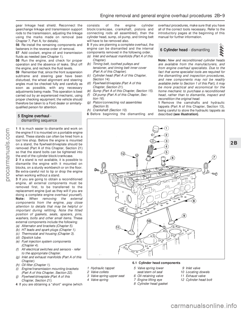
1Remove the camshafts and hydraulic
tappets (Part A of this Chapter, Section 13),
being careful to store the hydraulic tappets as
described (see illustration).
6 Cylinder head - dismantling
5 Engine overhaul-
dismantling sequence
Engine removal and general engine overhaul procedures 2B•9
2B
6.1 Cylinder head components
1 Hydraulic tappet
2 Valve collets
3 Valve spring upper seat
4 Valve spring5 Valve spring lower
seat/stem oil seal
6 Oil-retaining valve
7 Engine lifting eye
8 Cylinder head gasket9 Inlet valve
10 Locating dowels
11 Exhaust valve
12 Cylinder head bolt
procarmanuals.com
Page 102 of 279
housing stud) and the sealing O-ring in the
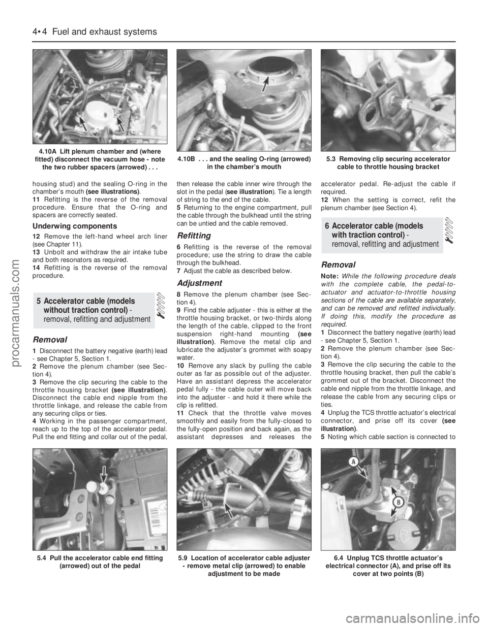
chamber’s mouth (see illustrations).
11Refitting is the reverse of the removal
procedure. Ensure that the O-ring and
spacers are correctly seated.
Underwing components
12Remove the left-hand wheel arch liner
(see Chapter 11).
13Unbolt and withdraw the air intake tube
and both resonators as required.
14Refitting is the reverse of the removal
procedure.
Removal
1Disconnect the battery negative (earth) lead
- see Chapter 5, Section 1.
2Remove the plenum chamber (see Sec-
tion 4).
3Remove the clip securing the cable to the
throttle housing bracket (see illustration).
Disconnect the cable end nipple from the
throttle linkage, and release the cable from
any securing clips or ties.
4Working in the passenger compartment,
reach up to the top of the accelerator pedal.
Pull the end fitting and collar out of the pedal,then release the cable inner wire through the
slot in the pedal (see illustration). Tie a length
of string to the end of the cable.
5Returning to the engine compartment, pull
the cable through the bulkhead until the string
can be untied and the cable removed.
Refitting
6Refitting is the reverse of the removal
procedure; use the string to draw the cable
through the bulkhead.
7Adjust the cable as described below.
Adjustment
8Remove the plenum chamber (see Sec-
tion 4).
9Find the cable adjuster - this is either at the
throttle housing bracket, or two-thirds along
the length of the cable, clipped to the front
suspension right-hand mounting (see
illustration). Remove the metal clip and
lubricate the adjuster’s grommet with soapy
water.
10Remove any slack by pulling the cable
outer as far as possible out of the adjuster.
Have an assistant depress the accelerator
pedal fully - the cable outer will move back
into the adjuster - and hold it there while the
clip is refitted.
11Check that the throttle valve moves
smoothly and easily from the fully-closed to
the fully-open position and back again, as the
assistant depresses and releases theaccelerator pedal. Re-adjust the cable if
required.
12When the setting is correct, refit the
plenum chamber (see Section 4).
Removal
Note:While the following procedure deals
with the complete cable, the pedal-to-
actuator and actuator-to-throttle housing
sections of the cable are available separately,
and can be removed and refitted individually.
If doing this, modify the procedure as
required.
1Disconnect the battery negative (earth) lead
- see Chapter 5, Section 1.
2Remove the plenum chamber (see Sec-
tion 4).
3Remove the clip securing the cable to the
throttle housing bracket, then pull the cable’s
grommet out of the bracket. Disconnect the
cable end nipple from the throttle linkage, and
release the cable from any securing clips or
ties.
4Unplug the TCS throttle actuator’s electrical
connector, and prise off its cover (see
illustration).
5Noting which cable section is connected to
6 Accelerator cable (models
with traction control)-
removal, refitting and adjustment
5 Accelerator cable (models
without traction control) -
removal, refitting and adjustment
4•4 Fuel and exhaust systems
4.10A Lift plenum chamber and (where
fitted) disconnect the vacuum hose - note
the two rubber spacers (arrowed) . . .4.10B . . . and the sealing O-ring (arrowed)
in the chamber’s mouth5.3 Removing clip securing accelerator
cable to throttle housing bracket
5.4 Pull the accelerator cable end fitting
(arrowed) out of the pedal5.9 Location of accelerator cable adjuster
- remove metal clip (arrowed) to enable
adjustment to be made6.4 Unplug TCS throttle actuator’s
electrical connector (A), and prise off its
cover at two points (B)
procarmanuals.com