02 sensor FORD POLICE INTERCEPTOR UTILITY 2016 1.G Owner's Manual
[x] Cancel search | Manufacturer: FORD, Model Year: 2016, Model line: POLICE INTERCEPTOR UTILITY, Model: FORD POLICE INTERCEPTOR UTILITY 2016 1.GPages: 350, PDF Size: 3.58 MB
Page 131 of 350
Main Menu
SettingsVehicle
Camera Settings
Enhanced Park Aids or Park Pilot
Selectable settings for this feature are ON
and OFF.
The system uses red, yellow and green
highlights that appear on top of the video
image when any of the sensing systems
detect an object.
Vehicles equipped with MyFord Touch ™
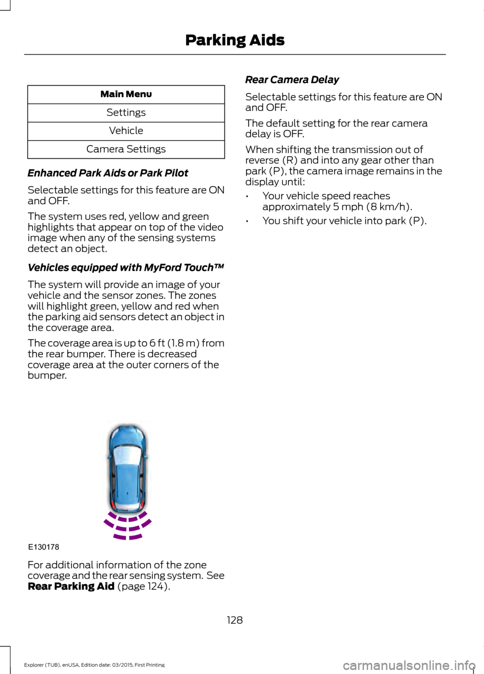
The system will provide an image of your
vehicle and the sensor zones. The zones
will highlight green, yellow and red when
the parking aid sensors detect an object in
the coverage area.
The coverage area is up to 6 ft (1.8 m) from
the rear bumper. There is decreased
coverage area at the outer corners of the
bumper. For additional information of the zone
coverage and the rear sensing system. See
Rear Parking Aid (page 124). Rear Camera Delay
Selectable settings for this feature are ON
and OFF.
The default setting for the rear camera
delay is OFF.
When shifting the transmission out of
reverse (R) and into any gear other than
park (P), the camera image remains in the
display until:
•
Your vehicle speed reaches
approximately
5 mph (8 km/h).
• You shift your vehicle into park (P).
128
Explorer (TUB), enUSA, Edition date: 03/2015, First Printing Parking AidsE130178
Page 134 of 350
BLIND SPOT INFORMATION
SYSTEM
WARNING
Do not use the system as a
replacement for using the mirrors or
looking over your shoulder before
changing lanes. You should only use the
system as an aid. It is not a replacement
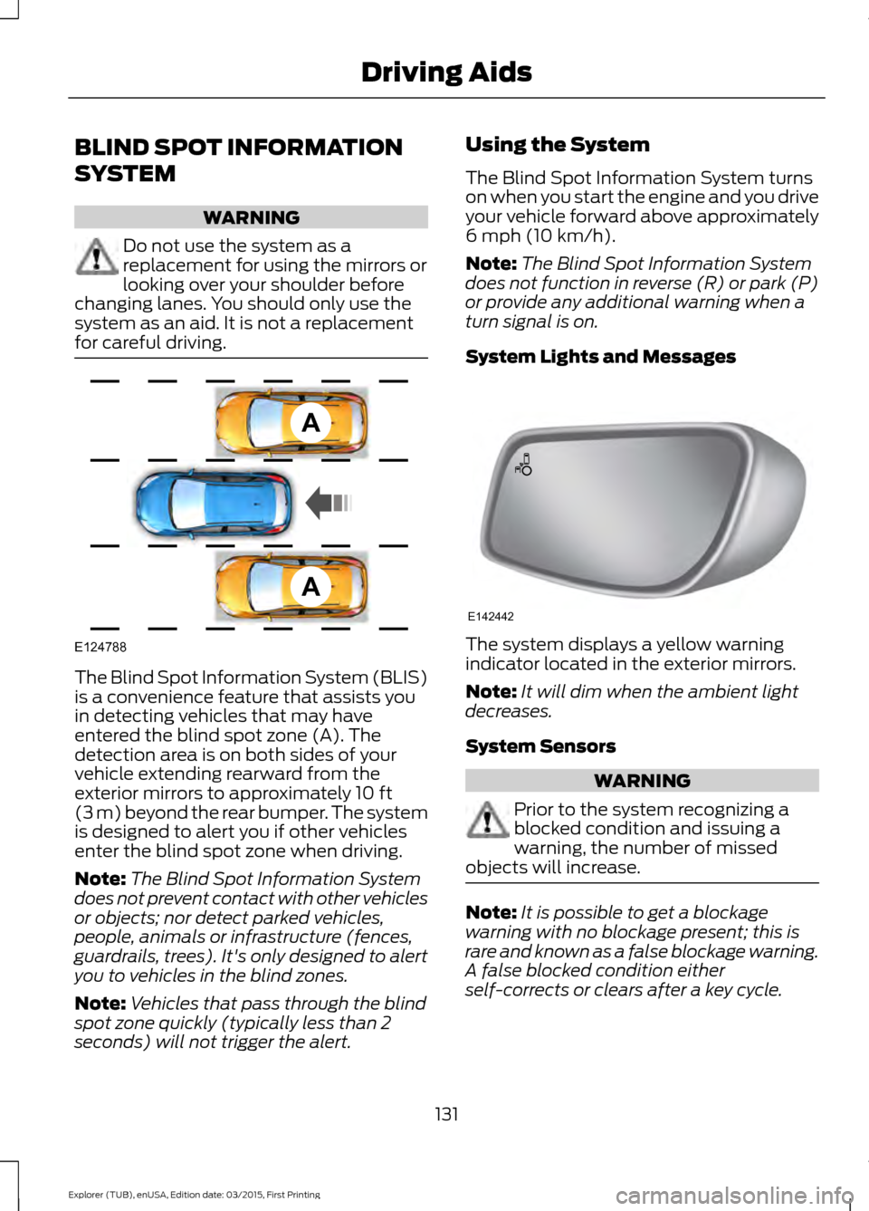
for careful driving. The Blind Spot Information System (BLIS)
is a convenience feature that assists you
in detecting vehicles that may have
entered the blind spot zone (A). The
detection area is on both sides of your
vehicle extending rearward from the
exterior mirrors to approximately 10 ft
(3 m) beyond the rear bumper. The system
is designed to alert you if other vehicles
enter the blind spot zone when driving.
Note: The Blind Spot Information System
does not prevent contact with other vehicles
or objects; nor detect parked vehicles,
people, animals or infrastructure (fences,
guardrails, trees). It's only designed to alert
you to vehicles in the blind zones.
Note: Vehicles that pass through the blind
spot zone quickly (typically less than 2
seconds) will not trigger the alert. Using the System
The Blind Spot Information System turns
on when you start the engine and you drive
your vehicle forward above approximately
6 mph (10 km/h)
.
Note: The Blind Spot Information System
does not function in reverse (R) or park (P)
or provide any additional warning when a
turn signal is on.
System Lights and Messages The system displays a yellow warning
indicator located in the exterior mirrors.
Note:
It will dim when the ambient light
decreases.
System Sensors WARNING
Prior to the system recognizing a
blocked condition and issuing a
warning, the number of missed
objects will increase. Note:
It is possible to get a blockage
warning with no blockage present; this is
rare and known as a false blockage warning.
A false blocked condition either
self-corrects or clears after a key cycle.
131
Explorer (TUB), enUSA, Edition date: 03/2015, First Printing Driving AidsA
A
E124788 E142442
Page 135 of 350
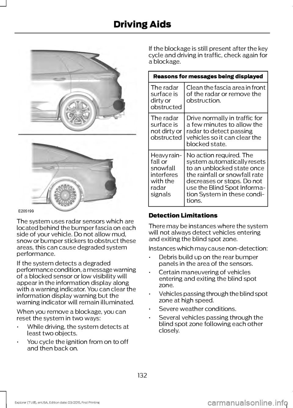
The system uses radar sensors which are
located behind the bumper fascia on each
side of your vehicle. Do not allow mud,
snow or bumper stickers to obstruct these
areas, this can cause degraded system
performance.
If the system detects a degraded
performance condition, a message warning
of a blocked sensor or low visibility will
appear in the information display along
with a warning indicator. You can clear the
information display warning but the
warning indicator will remain illuminated.
When you remove a blockage, you can
reset the system in two ways:
•
While driving, the system detects at
least two objects.
• You cycle the ignition from on to off
and then back on. If the blockage is still present after the key
cycle and driving in traffic, check again for
a blockage. Reasons for messages being displayed
Clean the fascia area in front
of the radar or remove the
obstruction.
The radar
surface is
dirty or
obstructed
Drive normally in traffic for
a few minutes to allow the
radar to detect passing
vehicles so it can clear the
blocked state.
The radar
surface is
not dirty or
obstructed
No action required. The
system automatically resets
to an unblocked state once
the rainfall or snowfall rate
decreases or stops. Do not
use the Blind Spot Informa-
tion System in these condi-
tions.
Heavy rain-
fall or
snowfall
interferes
with the
radar
signals
Detection Limitations
There may be instances where the system
will not always detect vehicles entering
and exiting the blind spot zone.
Instances which may cause non-detection:
• Debris build up on the rear bumper
panels in the area of the sensors.
• Certain maneuvering of vehicles
entering and exiting the blind spot
zone.
• Vehicles passing through the blind spot
zone at high speed.
• Severe weather conditions.
• Several vehicles passing through the
blind spot zone following each other
closely.
132
Explorer (TUB), enUSA, Edition date: 03/2015, First Printing Driving AidsE205199
Page 136 of 350
False Alerts
Note:
If your vehicle has a trailer tow
module approved by us, the system will
detect a connected trailer and turn off. For
non-factory equipped tow bars, you may
want to turn the Blind Spot Information
System off manually.
There may be certain instances when there
is a false alert by the system that
illuminates the alert indicator with no
vehicle in the coverage zone. Some
amount of false alerts are normal; they are
temporary and self-correct.
Detection Errors
If the system senses a problem with the
left or right sensor, the Blind Spot
Information System warning indicator will
illuminate and a message will appear in
the information display.
All other system faults will display only
with a message in the information display.
See Information Messages (page 76).
Switching the Systems Off and On
You can temporarily switch off the Blind
Spot Information System in the
information display. See
(page 73). When
you switch off the Blind Spot Information
System, you will not receive alerts and the
information display will display a system
off message.
Note: The Blind Spot Information System
will remember the last selected on or off
setting. The Blind Spot Information System cannot
be switched off when MyKey is used.
You can have the Blind Spot Information
System switched off permanently at an
authorized dealer. Once switched off, the
system can only be switched back on at
an authorized dealer.
CROSS TRAFFIC ALERT WARNING
To help avoid personal injury, NEVER
use the Cross Traffic Alert system as
a replacement for using the interior
and exterior mirrors and looking over your
shoulder before backing out of a parking
space. Cross Traffic Alert is not a
replacement for careful driving. Cross traffic alert is designed to warn you
of vehicles approaching from the sides
when the transmission is in reverse (R).
Using the System
Cross traffic alert turns on when you start
the engine and you shift into reverse (R).
Once shifted out of reverse (R), cross
traffic alert turns off.
Note:
Cross traffic alert is designed to
detect vehicles that approach with a speed
up to
37 mph (60 km/h). Coverage
decreases when the sensors are partially,
mostly or fully obstructed. Reversing slowly
helps increase the coverage area and
effectiveness.
133
Explorer (TUB), enUSA, Edition date: 03/2015, First Printing Driving Aids
Page 137 of 350
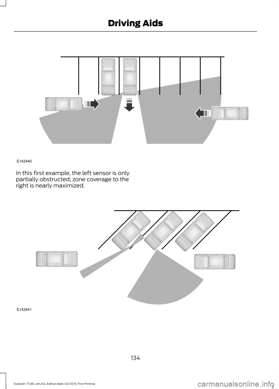
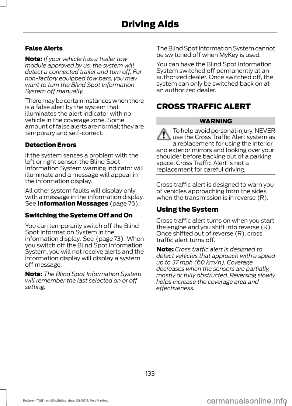
In this first example, the left sensor is only
partially obstructed; zone coverage to the
right is nearly maximized.
134
Explorer (TUB), enUSA, Edition date: 03/2015, First Printing Driving AidsE142440 E142441
Page 138 of 350
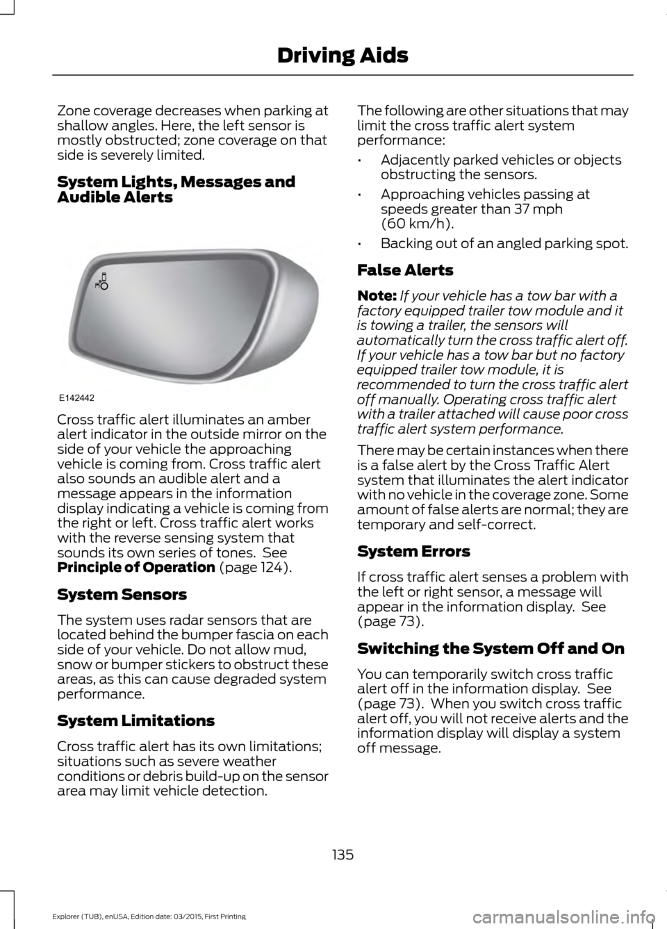
Zone coverage decreases when parking at
shallow angles. Here, the left sensor is
mostly obstructed; zone coverage on that
side is severely limited.
System Lights, Messages and
Audible Alerts
Cross traffic alert illuminates an amber
alert indicator in the outside mirror on the
side of your vehicle the approaching
vehicle is coming from. Cross traffic alert
also sounds an audible alert and a
message appears in the information
display indicating a vehicle is coming from
the right or left. Cross traffic alert works
with the reverse sensing system that
sounds its own series of tones. See
Principle of Operation (page 124).
System Sensors
The system uses radar sensors that are
located behind the bumper fascia on each
side of your vehicle. Do not allow mud,
snow or bumper stickers to obstruct these
areas, as this can cause degraded system
performance.
System Limitations
Cross traffic alert has its own limitations;
situations such as severe weather
conditions or debris build-up on the sensor
area may limit vehicle detection. The following are other situations that may
limit the cross traffic alert system
performance:
•
Adjacently parked vehicles or objects
obstructing the sensors.
• Approaching vehicles passing at
speeds greater than
37 mph
(60 km/h).
• Backing out of an angled parking spot.
False Alerts
Note: If your vehicle has a tow bar with a
factory equipped trailer tow module and it
is towing a trailer, the sensors will
automatically turn the cross traffic alert off.
If your vehicle has a tow bar but no factory
equipped trailer tow module, it is
recommended to turn the cross traffic alert
off manually. Operating cross traffic alert
with a trailer attached will cause poor cross
traffic alert system performance.
There may be certain instances when there
is a false alert by the Cross Traffic Alert
system that illuminates the alert indicator
with no vehicle in the coverage zone. Some
amount of false alerts are normal; they are
temporary and self-correct.
System Errors
If cross traffic alert senses a problem with
the left or right sensor, a message will
appear in the information display. See
(page
73).
Switching the System Off and On
You can temporarily switch cross traffic
alert off in the information display. See
(page
73). When you switch cross traffic
alert off, you will not receive alerts and the
information display will display a system
off message.
135
Explorer (TUB), enUSA, Edition date: 03/2015, First Printing Driving AidsE142442
Page 176 of 350
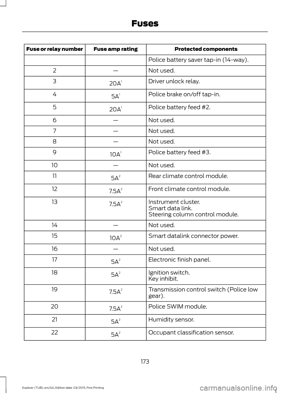
Protected components
Fuse amp rating
Fuse or relay number
Police battery saver tap-in (14-way).
Not used.
—
2
Driver unlock relay.
20A 1
3
Police brake on/off tap-in.
5A 1
4
Police battery feed #2.
20A 1
5
Not used.
—
6
Not used.
—
7
Not used.
—
8
Police battery feed #3.
10A 1
9
Not used.
—
10
Rear climate control module.
5A 2
11
Front climate control module.
7.5A 2
12
Instrument cluster.
7.5A 2
13
Smart data link.
Steering column control module.
Not used.
—
14
Smart datalink connector power.
10A 2
15
Not used.
—
16
Electronic finish panel.
5A 2
17
Ignition switch.
5A 2
18
Key inhibit.
Transmission control switch (Police low
gear).
7.5A
2
19
Police SWIM module.
7.5A 2
20
Humidity sensor.
5A 2
21
Occupant classification sensor.
5A 2
22
173
Explorer (TUB), enUSA, Edition date: 03/2015, First Printing Fuses
Page 221 of 350
WARNINGS
is located on the B-Pillar or edge
of the driver ’s door. If this
information is not found on these
labels then you should contact
your authorized dealer as soon as
possible. Use of any tire or wheel
not recommended by Ford can
affect the safety and performance
of your vehicle, which could result
in an increased risk of loss of
vehicle control, vehicle rollover,
personal injury and death.
Additionally the use of
non-recommended tires and
wheels could cause steering,
suspension, axle, transfer case or
power transfer unit failure. If you
have questions regarding tire
replacement, contact your
authorized dealer as soon as
possible. To reduce the risk of serious
injury, when mounting
replacement tires and wheels, you
should not exceed the maximum
pressure indicated on the sidewall
of the tire to set the beads without
additional precautions listed
below. If the beads do not seat at
the maximum pressure indicated,
re-lubricate and try again.
When inflating the tire for
mounting pressures up to 20 psi
(1.38 bar) greater than the
maximum pressure on the tire
sidewall, the following
precautions must be taken to
protect the person mounting the
tire: WARNINGS
1. Make sure that you have the
correct tire and wheel size.
2. Lubricate the tire bead and
wheel bead seat area again.
3. Stand at a minimum of
12 ft
(3.66 m) away from the wheel
and tire assembly.
4. Use both eye and ear
protection.
For a mounting pressure more
than 20 psi (1.38 bar) greater than
the maximum pressure, a Ford
dealer or other tire service
professional should do the
mounting.
Always inflate steel carcass tires
with a remote air fill with the
person inflating standing at a
minimum of 12 feet (3.66 meters)
away from the wheel and tire
assembly. Important: Remember to replace
the wheel valve stems when the
road tires are replaced on your
vehicle.
It is recommended that the two
front tires or two rear tires
generally be replaced as a pair.
The tire pressure sensors mounted
in the wheels (originally installed
on your vehicle) are not designed
to be used in aftermarket wheels.
218
Explorer (TUB), enUSA, Edition date: 03/2015, First Printing Wheels and Tires
Page 227 of 350
Please note that the TPMS is not a
substitute for proper tire maintenance, and
it is the driver
’s responsibility to maintain
correct tire pressure, even if under-inflation
has not reached the level to trigger
illumination of the TPMS low tire pressure
telltale.
Your vehicle has also been equipped with
a TPMS malfunction indicator to indicate
when the system is not operating properly.
The TPMS malfunction indicator is
combined with the low tire pressure
telltale. When the system detects a
malfunction, the telltale will flash for
approximately one minute and then remain
continuously illuminated. This sequence
will continue upon subsequent vehicle
start-ups as long as the malfunction exists.
When the malfunction indicator is
illuminated, the system may not be able
to detect or signal low tire pressure as
intended. TPMS malfunctions may occur
for a variety of reasons, including the
installation of replacement or alternate
tires or wheels on the vehicle that prevent
the TPMS from functioning properly.
Always check the TPMS malfunction
telltale after replacing one or more tires or
wheels on your vehicle to ensure that the
replacement or alternate tires and wheels
allow the TPMS to continue to function
properly.
The tire pressure monitoring system
complies with part 15 of the FCC rules and
with RSS-210 of Industry Canada.
Operation is subject to the following two
conditions: (1) This device may not cause
harmful interference, and (2) This device
must accept any interference received,
including interference that may cause
undesired operation. Changing Tires With a Tire
Pressure Monitoring System
Note:
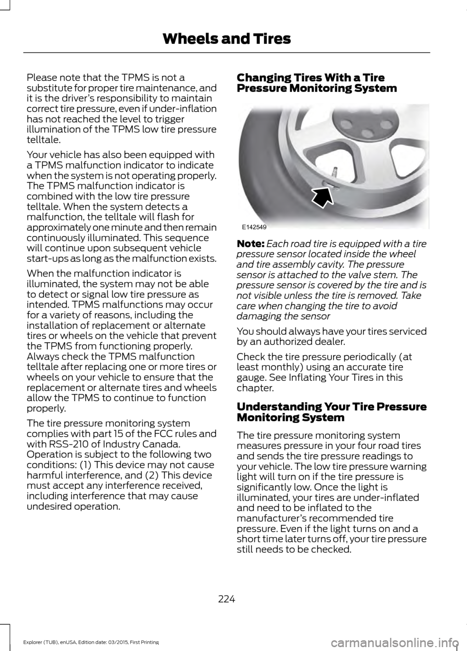
Each road tire is equipped with a tire
pressure sensor located inside the wheel
and tire assembly cavity. The pressure
sensor is attached to the valve stem. The
pressure sensor is covered by the tire and is
not visible unless the tire is removed. Take
care when changing the tire to avoid
damaging the sensor
You should always have your tires serviced
by an authorized dealer.
Check the tire pressure periodically (at
least monthly) using an accurate tire
gauge. See Inflating Your Tires in this
chapter.
Understanding Your Tire Pressure
Monitoring System
The tire pressure monitoring system
measures pressure in your four road tires
and sends the tire pressure readings to
your vehicle. The low tire pressure warning
light will turn on if the tire pressure is
significantly low. Once the light is
illuminated, your tires are under-inflated
and need to be inflated to the
manufacturer ’s recommended tire
pressure. Even if the light turns on and a
short time later turns off, your tire pressure
still needs to be checked.
224
Explorer (TUB), enUSA, Edition date: 03/2015, First Printing Wheels and TiresE142549
Page 230 of 350
How Temperature Affects Your Tire
Pressure
The tire pressure monitoring system
monitors tire pressure in each pneumatic
tire. While driving in a normal manner, a
typical passenger tire inflation pressure
may increase about 2 to 4 psi (14 to 28
kPa) from a cold start situation. If the
vehicle is stationary overnight with the
outside temperature significantly lower
than the daytime temperature, the tire
pressure may decrease about 3 psi (21
kPa) for a drop of 30°F (17°C) in ambient
temperature. This lower pressure value
may be detected by the tire pressure
monitoring system as being significantly
lower than the recommended inflation
pressure and activate the system warning
light for low tire pressure. If the low tire
pressure warning light is on, visually check
each tire to verify that no tire is flat. If one
or more tires are flat, repair as necessary.
Check the air pressure in the road tires. If
any tire is under-inflated, carefully drive
the vehicle to the nearest location where
air can be added to the tires. Inflate all the
tires to the recommended inflation
pressure.
CHANGING A ROAD WHEEL
WARNINGS
The use of tire sealant may damage
your tire pressure monitoring system
and should only be used in roadside
emergencies. If you must use a sealant, the
Ford Tire Mobility Kit sealant should be
used. The tire pressure monitoring system
sensor and valve stem on the wheel must
be replaced by an authorized dealer after
use of the sealant. See Tire Pressure Monitoring
System (page 223). If the tire
pressure monitor sensor becomes
damaged, it will no longer function. Note:
The tire pressure monitoring system
indicator light will illuminate when the spare
tire is in use. To restore the full function of
the monitoring system, all road wheels
equipped with tire pressure monitoring
sensors must be mounted on the vehicle.
If you get a flat tire while driving, do not
apply the brake heavily. Instead, gradually
decrease your speed. Hold the steering
wheel firmly and slowly move to a safe
place on the side of the road.
Have a flat serviced by an authorized
dealer in order to prevent damage to the
tire pressure monitoring system sensors.
See
Tire Pressure Monitoring System
(page 223). Replace the spare tire with a
road tire as soon as possible. During
repairing or replacing of the flat tire, have
the authorized dealer inspect the tire
pressure monitoring system sensor for
damage.
Dissimilar Spare Wheel and Tire
Assembly Information WARNING
Failure to follow these guidelines
could result in an increased risk of
loss of vehicle control, injury or death.
If you have a dissimilar spare wheel and
tire, then it is intended for temporary use
only. This means that if you need to use it,
you should replace it as soon as possible
with a road wheel and tire assembly that
is the same size and type as the road tires
and wheels that were originally provided
by Ford. If the dissimilar spare tire or wheel
is damaged, it should be replaced rather
than repaired.
A dissimilar spare wheel and tire assembly
is defined as a spare wheel and tire
assembly that is different in brand, size or
appearance from the road tires and wheels
and can be one of three types:
227
Explorer (TUB), enUSA, Edition date: 03/2015, First Printing Wheels and Tires