engine FORD RANGER 2002 2.G Service Manual
[x] Cancel search | Manufacturer: FORD, Model Year: 2002, Model line: RANGER, Model: FORD RANGER 2002 2.GPages: 288, PDF Size: 3.03 MB
Page 194 of 288
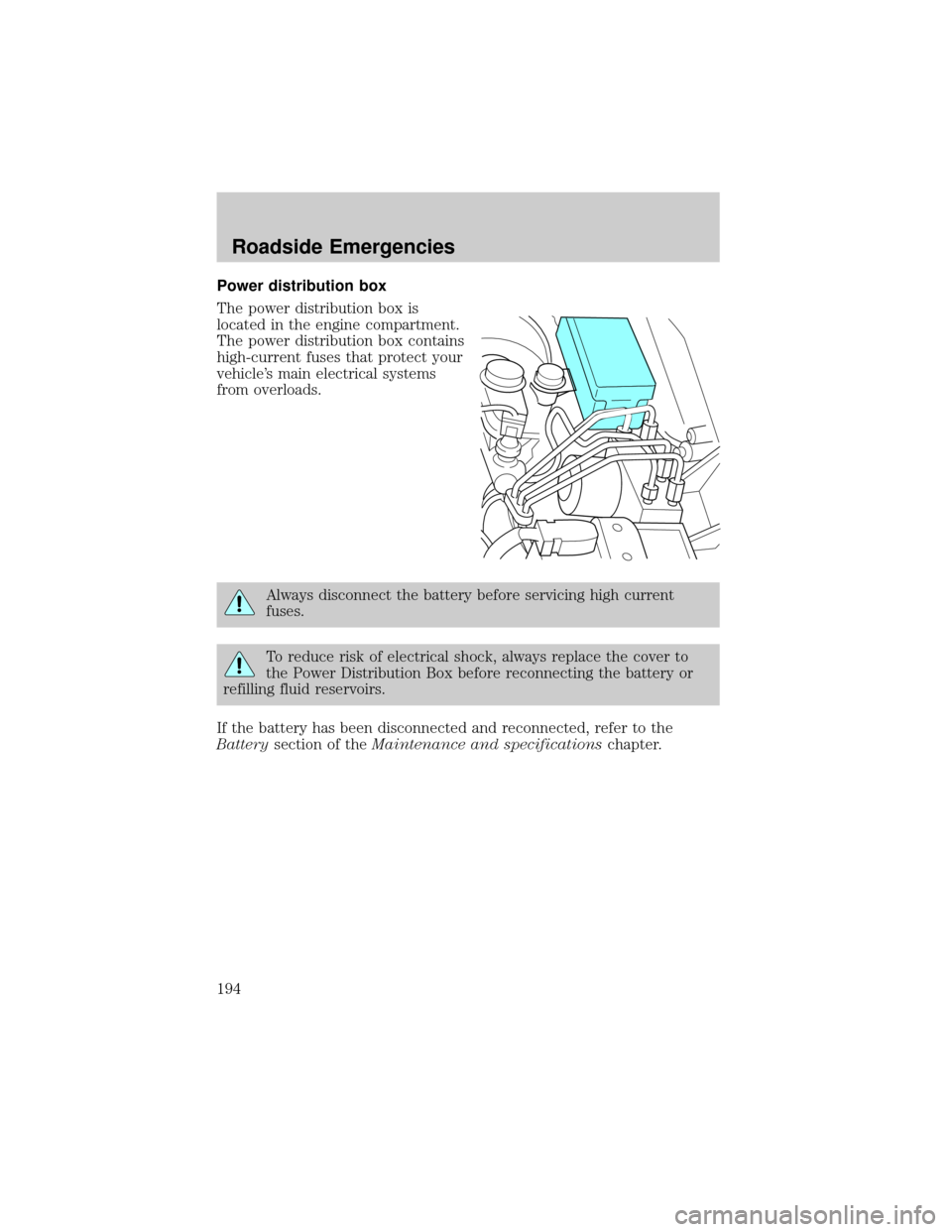
Power distribution box
The power distribution box is
located in the engine compartment.
The power distribution box contains
high-current fuses that protect your
vehicle's main electrical systems
from overloads.
Always disconnect the battery before servicing high current
fuses.
To reduce risk of electrical shock, always replace the cover to
the Power Distribution Box before reconnecting the battery or
refilling fluid reservoirs.
If the battery has been disconnected and reconnected, refer to the
Batterysection of theMaintenance and specificationschapter.
Roadside Emergencies
194
Page 195 of 288
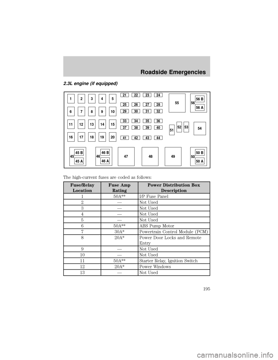
2.3L engine (if equipped)
The high-current fuses are coded as follows:
Fuse/Relay
LocationFuse Amp
RatingPower Distribution Box
Description
1 50A** I/P Fuse Panel
2 Ð Not Used
3 Ð Not Used
4 Ð Not Used
5 Ð Not Used
6 50A** ABS Pump Motor
7 30A* Powertrain Control Module (PCM)
8 20A* Power Door Locks and Remote
Entry
9 Ð Not Used
10 Ð Not Used
11 50A** Starter Relay, Ignition Switch
12 20A* Power Windows
13 Ð Not Used
1234521 22 23 24
25 26 27 28
29 30 31 32
33 34 35 36
37 38 39 40
41 42 43 44
67891055
49 4854 53 52
515656 B
56 A
5050 B
50 A 47 4545 B
45 A
4646 B
46 A 11 12 13 14 15
16 17 18 19 20
Roadside Emergencies
195
Page 198 of 288
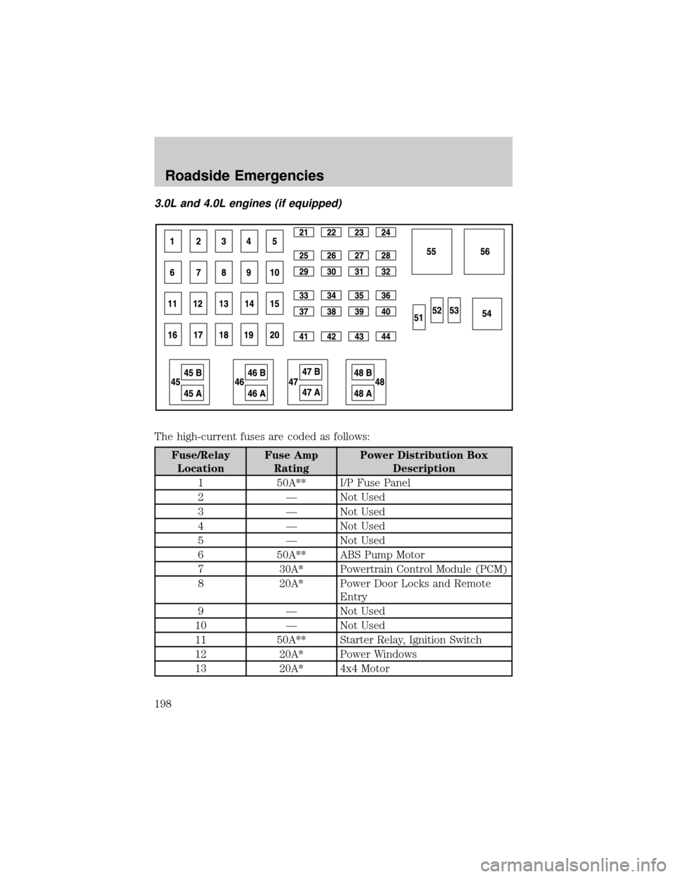
3.0L and 4.0L engines (if equipped)
The high-current fuses are coded as follows:
Fuse/Relay
LocationFuse Amp
RatingPower Distribution Box
Description
1 50A** I/P Fuse Panel
2 Ð Not Used
3 Ð Not Used
4 Ð Not Used
5 Ð Not Used
6 50A** ABS Pump Motor
7 30A* Powertrain Control Module (PCM)
8 20A* Power Door Locks and Remote
Entry
9 Ð Not Used
10 Ð Not Used
11 50A** Starter Relay, Ignition Switch
12 20A* Power Windows
13 20A* 4x4 Motor
Roadside Emergencies
198
Page 204 of 288
Tire change procedure
To prevent the vehicle from moving when you change a tire, be
sure the parking brake is set, then block (in both directions) the
wheel that is diagonally opposite (other side and end of the vehicle) to
the tire being changed.
If the vehicle slips off the jack, you or someone else could be
seriously injured.
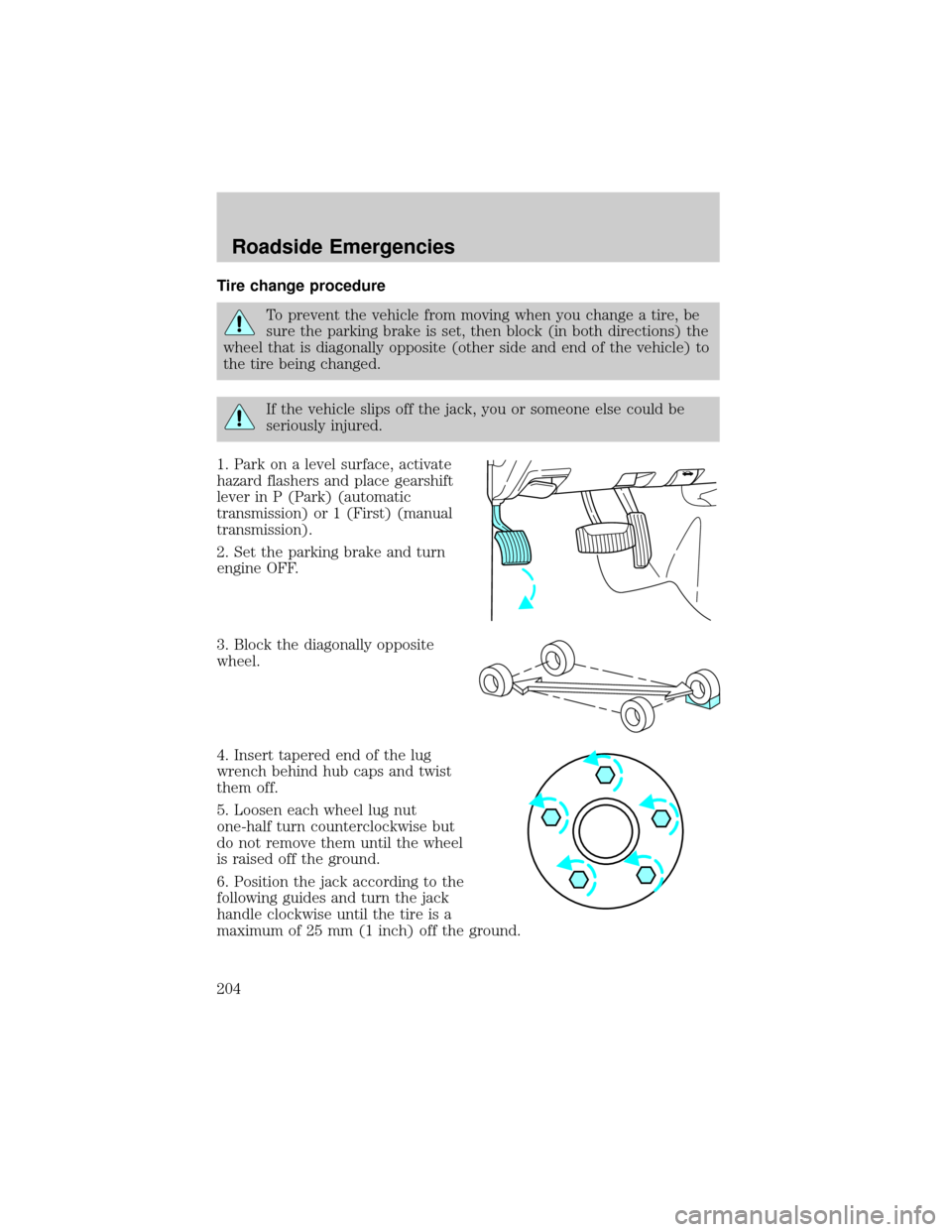
1. Park on a level surface, activate
hazard flashers and place gearshift
lever in P (Park) (automatic
transmission) or 1 (First) (manual
transmission).
2. Set the parking brake and turn
engine OFF.
3. Block the diagonally opposite
wheel.
4. Insert tapered end of the lug
wrench behind hub caps and twist
them off.
5. Loosen each wheel lug nut
one-half turn counterclockwise but
do not remove them until the wheel
is raised off the ground.
6. Position the jack according to the
following guides and turn the jack
handle clockwise until the tire is a
maximum of 25 mm (1 inch) off the ground.
Roadside Emergencies
204
Page 205 of 288
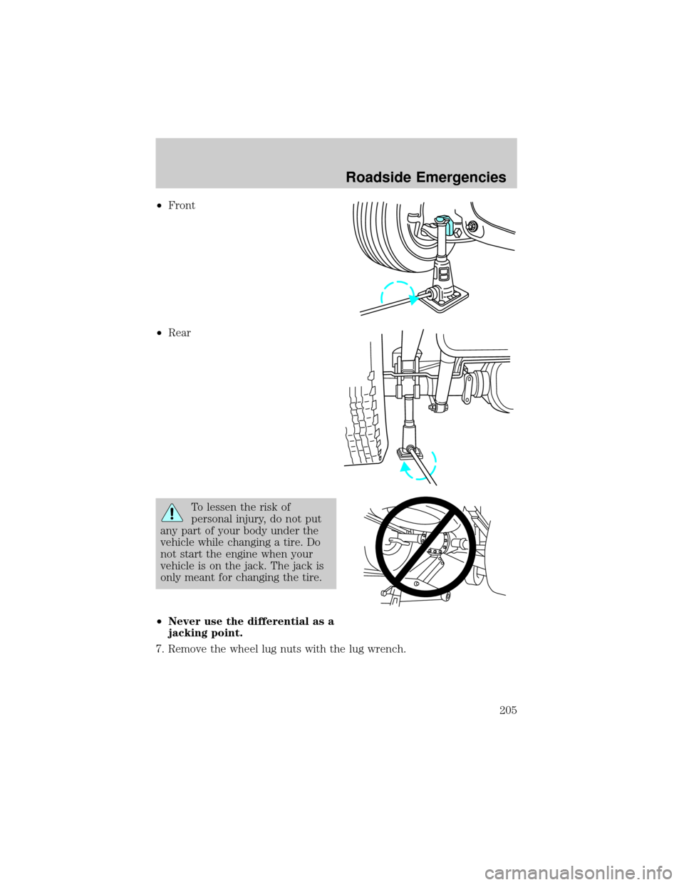
²Front
²Rear
To lessen the risk of
personal injury, do not put
any part of your body under the
vehicle while changing a tire. Do
not start the engine when your
vehicle is on the jack. The jack is
only meant for changing the tire.
²Never use the differential as a
jacking point.
7. Remove the wheel lug nuts with the lug wrench.
Roadside Emergencies
205
Page 207 of 288
3. Park the booster vehicle close to the hood of the disabled vehicle
making sure the two vehiclesdo nottouch. Set the parking brake on
both vehicles and stay clear of the engine cooling fan and other moving
parts.
4. Check all battery terminals and remove any excessive corrosion before
you attach the battery cables. Ensure that vent caps are tight and level.
5. Turn the heater fan on in both vehicles to protect any electrical
surges. Turn all other accessories off.
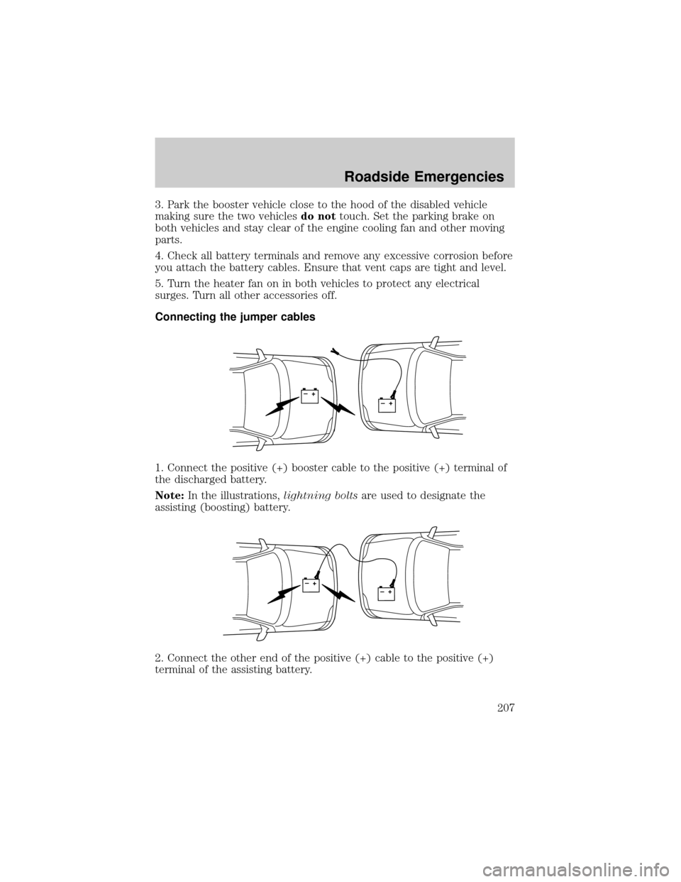
Connecting the jumper cables
1. Connect the positive (+) booster cable to the positive (+) terminal of
the discharged battery.
Note:In the illustrations,lightning boltsare used to designate the
assisting (boosting) battery.
2. Connect the other end of the positive (+) cable to the positive (+)
terminal of the assisting battery.
+–+–
+–+–
Roadside Emergencies
207
Page 208 of 288
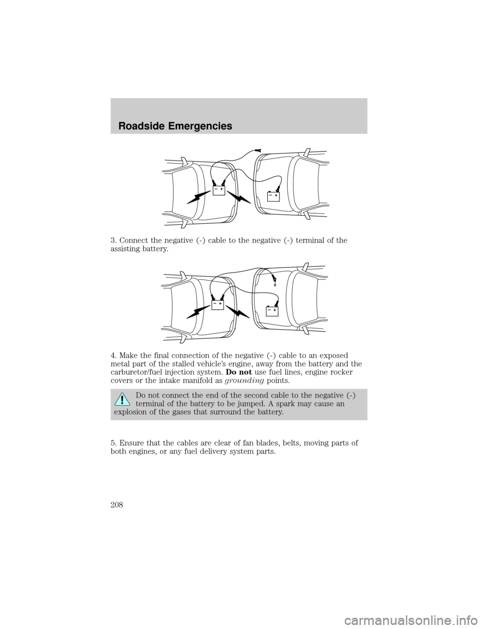
3. Connect the negative (-) cable to the negative (-) terminal of the
assisting battery.
4. Make the final connection of the negative (-) cable to an exposed
metal part of the stalled vehicle's engine, away from the battery and the
carburetor/fuel injection system.Do notuse fuel lines, engine rocker
covers or the intake manifold asgroundingpoints.
Do not connect the end of the second cable to the negative (-)
terminal of the battery to be jumped. A spark may cause an
explosion of the gases that surround the battery.
5. Ensure that the cables are clear of fan blades, belts, moving parts of
both engines, or any fuel delivery system parts.
+–+–
+–+–
Roadside Emergencies
208
Page 209 of 288
Jump starting
1. Start the engine of the booster vehicle and run the engine at
moderately increased speed.
2. Start the engine of the disabled vehicle.
3. Once the disabled vehicle has been started, run both engines for an
additional three minutes before disconnecting the jumper cables.
Removing the jumper cables
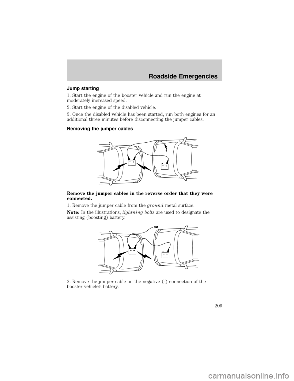
Remove the jumper cables in the reverse order that they were
connected.
1. Remove the jumper cable from thegroundmetal surface.
Note:In the illustrations,lightning boltsare used to designate the
assisting (boosting) battery.
2. Remove the jumper cable on the negative (-) connection of the
booster vehicle's battery.
+–+–
+–+–
Roadside Emergencies
209
Page 210 of 288
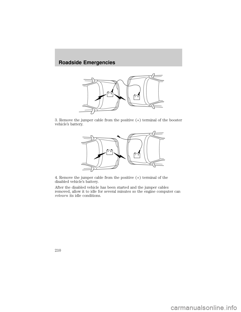
3. Remove the jumper cable from the positive (+) terminal of the booster
vehicle's battery.
4. Remove the jumper cable from the positive (+) terminal of the
disabled vehicle's battery.
After the disabled vehicle has been started and the jumper cables
removed, allow it to idle for several minutes so the engine computer can
relearnits idle conditions.
+–+–
+–+–
Roadside Emergencies
210
Page 218 of 288

UTILIZING THE MEDIATION/ARBITRATION PROGRAM
(CANADA ONLY)
In those cases where you continue to feel that the efforts by Ford and
the dealer to resolve a factory-related vehicle service concern have been
unsatisfactory, Ford of Canada participates in an impartial third party
mediation/arbitration program administered by the Canadian Motor
Vehicle Arbitration Plan (CAMVAP).
The CAMVAP program is a straight-forward and relatively speedy
alternative to resolve a disagreement when all other efforts to produce a
settlement have failed. This procedure is without cost to you and is
designed to eliminate the need for lengthy and expensive legal
proceedings.
In the CAMVAP program, impartial third-party arbitrators conduct
hearings at mutually convenient times and places in an informal
environment. These impartial arbitrators review the positions of the
parties, make decisions and, when appropriate, render awards to resolve
disputes. CAMVAP decisions are fast, fair, and final; the arbitrator's
award is binding both to you and Ford of Canada.
CAMVAP services are available in all territories and provinces. For more
information, without charge or obligation, call your CAMVAP Provincial
Administrator directly at 1-800-207-0685.
GETTING ASSISTANCE OUTSIDE THE U.S. AND CANADA
Before exporting your vehicle to a foreign country, contact the
appropriate foreign embassy or consulate. These officials can inform you
of local vehicle registration regulations and where to find unleaded fuel.
If you cannot find unleaded fuel or can only get fuel with an anti-knock
index lower than is recommended for your vehicle, contact a district or
owner relations/customer relationship office.
The use of leaded fuel in your vehicle without proper conversion may
damage the effectiveness of your emission control system and may cause
engine knocking or serious engine damage. Ford Motor Company/Ford of
Canada is not responsible for any damage caused by use of improper
fuel.
In the United States, using leaded fuel may also result in difficulty
importing your vehicle back into the U.S.
Customer Assistance
218