ABS FORD RANGER 2002 2.G Owners Manual
[x] Cancel search | Manufacturer: FORD, Model Year: 2002, Model line: RANGER, Model: FORD RANGER 2002 2.GPages: 288, PDF Size: 3.03 MB
Page 12 of 288
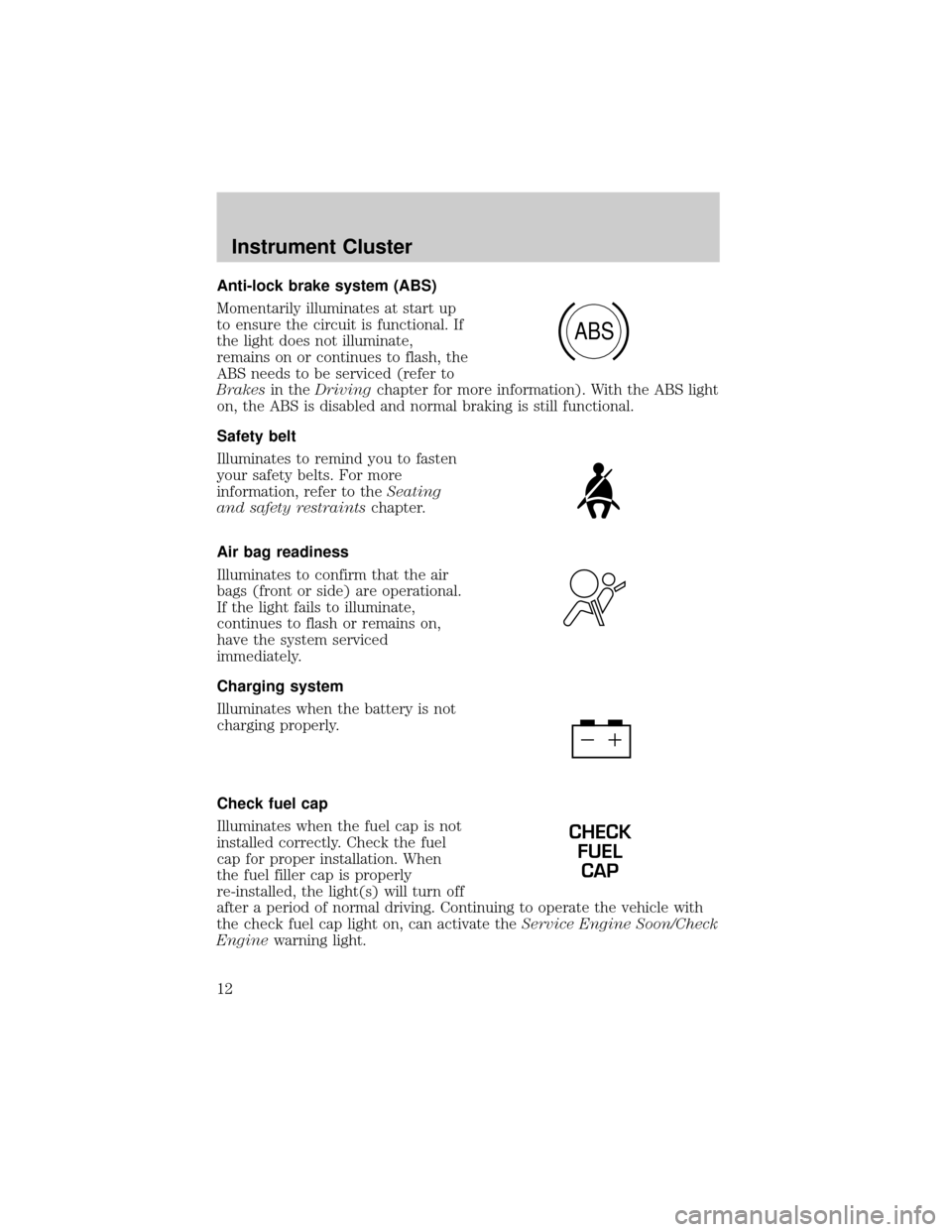
Anti-lock brake system (ABS)
Momentarily illuminates at start up
to ensure the circuit is functional. If
the light does not illuminate,
remains on or continues to flash, the
ABS needs to be serviced (refer to
Brakesin theDrivingchapter for more information). With the ABS light
on, the ABS is disabled and normal braking is still functional.
Safety belt
Illuminates to remind you to fasten
your safety belts. For more
information, refer to theSeating
and safety restraintschapter.
Air bag readiness
Illuminates to confirm that the air
bags (front or side) are operational.
If the light fails to illuminate,
continues to flash or remains on,
have the system serviced
immediately.
Charging system
Illuminates when the battery is not
charging properly.
Check fuel cap
Illuminates when the fuel cap is not
installed correctly. Check the fuel
cap for proper installation. When
the fuel filler cap is properly
re-installed, the light(s) will turn off
after a period of normal driving. Continuing to operate the vehicle with
the check fuel cap light on, can activate theService Engine Soon/Check
Enginewarning light.
ABS
CHECK
FUEL
CAP
Instrument Cluster
12
Page 78 of 288
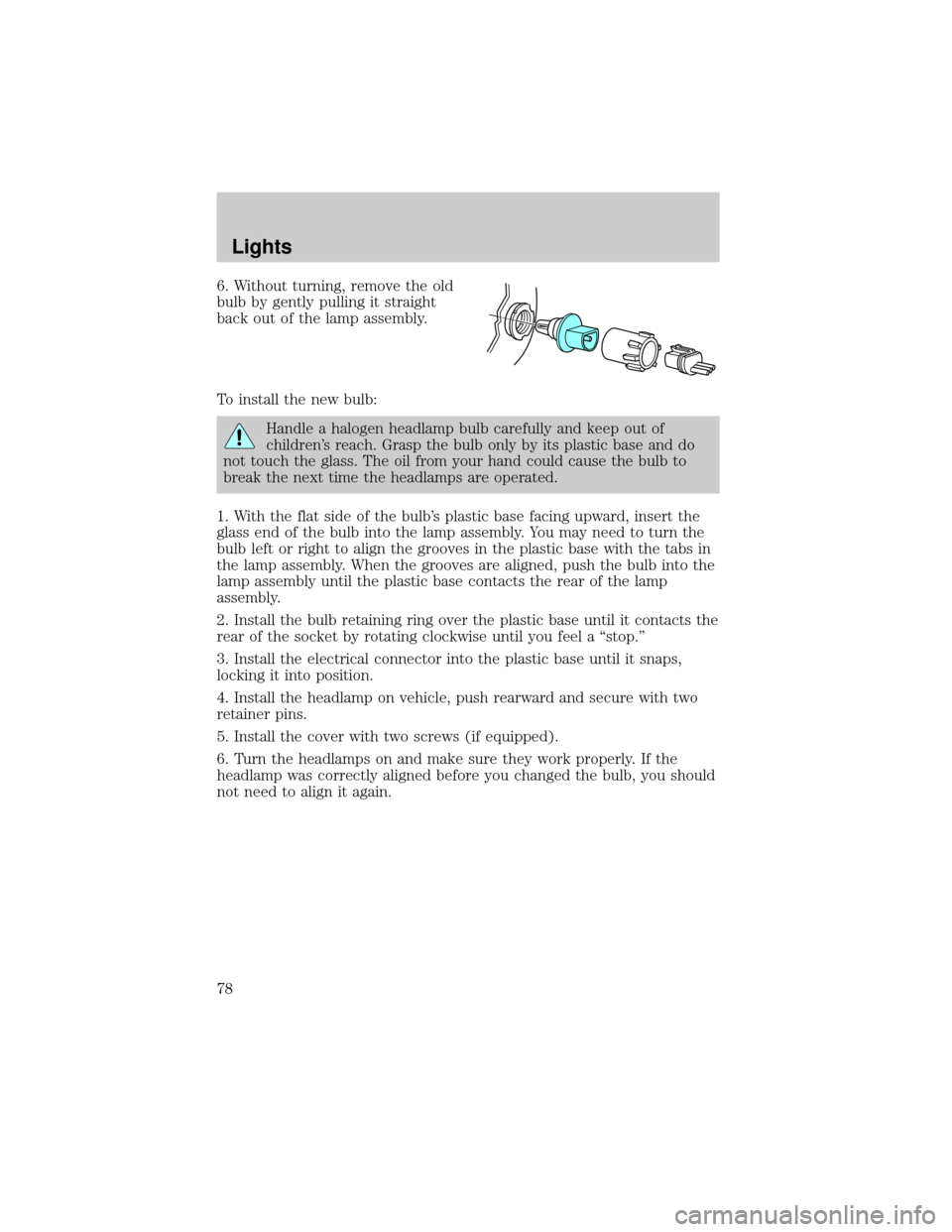
6. Without turning, remove the old
bulb by gently pulling it straight
back out of the lamp assembly.
To install the new bulb:
Handle a halogen headlamp bulb carefully and keep out of
children's reach. Grasp the bulb only by its plastic base and do
not touch the glass. The oil from your hand could cause the bulb to
break the next time the headlamps are operated.
1. With the flat side of the bulb's plastic base facing upward, insert the
glass end of the bulb into the lamp assembly. You may need to turn the
bulb left or right to align the grooves in the plastic base with the tabs in
the lamp assembly. When the grooves are aligned, push the bulb into the
lamp assembly until the plastic base contacts the rear of the lamp
assembly.
2. Install the bulb retaining ring over the plastic base until it contacts the
rear of the socket by rotating clockwise until you feel a ªstop.º
3. Install the electrical connector into the plastic base until it snaps,
locking it into position.
4. Install the headlamp on vehicle, push rearward and secure with two
retainer pins.
5. Install the cover with two screws (if equipped).
6. Turn the headlamps on and make sure they work properly. If the
headlamp was correctly aligned before you changed the bulb, you should
not need to align it again.
Lights
78
Page 123 of 288
there are no nicks, tears or cuts. Replace if necessary. All safety belt
assemblies, including retractors, buckles, front seat belt buckle
assemblies, buckle support assemblies (slide bar-if equipped), shoulder
belt height adjusters (if equipped), shoulder belt guide on seatback (if
equipped), child safety seat tether bracket assemblies (if equipped),
LATCH child seat tether anchors and lower anchors (if equipped), and
attaching hardware, should be inspected after a collision. Ford Motor
Company recommends that all safety belt assemblies used in vehicles
involved in a collision be replaced. However, if the collision was minor
and a qualified technician finds that the belts do not show damage and
continue to operate properly, they do not need to be replaced. Safety
belt assemblies not in use during a collision should also be inspected and
replaced if either damage or improper operation is noted.
Failure to inspect and if necessary replace the safety belt
assembly under the above conditions could result in severe
personal injuries in the event of a collision.
Refer toCleaning and maintaining the safety beltsin theCleaning
chapter.
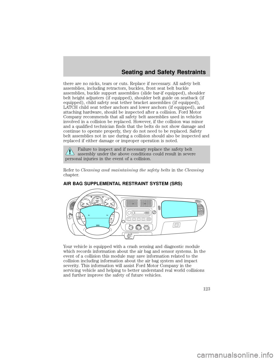
AIR BAG SUPPLEMENTAL RESTRAINT SYSTEM (SRS)
Your vehicle is equipped with a crash sensing and diagnostic module
which records information about the air bag and sensor systems. In the
event of a collision this module may save information related to the
collision including information about the air bag system and impact
severity. This information will assist Ford Motor Company in the
servicing vehicle and helping to better understand real world collisions
and further improve the safety of future vehicles.
OFFRSM
SET
ACC
COAST OFF ON
SRS
ABS
CHECK
ENGINEFH
H
H
!
PBRAKEELSPEED
CONTO/D
OFFPRND21LL10MPH 205060
70
304080
90
km/h
0 0 010 100
1
20
10 0 0 0 0 0406080100
120
140
160
180
20
O
FFA/CM
AX
A/C
TUNESEEK
12
34AM-FM
ON
OFF
OFF
PASSENGER AIRBAG
Seating and Safety Restraints
123
Page 149 of 288
aggravated by environmental conditions such as cold, heat, moisture,
road dust, salt or mud. If a ªmetal-to-metal,º ªcontinuous grindingº or
ªcontinuous squealº sound is present while braking, the brake linings
may be worn-out and should be inspected by a qualified service
technician.
Four-wheel anti-lock brake system (ABS)
This vehicle is equipped with an anti-lock braking system (ABS). A noise
from the hydraulic pump motor and pulsation in the pedal may be
observed during ABS braking events. Pedal pulsation coupled with noise
while braking under panic conditions or on loose gravel, bumps, wet or
snowy roads is normal and indicates proper functioning of the vehicle's
anti-lock brake system. If the vehicle has continuous vibration or shudder
in the steering wheel while braking, the vehicle should be inspected by a
qualified service technician.
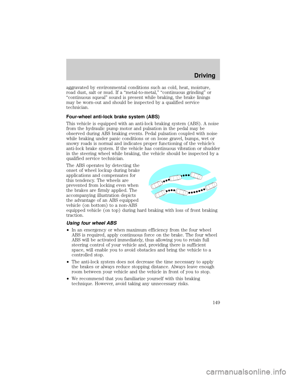
The ABS operates by detecting the
onset of wheel lockup during brake
applications and compensates for
this tendency. The wheels are
prevented from locking even when
the brakes are firmly applied. The
accompanying illustration depicts
the advantage of an ABS equipped
vehicle (on bottom) to a non-ABS
equipped vehicle (on top) during hard braking with loss of front braking
traction.
Using four wheel ABS
²In an emergency or when maximum efficiency from the four wheel
ABS is required, apply continuous force on the brake. The four wheel
ABS will be activated immediately, thus allowing you to retain full
steering control of your vehicle and, providing there is sufficient
space, will enable you to avoid obstacles and bring the vehicle to a
controlled stop.
²The anti-lock system does not decrease the time necessary to apply
the brakes or always reduce stopping distance. Always leave enough
room between your vehicle and the vehicle in front of you to stop.
²We recommend that you familiarize yourself with this braking
technique. However, avoid taking any unnecessary risks.
Driving
149
Page 150 of 288
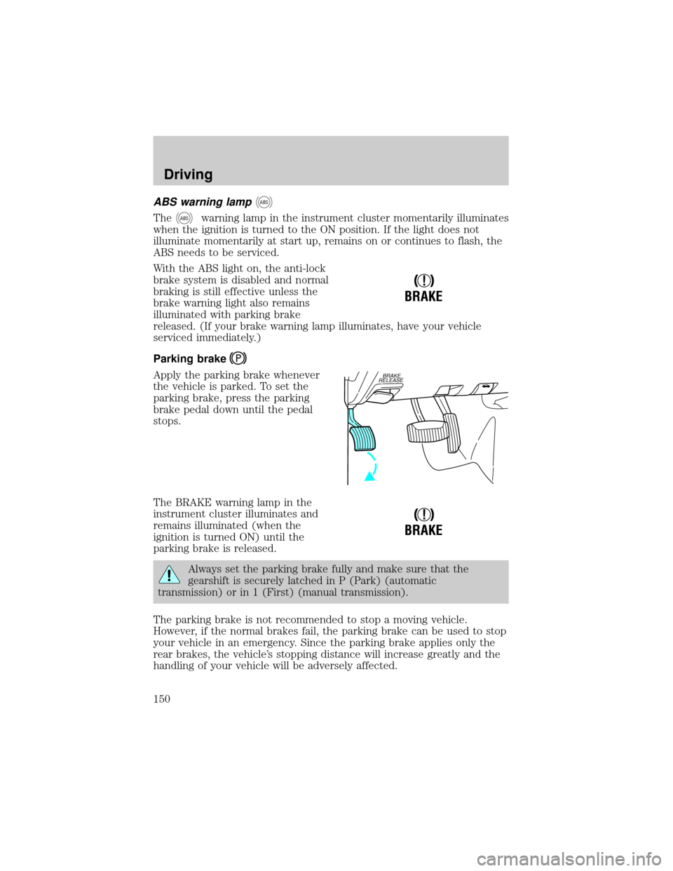
ABS warning lampABS
TheABSwarning lamp in the instrument cluster momentarily illuminates
when the ignition is turned to the ON position. If the light does not
illuminate momentarily at start up, remains on or continues to flash, the
ABS needs to be serviced.
With the ABS light on, the anti-lock
brake system is disabled and normal
braking is still effective unless the
brake warning light also remains
illuminated with parking brake
released. (If your brake warning lamp illuminates, have your vehicle
serviced immediately.)
Parking brake
Apply the parking brake whenever
the vehicle is parked. To set the
parking brake, press the parking
brake pedal down until the pedal
stops.
The BRAKE warning lamp in the
instrument cluster illuminates and
remains illuminated (when the
ignition is turned ON) until the
parking brake is released.
Always set the parking brake fully and make sure that the
gearshift is securely latched in P (Park) (automatic
transmission) or in 1 (First) (manual transmission).
The parking brake is not recommended to stop a moving vehicle.
However, if the normal brakes fail, the parking brake can be used to stop
your vehicle in an emergency. Since the parking brake applies only the
rear brakes, the vehicle's stopping distance will increase greatly and the
handling of your vehicle will be adversely affected.
!
BRAKE
BRAKE
RELEASE
!
BRAKE
Driving
150
Page 170 of 288
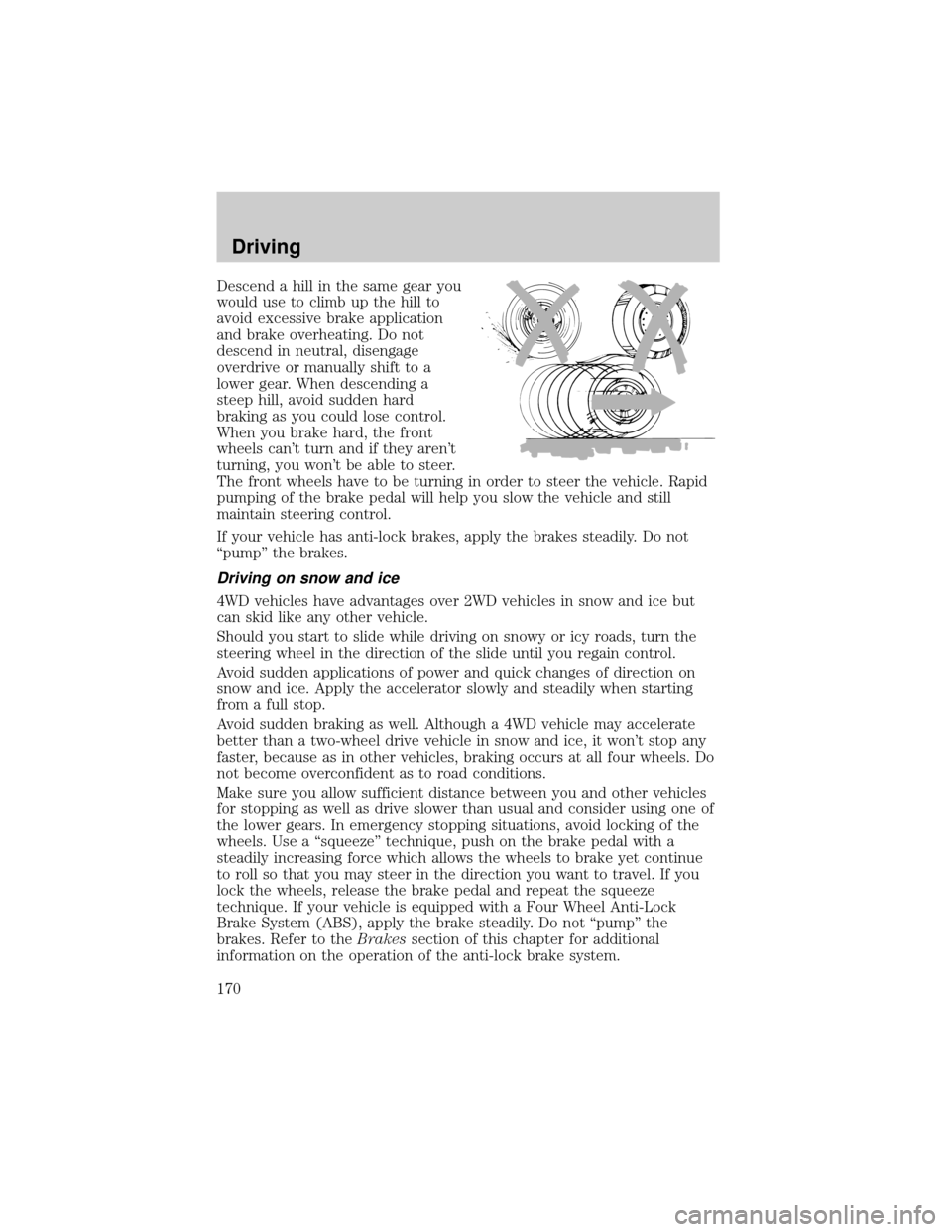
Descend a hill in the same gear you
would use to climb up the hill to
avoid excessive brake application
and brake overheating. Do not
descend in neutral, disengage
overdrive or manually shift to a
lower gear. When descending a
steep hill, avoid sudden hard
braking as you could lose control.
When you brake hard, the front
wheels can't turn and if they aren't
turning, you won't be able to steer.
The front wheels have to be turning in order to steer the vehicle. Rapid
pumping of the brake pedal will help you slow the vehicle and still
maintain steering control.
If your vehicle has anti-lock brakes, apply the brakes steadily. Do not
ªpumpº the brakes.
Driving on snow and ice
4WD vehicles have advantages over 2WD vehicles in snow and ice but
can skid like any other vehicle.
Should you start to slide while driving on snowy or icy roads, turn the
steering wheel in the direction of the slide until you regain control.
Avoid sudden applications of power and quick changes of direction on
snow and ice. Apply the accelerator slowly and steadily when starting
from a full stop.
Avoid sudden braking as well. Although a 4WD vehicle may accelerate
better than a two-wheel drive vehicle in snow and ice, it won't stop any
faster, because as in other vehicles, braking occurs at all four wheels. Do
not become overconfident as to road conditions.
Make sure you allow sufficient distance between you and other vehicles
for stopping as well as drive slower than usual and consider using one of
the lower gears. In emergency stopping situations, avoid locking of the
wheels. Use a ªsqueezeº technique, push on the brake pedal with a
steadily increasing force which allows the wheels to brake yet continue
to roll so that you may steer in the direction you want to travel. If you
lock the wheels, release the brake pedal and repeat the squeeze
technique. If your vehicle is equipped with a Four Wheel Anti-Lock
Brake System (ABS), apply the brake steadily. Do not ªpumpº the
brakes. Refer to theBrakessection of this chapter for additional
information on the operation of the anti-lock brake system.
Driving
170
Page 192 of 288
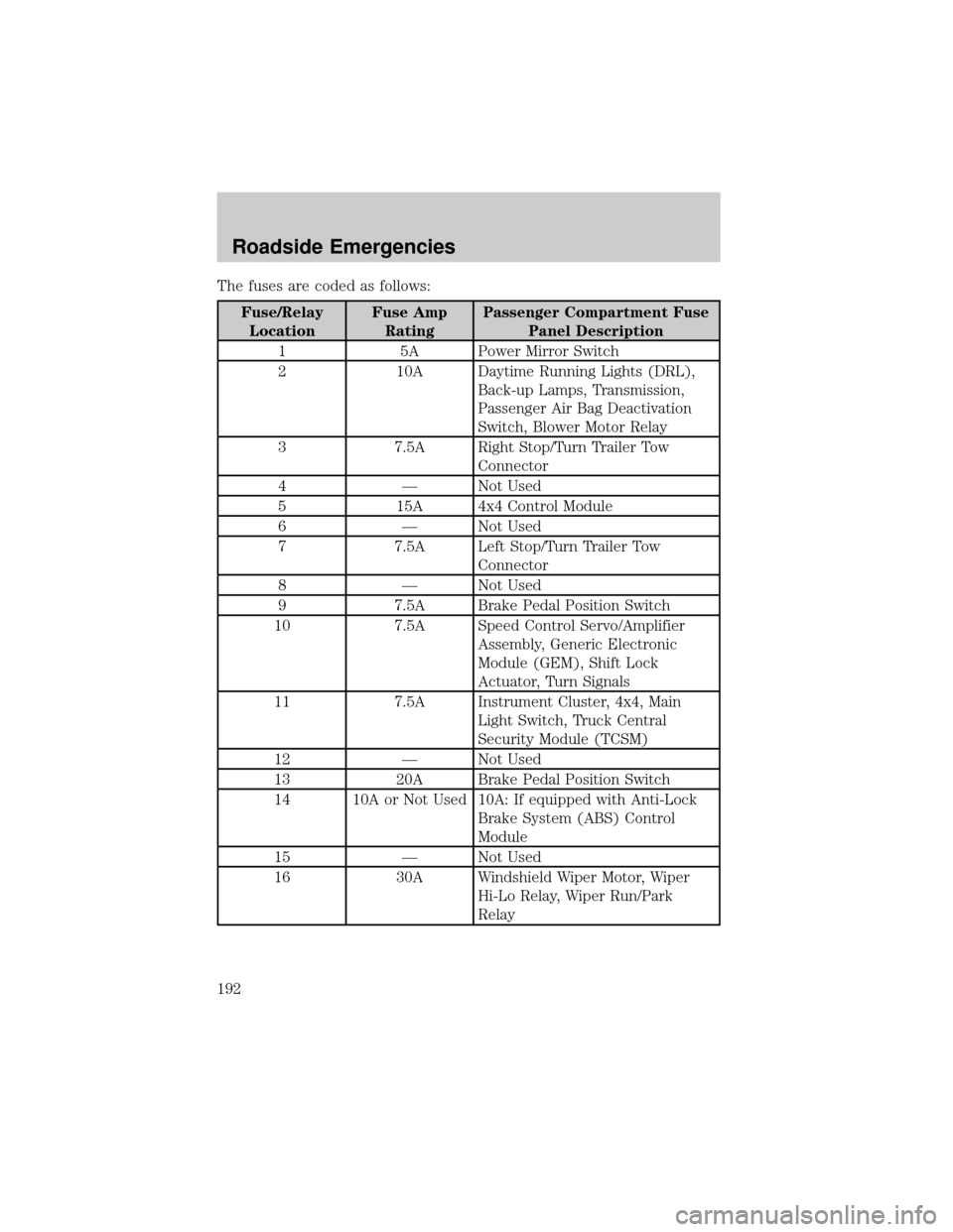
The fuses are coded as follows:
Fuse/Relay
LocationFuse Amp
RatingPassenger Compartment Fuse
Panel Description
1 5A Power Mirror Switch
2 10A Daytime Running Lights (DRL),
Back-up Lamps, Transmission,
Passenger Air Bag Deactivation
Switch, Blower Motor Relay
3 7.5A Right Stop/Turn Trailer Tow
Connector
4 Ð Not Used
5 15A 4x4 Control Module
6 Ð Not Used
7 7.5A Left Stop/Turn Trailer Tow
Connector
8 Ð Not Used
9 7.5A Brake Pedal Position Switch
10 7.5A Speed Control Servo/Amplifier
Assembly, Generic Electronic
Module (GEM), Shift Lock
Actuator, Turn Signals
11 7.5A Instrument Cluster, 4x4, Main
Light Switch, Truck Central
Security Module (TCSM)
12 Ð Not Used
13 20A Brake Pedal Position Switch
14 10A or Not Used 10A: If equipped with Anti-Lock
Brake System (ABS) Control
Module
15 Ð Not Used
16 30A Windshield Wiper Motor, Wiper
Hi-Lo Relay, Wiper Run/Park
Relay
Roadside Emergencies
192
Page 195 of 288
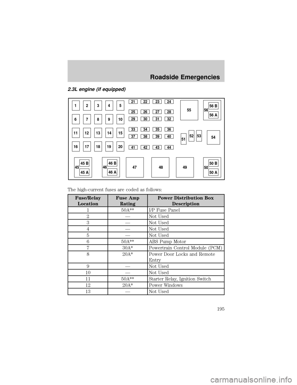
2.3L engine (if equipped)
The high-current fuses are coded as follows:
Fuse/Relay
LocationFuse Amp
RatingPower Distribution Box
Description
1 50A** I/P Fuse Panel
2 Ð Not Used
3 Ð Not Used
4 Ð Not Used
5 Ð Not Used
6 50A** ABS Pump Motor
7 30A* Powertrain Control Module (PCM)
8 20A* Power Door Locks and Remote
Entry
9 Ð Not Used
10 Ð Not Used
11 50A** Starter Relay, Ignition Switch
12 20A* Power Windows
13 Ð Not Used
1234521 22 23 24
25 26 27 28
29 30 31 32
33 34 35 36
37 38 39 40
41 42 43 44
67891055
49 4854 53 52
515656 B
56 A
5050 B
50 A 47 4545 B
45 A
4646 B
46 A 11 12 13 14 15
16 17 18 19 20
Roadside Emergencies
195
Page 196 of 288
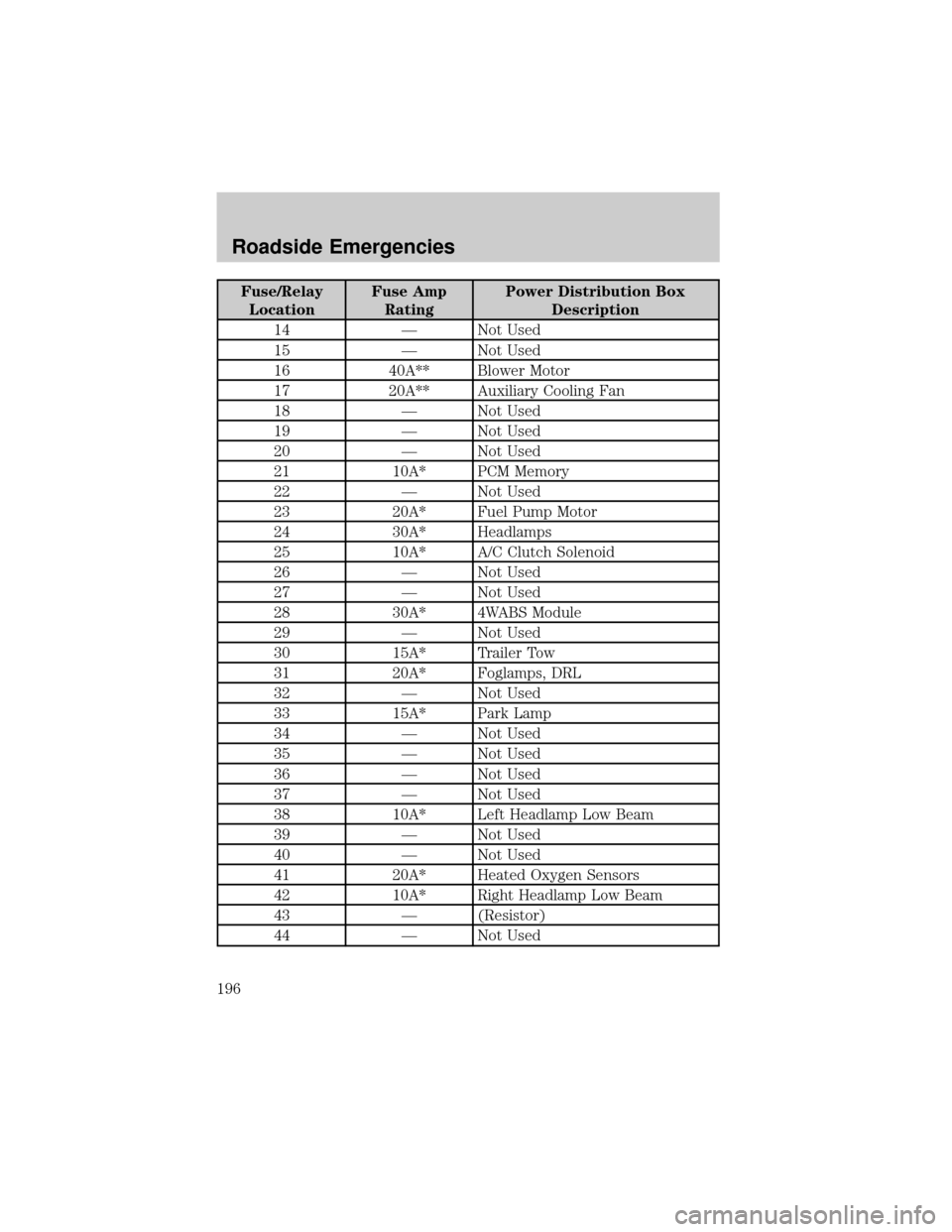
Fuse/Relay
LocationFuse Amp
RatingPower Distribution Box
Description
14 Ð Not Used
15 Ð Not Used
16 40A** Blower Motor
17 20A** Auxiliary Cooling Fan
18 Ð Not Used
19 Ð Not Used
20 Ð Not Used
21 10A* PCM Memory
22 Ð Not Used
23 20A* Fuel Pump Motor
24 30A* Headlamps
25 10A* A/C Clutch Solenoid
26 Ð Not Used
27 Ð Not Used
28 30A* 4WABS Module
29 Ð Not Used
30 15A* Trailer Tow
31 20A* Foglamps, DRL
32 Ð Not Used
33 15A* Park Lamp
34 Ð Not Used
35 Ð Not Used
36 Ð Not Used
37 Ð Not Used
38 10A* Left Headlamp Low Beam
39 Ð Not Used
40 Ð Not Used
41 20A* Heated Oxygen Sensors
42 10A* Right Headlamp Low Beam
43 Ð (Resistor)
44 Ð Not Used
Roadside Emergencies
196
Page 198 of 288
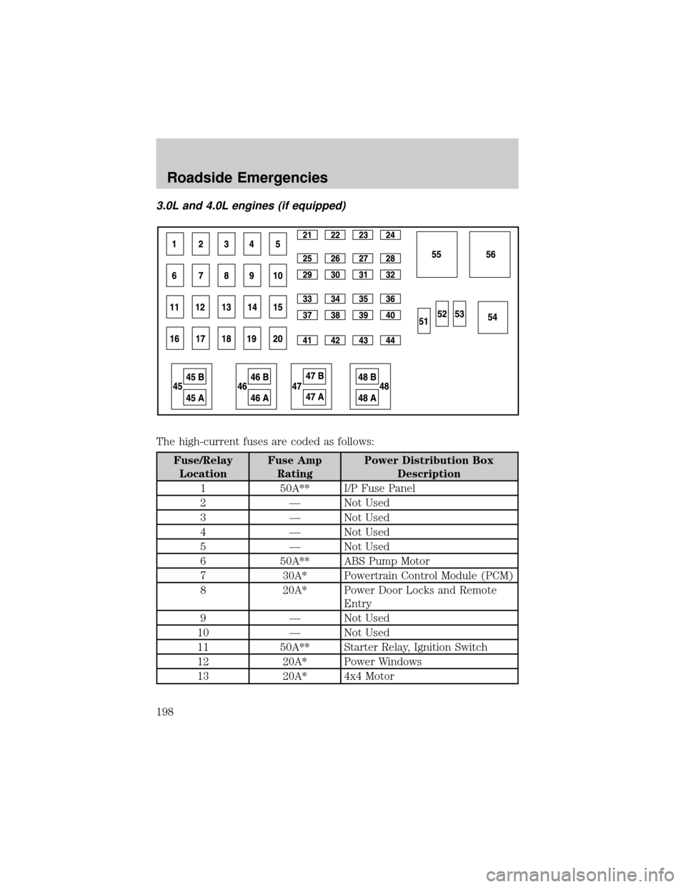
3.0L and 4.0L engines (if equipped)
The high-current fuses are coded as follows:
Fuse/Relay
LocationFuse Amp
RatingPower Distribution Box
Description
1 50A** I/P Fuse Panel
2 Ð Not Used
3 Ð Not Used
4 Ð Not Used
5 Ð Not Used
6 50A** ABS Pump Motor
7 30A* Powertrain Control Module (PCM)
8 20A* Power Door Locks and Remote
Entry
9 Ð Not Used
10 Ð Not Used
11 50A** Starter Relay, Ignition Switch
12 20A* Power Windows
13 20A* 4x4 Motor
Roadside Emergencies
198