jacking points FORD SIERRA 1983 1.G Braking System Workshop Manual
[x] Cancel search | Manufacturer: FORD, Model Year: 1983, Model line: SIERRA, Model: FORD SIERRA 1983 1.GPages: 22, PDF Size: 1.11 MB
Page 5 of 22
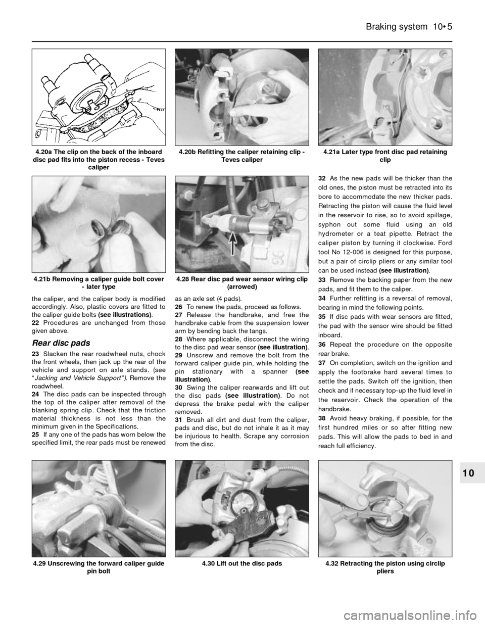
the caliper, and the caliper body is modified
accordingly. Also, plastic covers are fitted to
the caliper guide bolts (see illustrations).
22Procedures are unchanged from those
given above.
Rear disc pads
23Slacken the rear roadwheel nuts, chock
the front wheels, then jack up the rear of the
vehicle and support on axle stands. (see
“Jacking and Vehicle Support”). Remove the
roadwheel.
24The disc pads can be inspected through
the top of the caliper after removal of the
blanking spring clip. Check that the friction
material thickness is not less than the
minimum given in the Specifications.
25If any one of the pads has worn below the
specified limit, the rear pads must be renewedas an axle set (4 pads).
26To renew the pads, proceed as follows.
27Release the handbrake, and free the
handbrake cable from the suspension lower
arm by bending back the tangs.
28Where applicable, disconnect the wiring
to the disc pad wear sensor (see illustration).
29Unscrew and remove the bolt from the
forward caliper guide pin, while holding the
pin stationary with a spanner (see
illustration).
30Swing the caliper rearwards and lift out
the disc pads (see illustration). Do not
depress the brake pedal with the caliper
removed.
31Brush all dirt and dust from the caliper,
pads and disc, but do not inhale it as it may
be injurious to health. Scrape any corrosion
from the disc.32As the new pads will be thicker than the
old ones, the piston must be retracted into its
bore to accommodate the new thicker pads.
Retracting the piston will cause the fluid level
in the reservoir to rise, so to avoid spillage,
syphon out some fluid using an old
hydrometer or a teat pipette. Retract the
caliper piston by turning it clockwise. Ford
tool No 12-006 is designed for this purpose,
but a pair of circlip pliers or any similar tool
can be used instead (see illustration).
33Remove the backing paper from the new
pads, and fit them to the caliper.
34Further refitting is a reversal of removal,
bearing in mind the following points.
35If disc pads with wear sensors are fitted,
the pad with the sensor wire should be fitted
inboard.
36Repeat the procedure on the opposite
rear brake.
37On completion, switch on the ignition and
apply the footbrake hard several times to
settle the pads. Switch off the ignition, then
check and if necessary top-up the fluid level in
the reservoir. Check the operation of the
handbrake.
38Avoid heavy braking, if possible, for the
first hundred miles or so after fitting new
pads. This will allow the pads to bed in and
reach full efficiency.
Braking system 10•5
10
4.21a Later type front disc pad retaining
clip
4.32 Retracting the piston using circlip
pliers4.30 Lift out the disc pads
4.28 Rear disc pad wear sensor wiring clip
(arrowed)
4.29 Unscrewing the forward caliper guide
pin bolt
4.21b Removing a caliper guide bolt cover
- later type
4.20b Refitting the caliper retaining clip -
Teves caliper4.20a The clip on the back of the inboard
disc pad fits into the piston recess - Teves
caliper
Page 6 of 22
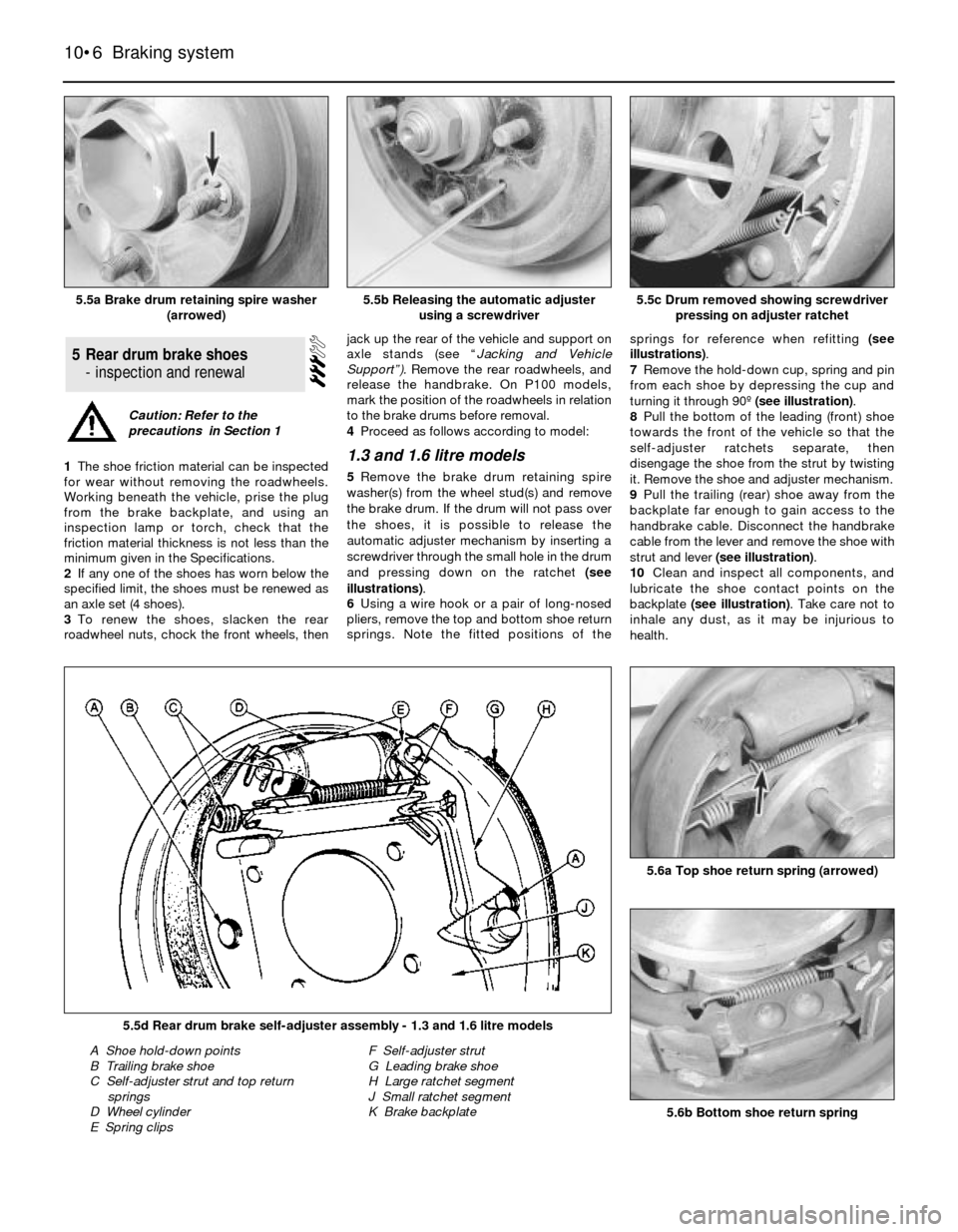
1The shoe friction material can be inspected
for wear without removing the roadwheels.
Working beneath the vehicle, prise the plug
from the brake backplate, and using an
inspection lamp or torch, check that the
friction material thickness is not less than the
minimum given in the Specifications.
2If any one of the shoes has worn below the
specified limit, the shoes must be renewed as
an axle set (4 shoes).
3To renew the shoes, slacken the rear
roadwheel nuts, chock the front wheels, thenjack up the rear of the vehicle and support on
axle stands (see “Jacking and Vehicle
Support”).Remove the rear roadwheels, and
release the handbrake. On P100 models,
mark the position of the roadwheels in relation
to the brake drums before removal.
4Proceed as follows according to model:1.3 and 1.6 litre models
5Remove the brake drum retaining spire
washer(s) from the wheel stud(s) and remove
the brake drum. If the drum will not pass over
the shoes, it is possible to release the
automatic adjuster mechanism by inserting a
screwdriver through the small hole in the drum
and pressing down on the ratchet (see
illustrations).
6Using a wire hook or a pair of long-nosed
pliers, remove the top and bottom shoe return
springs. Note the fitted positions of thesprings for reference when refitting (see
illustrations).
7Remove the hold-down cup, spring and pin
from each shoe by depressing the cup and
turning it through 90º (see illustration).
8Pull the bottom of the leading (front) shoe
towards the front of the vehicle so that the
self-adjuster ratchets separate, then
disengage the shoe from the strut by twisting
it. Remove the shoe and adjuster mechanism.
9Pull the trailing (rear) shoe away from the
backplate far enough to gain access to the
handbrake cable. Disconnect the handbrake
cable from the lever and remove the shoe with
strut and lever (see illustration).
10Clean and inspect all components, and
lubricate the shoe contact points on the
backplate (see illustration). Take care not to
inhale any dust, as it may be injurious to
health.
5Rear drum brake shoes
- inspection and renewal
10•6Braking system
5.5a Brake drum retaining spire washer
(arrowed)5.5c Drum removed showing screwdriver
pressing on adjuster ratchet
5.6b Bottom shoe return spring
5.6a Top shoe return spring (arrowed)
5.5d Rear drum brake self-adjuster assembly - 1.3 and 1.6 litre models
A Shoe hold-down points
B Trailing brake shoe
C Self-adjuster strut and top return
springs
D Wheel cylinder
E Spring clipsF Self-adjuster strut
G Leading brake shoe
H Large ratchet segment
J Small ratchet segment
K Brake backplate
5.5b Releasing the automatic adjuster
using a screwdriver
Caution: Refer to the
precautions in Section 1
Page 8 of 22
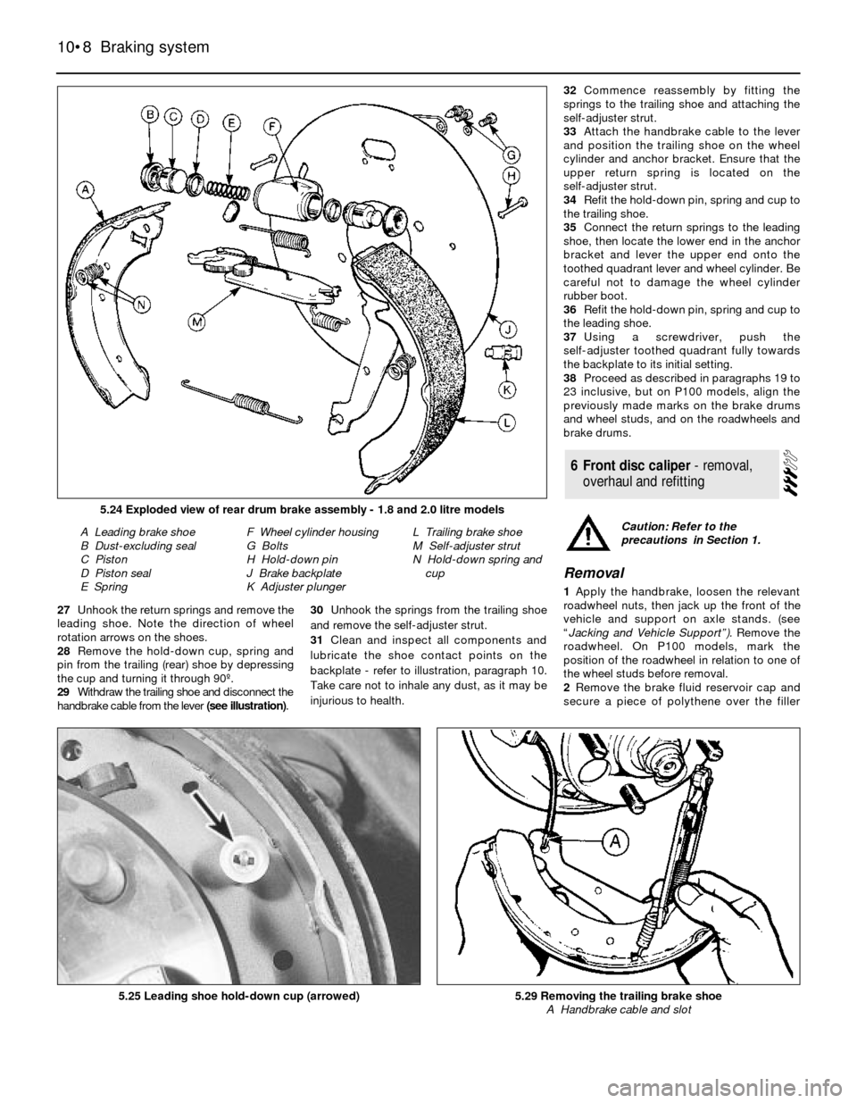
27Unhook the return springs and remove the
leading shoe. Note the direction of wheel
rotation arrows on the shoes.
28Remove the hold-down cup, spring and
pin from the trailing (rear) shoe by depressing
the cup and turning it through 90º.
29Withdraw the trailing shoe and disconnect the
handbrake cable from the lever (see illustration).30Unhook the springs from the trailing shoe
and remove the self-adjuster strut.
31Clean and inspect all components and
lubricate the shoe contact points on the
backplate - refer to illustration, paragraph 10.
Take care not to inhale any dust, as it may be
injurious to health.32Commence reassembly by fitting the
springs to the trailing shoe and attaching the
self-adjuster strut.
33Attach the handbrake cable to the lever
and position the trailing shoe on the wheel
cylinder and anchor bracket. Ensure that the
upper return spring is located on the
self-adjuster strut.
34Refit the hold-down pin, spring and cup to
the trailing shoe.
35Connect the return springs to the leading
shoe, then locate the lower end in the anchor
bracket and lever the upper end onto the
toothed quadrant lever and wheel cylinder. Be
careful not to damage the wheel cylinder
rubber boot.
36Refit the hold-down pin, spring and cup to
the leading shoe.
37Using a screwdriver, push the
self-adjuster toothed quadrant fully towards
the backplate to its initial setting.
38Proceed as described in paragraphs 19 to
23 inclusive, but on P100 models, align the
previously made marks on the brake drums
and wheel studs, and on the roadwheels and
brake drums.
Removal
1Apply the handbrake, loosen the relevant
roadwheel nuts, then jack up the front of the
vehicle and support on axle stands. (see
“Jacking and Vehicle Support”). Remove the
roadwheel. On P100 models, mark the
position of the roadwheel in relation to one of
the wheel studs before removal.
2Remove the brake fluid reservoir cap and
secure a piece of polythene over the filler
6Front disc caliper - removal,
overhaul and refitting
10•8Braking system
5.24 Exploded view of rear drum brake assembly - 1.8 and 2.0 litre models
A Leading brake shoe
B Dust-excluding seal
C Piston
D Piston seal
E SpringF Wheel cylinder housing
G Bolts
H Hold-down pin
J Brake backplate
K Adjuster plungerL Trailing brake shoe
M Self-adjuster strut
N Hold-down spring and
cup
5.25 Leading shoe hold-down cup (arrowed)5.29 Removing the trailing brake shoe
A Handbrake cable and slot
Caution: Refer to the
precautions in Section 1.
Page 13 of 22
3Remove the wheel cylinder.
4Remove the driveshaft but do not refit the
securing bolts to the backplate.
5Remove the backplate.
6If required, prise out the handbrake stop
button.
7Refitting is a reversal of removal.
P 100 models
Note: When refitting the backplate, a new rear
hub nut and driveshaft O-ring must be used.
8Proceed as described in paragraphs 1 to 3
inclusive.
9Remove the driveshaft.
10Relieve the staking on the rear hub nut,
and using a 50 mm socket and a suitable
extension bar, unscrew the nut. Note that the
nut is extremely tight.
11Pull off the hub.
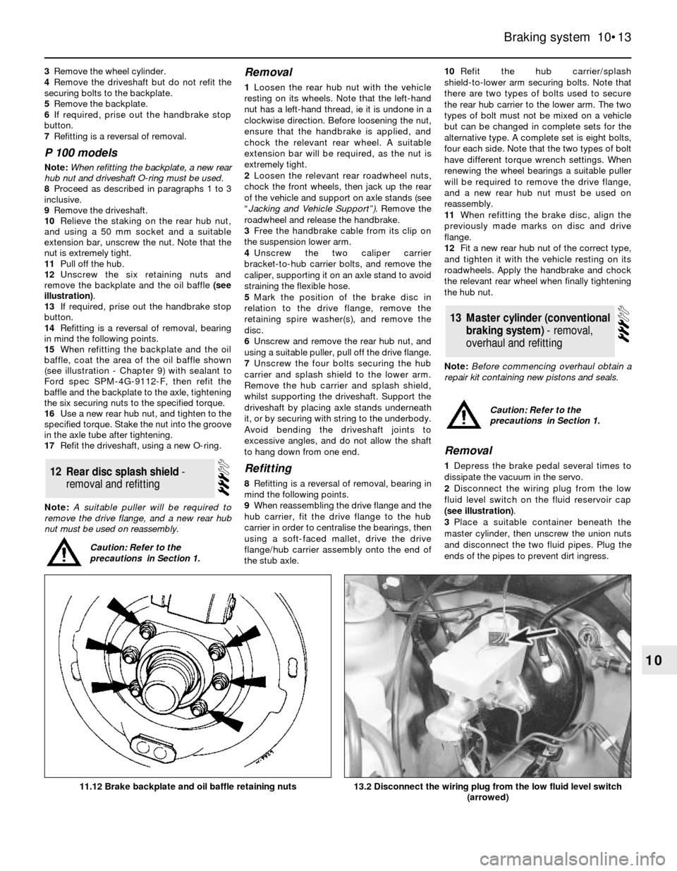
12Unscrew the six retaining nuts and
remove the backplate and the oil baffle (see
illustration).
13If required, prise out the handbrake stop
button.
14Refitting is a reversal of removal, bearing
in mind the following points.
15When refitting the backplate and the oil
baffle, coat the area of the oil baffle shown
(see illustration - Chapter 9) with sealant to
Ford spec SPM-4G-9112-F, then refit the
baffle and the backplate to the axle, tightening
the six securing nuts to the specified torque.
16Use a new rear hub nut, and tighten to the
specified torque. Stake the nut into the groove
in the axle tube after tightening.
17Refit the driveshaft, using a new O-ring.
Note: A suitable puller will be required to
remove the drive flange, and a new rear hub
nut must be used on reassembly.
Removal
1Loosen the rear hub nut with the vehicle
resting on its wheels. Note that the left-hand
nut has a left-hand thread, ie it is undone in a
clockwise direction. Before loosening the nut,
ensure that the handbrake is applied, and
chock the relevant rear wheel. A suitable
extension bar will be required, as the nut is
extremely tight.
2Loosen the relevant rear roadwheel nuts,
chock the front wheels, then jack up the rear
of the vehicle and support on axle stands (see
“Jacking and Vehicle Support”).Remove the
roadwheel and release the handbrake.
3Free the handbrake cable from its clip on
the suspension lower arm.
4Unscrew the two caliper carrier
bracket-to-hub carrier bolts, and remove the
caliper, supporting it on an axle stand to avoid
straining the flexible hose.
5Mark the position of the brake disc in
relation to the drive flange, remove the
retaining spire washer(s), and remove the
disc.
6Unscrew and remove the rear hub nut, and
using a suitable puller, pull off the drive flange.
7Unscrew the four bolts securing the hub
carrier and splash shield to the lower arm.
Remove the hub carrier and splash shield,
whilst supporting the driveshaft. Support the
driveshaft by placing axle stands underneath
it, or by securing with string to the underbody.
Avoid bending the driveshaft joints to
excessive angles, and do not allow the shaft
to hang down from one end.
Refitting
8Refitting is a reversal of removal, bearing in
mind the following points.
9When reassembling the drive flange and the
hub carrier, fit the drive flange to the hub
carrier in order to centralise the bearings, then
using a soft-faced mallet, drive the drive
flange/hub carrier assembly onto the end of
the stub axle.10Refit the hub carrier/splash
shield-to-lower arm securing bolts. Note that
there are two types of bolts used to secure
the rear hub carrier to the lower arm. The two
types of bolt must not be mixed on a vehicle
but can be changed in complete sets for the
alternative type. A complete set is eight bolts,
four each side. Note that the two types of bolt
have different torque wrench settings. When
renewing the wheel bearings a suitable puller
will be required to remove the drive flange,
and a new rear hub nut must be used on
reassembly.
11When refitting the brake disc, align the
previously made marks on disc and drive
flange.
12Fit a new rear hub nut of the correct type,
and tighten it with the vehicle resting on its
roadwheels. Apply the handbrake and chock
the relevant rear wheel when finally tightening
the hub nut.
Note: Before commencing overhaul obtain a
repair kit containing new pistons and seals.
Removal
1Depress the brake pedal several times to
dissipate the vacuum in the servo.
2Disconnect the wiring plug from the low
fluid level switch on the fluid reservoir cap
(see illustration).
3Place a suitable container beneath the
master cylinder, then unscrew the union nuts
and disconnect the two fluid pipes. Plug the
ends of the pipes to prevent dirt ingress.
13Master cylinder (conventional
braking system) - removal,
overhaul and refitting
12Rear disc splash shield -
removal and refitting
Braking system 10•13
10
13.2 Disconnect the wiring plug from the low fluid level switch
(arrowed)11.12 Brake backplate and oil baffle retaining nuts
Caution: Refer to the
precautions in Section 1.
Caution: Refer to the
precautions in Section 1.
Page 18 of 22
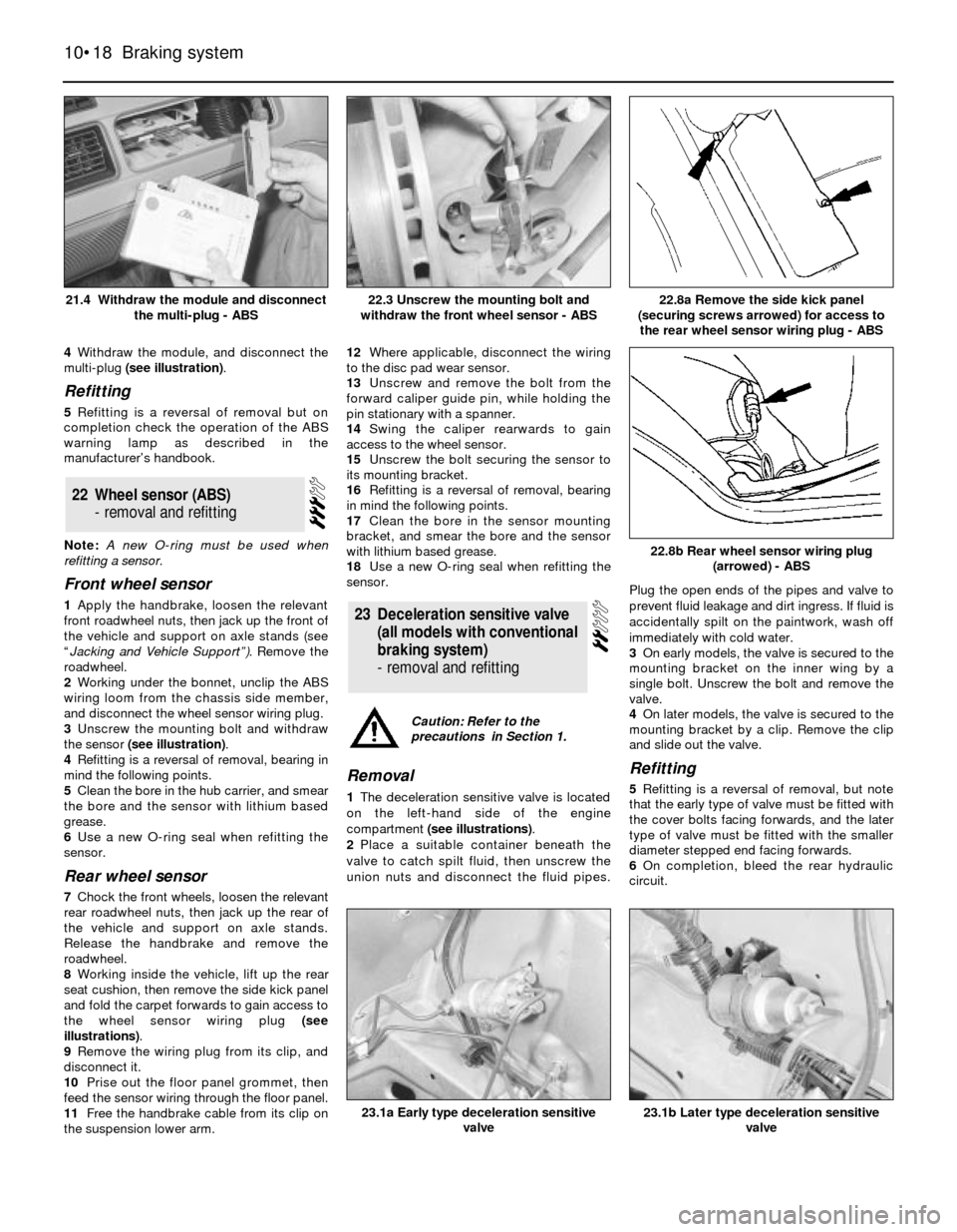
4Withdraw the module, and disconnect the
multi-plug (see illustration).
Refitting
5Refitting is a reversal of removal but on
completion check the operation of the ABS
warning lamp as described in the
manufacturer’s handbook.
Note: A new O-ring must be used when
refitting a sensor.
Front wheel sensor
1Apply the handbrake, loosen the relevant
front roadwheel nuts, then jack up the front of
the vehicle and support on axle stands (see
“Jacking and Vehicle Support”). Remove the
roadwheel.
2Working under the bonnet, unclip the ABS
wiring loom from the chassis side member,
and disconnect the wheel sensor wiring plug.
3Unscrew the mounting bolt and withdraw
the sensor (see illustration).
4Refitting is a reversal of removal, bearing in
mind the following points.
5Clean the bore in the hub carrier, and smear
the bore and the sensor with lithium based
grease.
6Use a new O-ring seal when refitting the
sensor.
Rear wheel sensor
7Chock the front wheels, loosen the relevant
rear roadwheel nuts, then jack up the rear of
the vehicle and support on axle stands.
Release the handbrake and remove the
roadwheel.
8Working inside the vehicle, lift up the rear
seat cushion, then remove the side kick panel
and fold the carpet forwards to gain access to
the wheel sensor wiring plug (see
illustrations).
9Remove the wiring plug from its clip, and
disconnect it.
10Prise out the floor panel grommet, then
feed the sensor wiring through the floor panel.
11Free the handbrake cable from its clip on
the suspension lower arm.12Where applicable, disconnect the wiring
to the disc pad wear sensor.
13Unscrew and remove the bolt from the
forward caliper guide pin, while holding the
pin stationary with a spanner.
14Swing the caliper rearwards to gain
access to the wheel sensor.
15Unscrew the bolt securing the sensor to
its mounting bracket.
16Refitting is a reversal of removal, bearing
in mind the following points.
17Clean the bore in the sensor mounting
bracket, and smear the bore and the sensor
with lithium based grease.
18Use a new O-ring seal when refitting the
sensor.
Removal
1The deceleration sensitive valve is located
on the left-hand side of the engine
compartment (see illustrations).
2Place a suitable container beneath the
valve to catch spilt fluid, then unscrew the
union nuts and disconnect the fluid pipes.Plug the open ends of the pipes and valve to
prevent fluid leakage and dirt ingress. If fluid is
accidentally spilt on the paintwork, wash off
immediately with cold water.
3On early models, the valve is secured to the
mounting bracket on the inner wing by a
single bolt. Unscrew the bolt and remove the
valve.
4On later models, the valve is secured to the
mounting bracket by a clip. Remove the clip
and slide out the valve.
Refitting
5Refitting is a reversal of removal, but note
that the early type of valve must be fitted with
the cover bolts facing forwards, and the later
type of valve must be fitted with the smaller
diameter stepped end facing forwards.
6On completion, bleed the rear hydraulic
circuit.
23Deceleration sensitive valve
(all models with conventional
braking system)
- removal and refitting
22Wheel sensor (ABS)
- removal and refitting
10•18Braking system
21.4 Withdraw the module and disconnect
the multi-plug - ABS22.8a Remove the side kick panel
(securing screws arrowed) for access to
the rear wheel sensor wiring plug - ABS
23.1b Later type deceleration sensitive
valve23.1a Early type deceleration sensitive
valve
22.8b Rear wheel sensor wiring plug
(arrowed) - ABS
22.3 Unscrew the mounting bolt and
withdraw the front wheel sensor - ABS
Caution: Refer to the
precautions in Section 1.