heater FORD SIERRA 1983 1.G DOHC Engine Workshop Manual
[x] Cancel search | Manufacturer: FORD, Model Year: 1983, Model line: SIERRA, Model: FORD SIERRA 1983 1.GPages: 18, PDF Size: 0.9 MB
Page 4 of 18

Note:A hoist and lifting tackle will be
required.
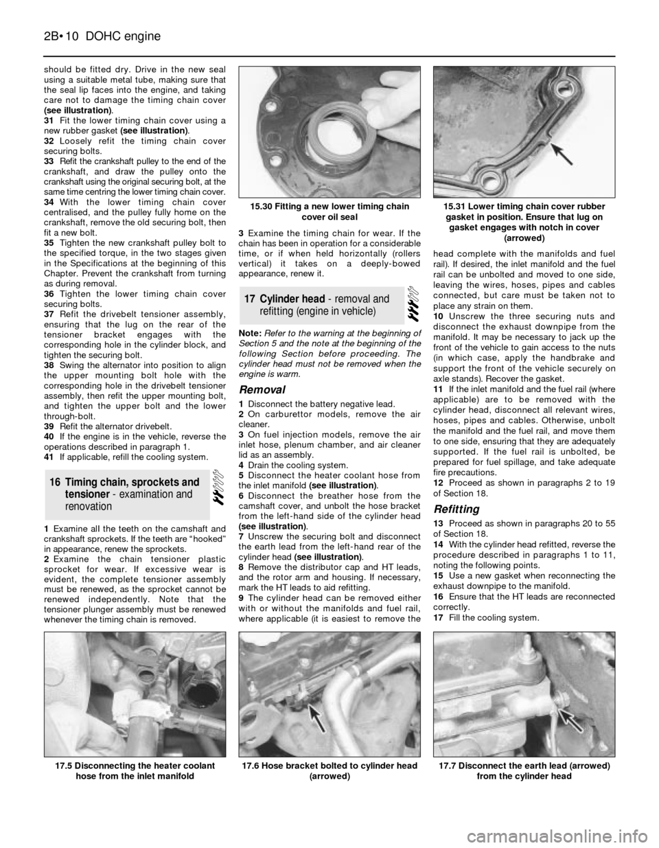
1Disconnect the battery negative lead.
2Remove the bonnet.
3On carburettor models, remove the air
cleaner.
4On fuel injection models, remove the air
inlet hose, plenum chamber, and air cleaner
lid as an assembly.
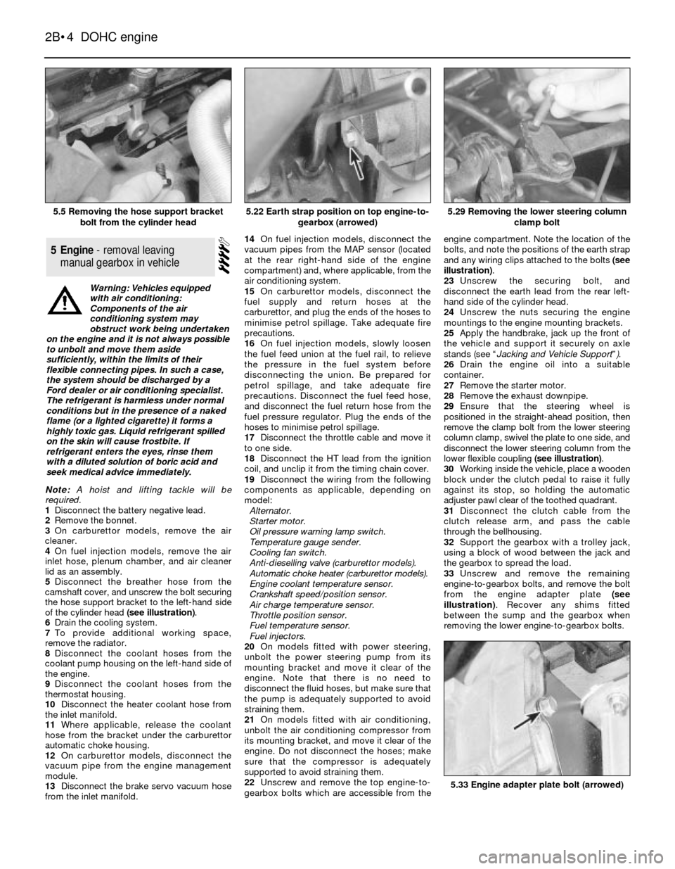
5Disconnect the breather hose from the
camshaft cover, and unscrew the bolt securing
the hose support bracket to the left-hand side
of the cylinder head (see illustration).
6Drain the cooling system.
7To provide additional working space,
remove the radiator.
8Disconnect the coolant hoses from the
coolant pump housing on the left-hand side of
the engine.
9Disconnect the coolant hoses from the
thermostat housing.
10Disconnect the heater coolant hose from
the inlet manifold.
11Where applicable, release the coolant
hose from the bracket under the carburettor
automatic choke housing.
12On carburettor models, disconnect the
vacuum pipe from the engine management
module.
13Disconnect the brake servo vacuum hose
from the inlet manifold.14On fuel injection models, disconnect the
vacuum pipes from the MAP sensor (located
at the rear right-hand side of the engine
compartment) and, where applicable, from the
air conditioning system.
15On carburettor models, disconnect the
fuel supply and return hoses at the
carburettor, and plug the ends of the hoses to
minimise petrol spillage. Take adequate fire
precautions.
16On fuel injection models, slowly loosen
the fuel feed union at the fuel rail, to relieve
the pressure in the fuel system before
disconnecting the union. Be prepared for
petrol spillage, and take adequate fire
precautions. Disconnect the fuel feed hose,
and disconnect the fuel return hose from the
fuel pressure regulator. Plug the ends of the
hoses to minimise petrol spillage.
17Disconnect the throttle cable and move it
to one side.
18Disconnect the HT lead from the ignition
coil, and unclip it from the timing chain cover.
19Disconnect the wiring from the following
components as applicable, depending on
model:
Alternator.
Starter motor.
Oil pressure warning lamp switch.
Temperature gauge sender.
Cooling fan switch.
Anti-dieselling valve (carburettor models).
Automatic choke heater (carburettor models).
Engine coolant temperature sensor.
Crankshaft speed/position sensor.
Air charge temperature sensor.
Throttle position sensor.
Fuel temperature sensor.
Fuel injectors.
20On models fitted with power steering,
unbolt the power steering pump from its
mounting bracket and move it clear of the
engine. Note that there is no need to
disconnect the fluid hoses, but make sure that
the pump is adequately supported to avoid
straining them.
21On models fitted with air conditioning,
unbolt the air conditioning compressor from
its mounting bracket, and move it clear of the
engine. Do not disconnect the hoses; make
sure that the compressor is adequately
supported to avoid straining them.
22Unscrew and remove the top engine-to-
gearbox bolts which are accessible from theengine compartment. Note the location of the
bolts, and note the positions of the earth strap
and any wiring clips attached to the bolts (see
illustration).
23Unscrew the securing bolt, and
disconnect the earth lead from the rear left-
hand side of the cylinder head.
24Unscrew the nuts securing the engine
mountings to the engine mounting brackets.
25Apply the handbrake, jack up the front of
the vehicle and support it securely on axle
stands (see “Jacking and Vehicle Support”).
26Drain the engine oil into a suitable
container.
27Remove the starter motor.
28Remove the exhaust downpipe.
29Ensure that the steering wheel is
positioned in the straight-ahead position, then
remove the clamp bolt from the lower steering
column clamp, swivel the plate to one side, and
disconnect the lower steering column from the
lower flexible coupling (see illustration).
30Working inside the vehicle, place a wooden
block under the clutch pedal to raise it fully
against its stop, so holding the automatic
adjuster pawl clear of the toothed quadrant.
31Disconnect the clutch cable from the
clutch release arm, and pass the cable
through the bellhousing.
32Support the gearbox with a trolley jack,
using a block of wood between the jack and
the gearbox to spread the load.
33Unscrew and remove the remaining
engine-to-gearbox bolts, and remove the bolt
from the engine adapter plate (see
illustration). Recover any shims fitted
between the sump and the gearbox when
removing the lower engine-to-gearbox bolts.
5Engine - removal leaving
manual gearbox in vehicle
2B•4DOHC engine
5.5 Removing the hose support bracket
bolt from the cylinder head5.29 Removing the lower steering column
clamp bolt
5.33 Engine adapter plate bolt (arrowed)
5.22 Earth strap position on top engine-to-
gearbox (arrowed)
Warning: Vehicles equipped
with air conditioning:
Components of the air
conditioning system may
obstruct work being undertaken
on the engine and it is not always possible
to unbolt and move them aside
sufficiently, within the limits of their
flexible connecting pipes. In such a case,
the system should be discharged by a
Ford dealer or air conditioning specialist.
The refrigerant is harmless under normal
conditions but in the presence of a naked
flame (or a lighted cigarette) it forms a
highly toxic gas. Liquid refrigerant spilled
on the skin will cause frostbite. If
refrigerant enters the eyes, rinse them
with a diluted solution of boric acid and
seek medical advice immediately.
Page 10 of 18

should be fitted dry. Drive in the new seal
using a suitable metal tube, making sure that
the seal lip faces into the engine, and taking
care not to damage the timing chain cover
(see illustration).
31Fit the lower timing chain cover using a
new rubber gasket (see illustration).
32Loosely refit the timing chain cover
securing bolts.
33Refit the crankshaft pulley to the end of the
crankshaft, and draw the pulley onto the
crankshaft using the original securing bolt, at the
same time centring the lower timing chain cover.
34With the lower timing chain cover
centralised, and the pulley fully home on the
crankshaft, remove the old securing bolt, then
fit a new bolt.
35Tighten the new crankshaft pulley bolt to
the specified torque, in the two stages given
in the Specifications at the beginning of this
Chapter. Prevent the crankshaft from turning
as during removal.
36Tighten the lower timing chain cover
securing bolts.
37Refit the drivebelt tensioner assembly,
ensuring that the lug on the rear of the
tensioner bracket engages with the
corresponding hole in the cylinder block, and
tighten the securing bolt.
38Swing the alternator into position to align
the upper mounting bolt hole with the
corresponding hole in the drivebelt tensioner
assembly, then refit the upper mounting bolt,
and tighten the upper bolt and the lower
through-bolt.
39Refit the alternator drivebelt.
40If the engine is in the vehicle, reverse the
operations described in paragraph 1.
41If applicable, refill the cooling system.
1Examine alI the teeth on the camshaft and
crankshaft sprockets. If the teeth are “hooked”
in appearance, renew the sprockets.
2Examine the chain tensioner plastic
sprocket for wear. If excessive wear is
evident, the complete tensioner assembly
must be renewed, as the sprocket cannot be
renewed independently. Note that the
tensioner plunger assembly must be renewed
whenever the timing chain is removed.3Examine the timing chain for wear. If the
chain has been in operation for a considerable
time, or if when held horizontally (rollers
vertical) it takes on a deeply-bowed
appearance, renew it.
Note: Refer to the warning at the beginning of
Section 5 and the note at the beginning of the
following Section before proceeding. The
cylinder head must not be removed when the
engine is warm.
Removal
1Disconnect the battery negative lead.
2On carburettor models, remove the air
cleaner.
3On fuel injection models, remove the air
inlet hose, plenum chamber, and air cleaner
lid as an assembly.
4Drain the cooling system.
5Disconnect the heater coolant hose from
the inlet manifold (see illustration).
6Disconnect the breather hose from the
camshaft cover, and unbolt the hose bracket
from the left-hand side of the cylinder head
(see illustration).
7Unscrew the securing bolt and disconnect
the earth lead from the left-hand rear of the
cylinder head (see illustration).
8Remove the distributor cap and HT leads,
and the rotor arm and housing. If necessary,
mark the HT leads to aid refitting.
9The cylinder head can be removed either
with or without the manifolds and fuel rail,
where applicable (it is easiest to remove thehead complete with the manifolds and fuel
rail). If desired, the inlet manifold and the fuel
rail can be unbolted and moved to one side,
leaving the wires, hoses, pipes and cables
connected, but care must be taken not to
place any strain on them.
10Unscrew the three securing nuts and
disconnect the exhaust downpipe from the
manifold. It may be necessary to jack up the
front of the vehicle to gain access to the nuts
(in which case, apply the handbrake and
support the front of the vehicle securely on
axle stands). Recover the gasket.
11If the inlet manifold and the fuel rail (where
applicable) are to be removed with the
cylinder head, disconnect all relevant wires,
hoses, pipes and cables. Otherwise, unbolt
the manifold and the fuel rail, and move them
to one side, ensuring that they are adequately
supported. If the fuel rail is unbolted, be
prepared for fuel spillage, and take adequate
fire precautions.
12Proceed as shown in paragraphs 2 to 19
of Section 18.
Refitting
13Proceed as shown in paragraphs 20 to 55
of Section 18.
14With the cylinder head refitted, reverse the
procedure described in paragraphs 1 to 11,
noting the following points.
15Use a new gasket when reconnecting the
exhaust downpipe to the manifold.
16Ensure that the HT leads are reconnected
correctly.
17Fill the cooling system.
17Cylinder head - removal and
refitting (engine in vehicle)
16Timing chain, sprockets and
tensioner - examination and
renovation
2B•10DOHC engine
15.30 Fitting a new lower timing chain
cover oil seal
17.5 Disconnecting the heater coolant
hose from the inlet manifold17.7 Disconnect the earth lead (arrowed)
from the cylinder head17.6 Hose bracket bolted to cylinder head
(arrowed)
15.31 Lower timing chain cover rubber
gasket in position. Ensure that lug on
gasket engages with notch in cover
(arrowed)