spark plugs FORD SIERRA 1983 1.G DOHC Engine Workshop Manual
[x] Cancel search | Manufacturer: FORD, Model Year: 1983, Model line: SIERRA, Model: FORD SIERRA 1983 1.GPages: 18, PDF Size: 0.9 MB
Page 8 of 18

Dismantling
1Refer to Chapter 2, PartA, Section 18,
paragraphs 1 to 8 inclusive.
2A suitable selection of splined and Torx
sockets will be required to remove many of
the bolts when dismantling the engine.
3Before dismantling the main engine
components, the following externally-
mounted ancillary components can be
removed, with reference to the relevant
Chapters of this Manual and the relevant
Sections of this Chapter, where applicable.
Inlet manifold (and carburettor, if applicable)
Exhaust manifold
Alternator.
Coolant pump, and thermostat
Alternator/coolant pump drivebelt tensioner
Distributor cap, HT leads and spark plugs
Oil pressure warning lamp switch
Crankshaft speed/position sensor
Oil filter
Dipstick
Engine mounting brackets (if not already done)
Crankcase ventilation pipe and hoses
Clutch
Alternator mounting bracket.
Air conditioning compressor mounting
bracket (where applicable).
Engine lifting brackets.
Examination and renovation
4Refer to Chapter 2, PartA, Section 18, but
note that the connecting rod bolts should be
renewed on reassembly, and when renewing
the cylinder head bolts, the latest type bolts
with hexagonal heads should always be used.
Reassembly
5Proceed as described in Chapter 2, PartA,
Section 18, noting the following:
6If they have been removed, new cylinder
head bolts (both M11 and M8, of the latest
type with hexagonal heads), flywheel bolts,
and connecting rod bolts must be used.
Note: Refer to the warning at the beginning of
Section 5 before proceeding. A suitable puller
will be required to remove the crankshaft pulley.
A new crankshaft pulley bolt, a new timing chain
tensioner plunger assembly, new upper and
lower timing chain cover gaskets, and a new
camshaft cover gasket and reinforcing sleeve
sealing rings, must be used on refitting.
Removal
1If the engine is in the car, carry out the
following operations:
a)Disconnect the battery negative lead.
b)To improve access, remove the radiator. It
will be difficult to remove the crankshaft
pulley with the radiator in place.c)On carburettor models, remove the air
cleaner.
d)On fuel injection models, remove the air
inlet hose, plenum chamber, and air
cleaner lid as an assembly.
e)Disconnect the breather hose from the
camshaft cover.
f)Remove the distributor cap and HT leads,
and the rotor arm and housing.
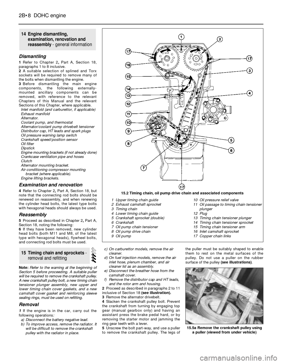
2Proceed as described in paragraphs 2 to 11
inclusive of Section 18 (see illustration).
3Remove the alternator drivebelt.
4Slacken the crankshaft pulley bolt. Prevent
the crankshaft from turning by engaging top
gear (manual gearbox only) and having an
assistant press the brake pedal hard, or by
removing the starter motor and jamming the
ring gear teeth with a lever.
5Unscrew the bolt part-way, and use a puller
to remove the crankshaft pulley. The legs ofthe puller must be suitably shaped to enable
them to rest on the metal surfaces of the
pulley. Do not use a puller on the rubber
surface of the pulley (see illustrations).
15Timing chain and sprockets -
removal and refitting
14Engine dismantling,
examination, renovation and
reassembly - general information
2B•8DOHC engine
15.2 Timing chain, oil pump drive chain and associated components
1 Upper timing chain guide
2 Exhaust camshaft sprocket
3 Timing chain
4 Lower timing chain guide
5 Crankshaft sprocket (double)
6 Crankshaft
7 Oil pump chain tensioner
8 Oil pump drive chain
9 Oil pump10 Oil pressure relief valve
11 Oil passage to timing chain tensioner
plunger
12 Plug
13 Timing chain tensioner plunger
14 Timing chain tensioner sprocket
15 Timing chain tensioner arm
16 Inlet camshaft sprocket
17 Copper chain links
15.5a Remove the crankshaft pulley using
a puller (viewed from under vehicle)