spare wheel FORD SIERRA 1985 1.G DOHC Engine Workshop Manual
[x] Cancel search | Manufacturer: FORD, Model Year: 1985, Model line: SIERRA, Model: FORD SIERRA 1985 1.GPages: 18, PDF Size: 0.9 MB
Page 17 of 18

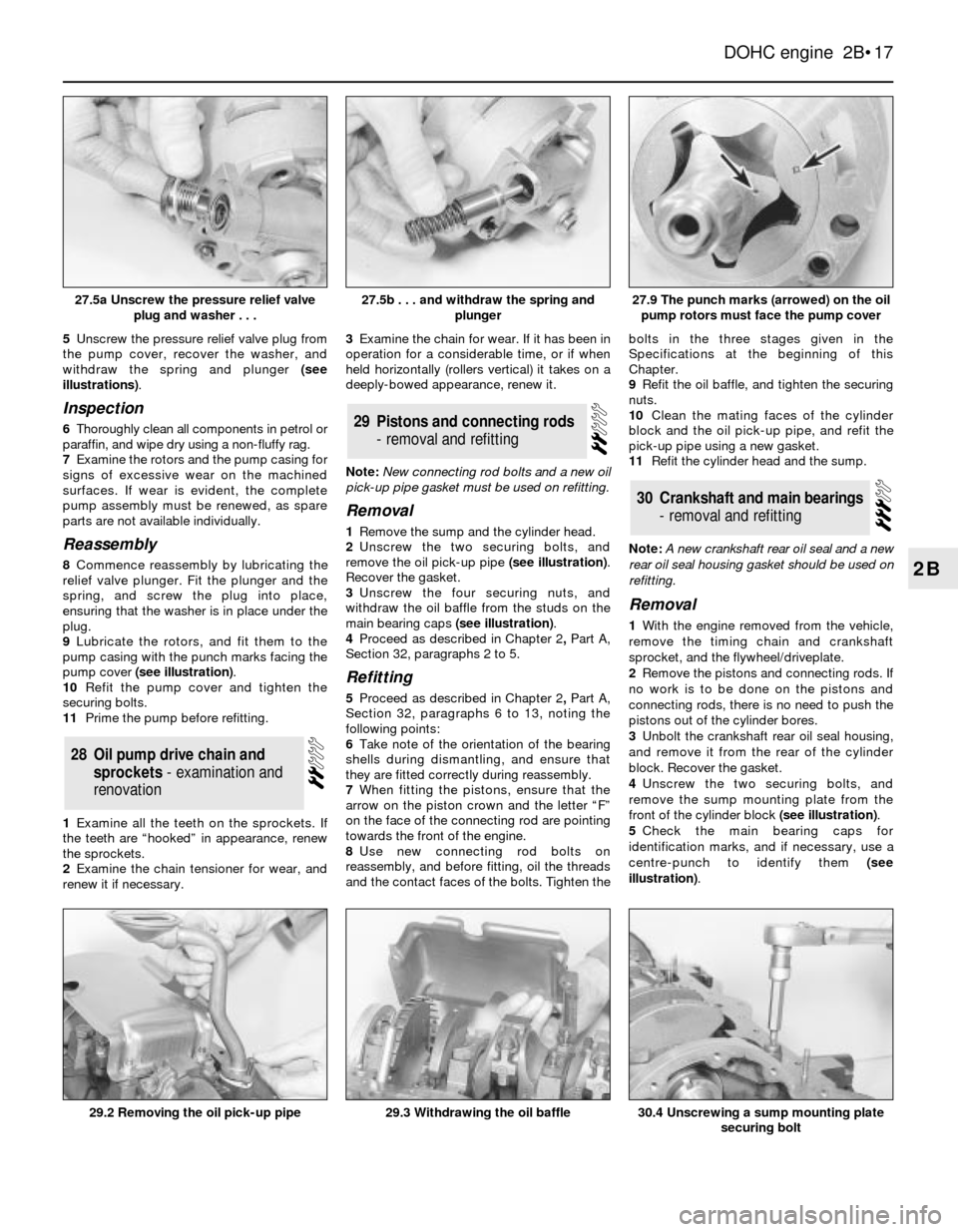
5Unscrew the pressure relief valve plug from
the pump cover, recover the washer, and
withdraw the spring and plunger (see
illustrations).
Inspection
6Thoroughly clean all components in petrol or
paraffin, and wipe dry using a non-fluffy rag.
7Examine the rotors and the pump casing for
signs of excessive wear on the machined
surfaces. If wear is evident, the complete
pump assembly must be renewed, as spare
parts are not available individually.
Reassembly
8Commence reassembly by lubricating the
relief valve plunger. Fit the plunger and the
spring, and screw the plug into place,
ensuring that the washer is in place under the
plug.
9Lubricate the rotors, and fit them to the
pump casing with the punch marks facing the
pump cover (see illustration).
10Refit the pump cover and tighten the
securing bolts.
11Prime the pump before refitting.
1Examine all the teeth on the sprockets. If
the teeth are “hooked” in appearance, renew
the sprockets.
2Examine the chain tensioner for wear, and
renew it if necessary.3Examine the chain for wear. If it has been in
operation for a considerable time, or if when
held horizontally (rollers vertical) it takes on a
deeply-bowed appearance, renew it.
Note: New connecting rod bolts and a new oil
pick-up pipe gasket must be used on refitting.
Removal
1Remove the sump and the cylinder head.
2Unscrew the two securing bolts, and
remove the oil pick-up pipe (see illustration).
Recover the gasket.
3Unscrew the four securing nuts, and
withdraw the oil baffle from the studs on the
main bearing caps (see illustration).
4Proceed as described in Chapter 2, PartA,
Section 32, paragraphs 2 to 5.
Refitting
5Proceed as described in Chapter 2, PartA,
Section 32, paragraphs 6 to 13, noting the
following points:
6Take note of the orientation of the bearing
shells during dismantling, and ensure that
they are fitted correctly during reassembly.
7When fitting the pistons, ensure that the
arrow on the piston crown and the letter “F”
on the face of the connecting rod are pointing
towards the front of the engine.
8Use new connecting rod bolts on
reassembly, and before fitting, oil the threads
and the contact faces of the bolts. Tighten thebolts in the three stages given in the
Specifications at the beginning of this
Chapter.
9Refit the oil baffle, and tighten the securing
nuts.
10Clean the mating faces of the cylinder
block and the oil pick-up pipe, and refit the
pick-up pipe using a new gasket.
11Refit the cylinder head and the sump.
Note: A new crankshaft rear oil seal and a new
rear oil seal housing gasket should be used on
refitting.
Removal
1With the engine removed from the vehicle,
remove the timing chain and crankshaft
sprocket, and the flywheel/driveplate.
2Remove the pistons and connecting rods. If
no work is to be done on the pistons and
connecting rods, there is no need to push the
pistons out of the cylinder bores.
3Unbolt the crankshaft rear oil seal housing,
and remove it from the rear of the cylinder
block. Recover the gasket.
4Unscrew the two securing bolts, and
remove the sump mounting plate from the
front of the cylinder block (see illustration).
5Check the main bearing caps for
identification marks, and if necessary, use a
centre-punch to identify them (see
illustration).
30Crankshaft and main bearings
- removal and refitting
29Pistons and connecting rods
- removal and refitting
28Oil pump drive chain and
sprockets - examination and
renovation
DOHC engine 2B•17
2B
27.5b . . . and withdraw the spring and
plunger
30.4 Unscrewing a sump mounting plate
securing bolt29.3 Withdrawing the oil baffle29.2 Removing the oil pick-up pipe
27.9 The punch marks (arrowed) on the oil
pump rotors must face the pump cover27.5a Unscrew the pressure relief valve
plug and washer . . .