torque FORD SIERRA 1985 1.G Fuel And Exhaust Systems Carburettor Workshop Manual
[x] Cancel search | Manufacturer: FORD, Model Year: 1985, Model line: SIERRA, Model: FORD SIERRA 1985 1.GPages: 20, PDF Size: 0.83 MB
Page 3 of 20
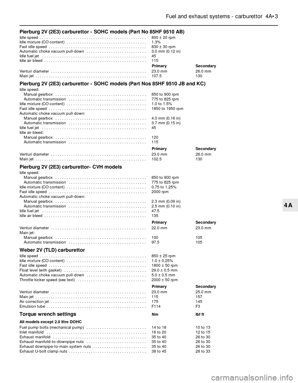
Pierburg 2V (2E3) carburettor - SOHC models (Part No 85HF 9510 AB)
Idle speed . . . . . . . . . . . . . . . . . . . . . . . . . . . . . . . . . . . . . . . . . . . . . . . .800 ±20 rpm
Idle mixture (CO content) . . . . . . . . . . . . . . . . . . . . . . . . . . . . . . . . . . . .1.3%
Fast idle speed . . . . . . . . . . . . . . . . . . . . . . . . . . . . . . . . . . . . . . . . . . . .830 ±30 rpm
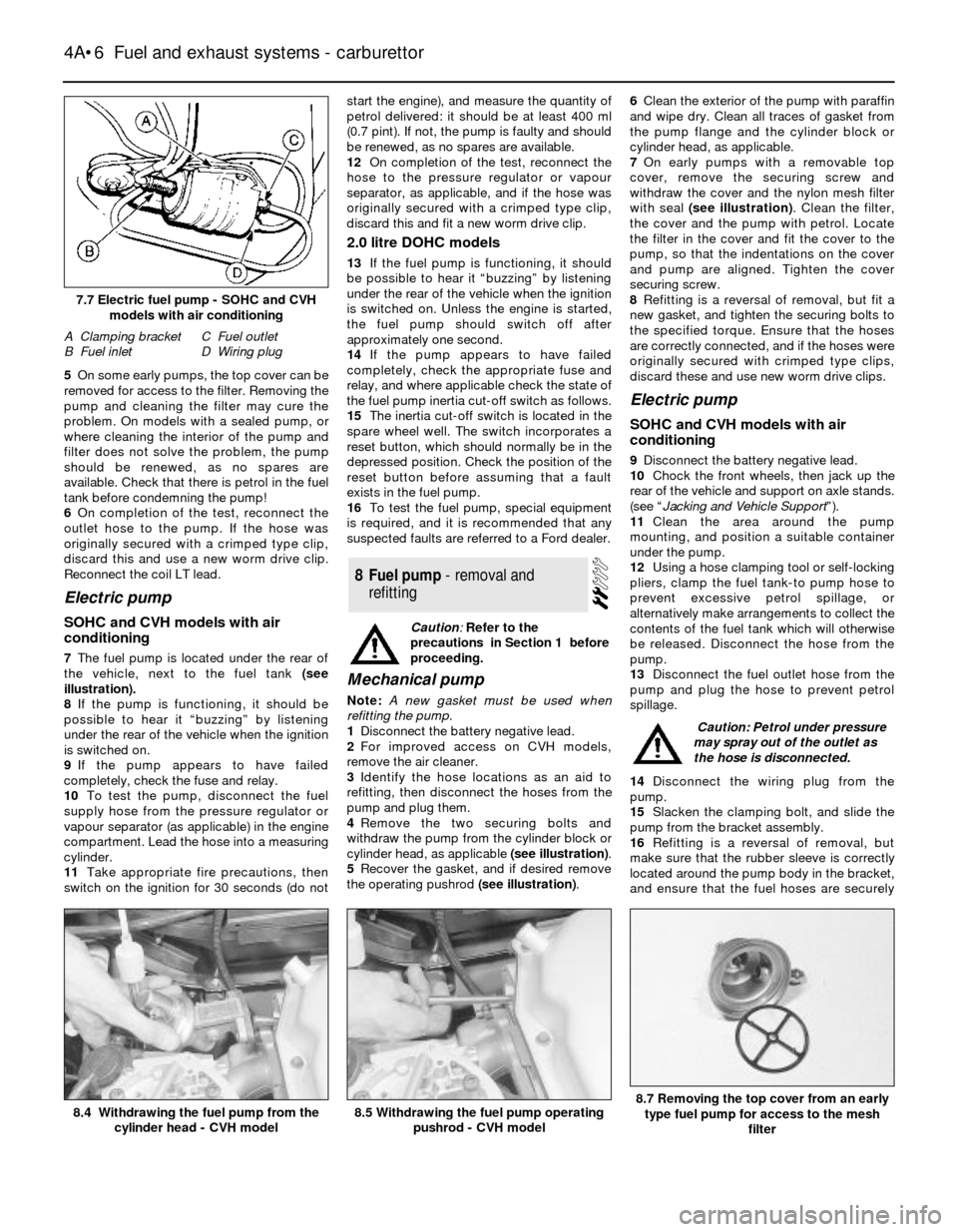
Automatic choke vacuum pull-down . . . . . . . . . . . . . . . . . . . . . . . . . . .3.0 mm (0.12 in)
Idle fuel jet . . . . . . . . . . . . . . . . . . . . . . . . . . . . . . . . . . . . . . . . . . . . . . .45
Idle air bleed . . . . . . . . . . . . . . . . . . . . . . . . . . . . . . . . . . . . . . . . . . . . . .115
PrimarySecondary
Venturi diameter . . . . . . . . . . . . . . . . . . . . . . . . . . . . . . . . . . . . . . . . . . .23.0 mm26.0 mm
Main jet . . . . . . . . . . . . . . . . . . . . . . . . . . . . . . . . . . . . . . . . . . . . . . . . . .107.5130
Pierburg 2V (2E3) carburettor - SOHC models (Part Nos 85HF 9510 JB and KC)
Idle speed:
Manual gearbox . . . . . . . . . . . . . . . . . . . . . . . . . . . . . . . . . . . . . . . . .850 to 900 rpm
Automatic transmission . . . . . . . . . . . . . . . . . . . . . . . . . . . . . . . . . . .775 to 825 rpm
Idle mixture (CO content) . . . . . . . . . . . . . . . . . . . . . . . . . . . . . . . . . . . .1.0 to 1.5%
Fast idle speed . . . . . . . . . . . . . . . . . . . . . . . . . . . . . . . . . . . . . . . . . . . .1850 to 1950 rpm
Automatic choke vacuum pull-down:
Manual gearbox . . . . . . . . . . . . . . . . . . . . . . . . . . . . . . . . . . . . . . . . .4.0 mm (0.16 in)
Automatic transmission . . . . . . . . . . . . . . . . . . . . . . . . . . . . . . . . . . .3.7 mm (0.15 in)
Idle fuel jet . . . . . . . . . . . . . . . . . . . . . . . . . . . . . . . . . . . . . . . . . . . . . . .45
Idle air bleed:
Manual gearbox . . . . . . . . . . . . . . . . . . . . . . . . . . . . . . . . . . . . . . . . .120
Automatic transmission . . . . . . . . . . . . . . . . . . . . . . . . . . . . . . . . . . .115
PrimarySecondary
Venturi diameter . . . . . . . . . . . . . . . . . . . . . . . . . . . . . . . . . . . . . . . . . . .23.0 mm26.0 mm
Main jet . . . . . . . . . . . . . . . . . . . . . . . . . . . . . . . . . . . . . . . . . . . . . . . . . .102.5130
Pierburg 2V (2E3) carburettor- CVH models
Idle speed:
Manual gearbox . . . . . . . . . . . . . . . . . . . . . . . . . . . . . . . . . . . . . . . . .850 to 900 rpm
Automatic transmission . . . . . . . . . . . . . . . . . . . . . . . . . . . . . . . . . . .775 to 825 rpm
Idle mixture (CO content) . . . . . . . . . . . . . . . . . . . . . . . . . . . . . . . . . . . .0.75 to 1.25%
Fast idle speed . . . . . . . . . . . . . . . . . . . . . . . . . . . . . . . . . . . . . . . . . . . .2000 rpm
Automatic choke vacuum pull-down:
Manual gearbox . . . . . . . . . . . . . . . . . . . . . . . . . . . . . . . . . . . . . . . . .2.3 mm (0.09 in)
Automatic transmission . . . . . . . . . . . . . . . . . . . . . . . . . . . . . . . . . . .2.5 mm (0.10 in)
Idle fuel jet . . . . . . . . . . . . . . . . . . . . . . . . . . . . . . . . . . . . . . . . . . . . . . .47.5
Idle air bleed . . . . . . . . . . . . . . . . . . . . . . . . . . . . . . . . . . . . . . . . . . . . . .135
PrimarySecondary
Venturi diameter . . . . . . . . . . . . . . . . . . . . . . . . . . . . . . . . . . . . . . . . . . .22.0 mm23.0 mm
Main jet:
Manual gearbox . . . . . . . . . . . . . . . . . . . . . . . . . . . . . . . . . . . . . . . . .100105
Automatic transmission . . . . . . . . . . . . . . . . . . . . . . . . . . . . . . . . . . .97.5105
Weber 2V (TLD) carburettor
Idle speed . . . . . . . . . . . . . . . . . . . . . . . . . . . . . . . . . . . . . . . . . . . . . . . .850 ±25 rpm
Idle mixture (CO content) . . . . . . . . . . . . . . . . . . . . . . . . . . . . . . . . . . . .1.0 ±0.25%
Fast idle speed . . . . . . . . . . . . . . . . . . . . . . . . . . . . . . . . . . . . . . . . . . . .1800 ±50 rpm
Float level (with gasket) . . . . . . . . . . . . . . . . . . . . . . . . . . . . . . . . . . . . .29.0 ±0.5 mm
Automatic choke vacuum pull-down . . . . . . . . . . . . . . . . . . . . . . . . . . .5.0 ±0.5 mm
Throttle kicker speed (see text) . . . . . . . . . . . . . . . . . . . . . . . . . . . . . . .2000 ±50 rpm
PrimarySecondary
Venturi diameter . . . . . . . . . . . . . . . . . . . . . . . . . . . . . . . . . . . . . . . . . . .23.0 mm25.0 mm
Main jet . . . . . . . . . . . . . . . . . . . . . . . . . . . . . . . . . . . . . . . . . . . . . . . . . .115157
Air correction jet . . . . . . . . . . . . . . . . . . . . . . . . . . . . . . . . . . . . . . . . . . .175145
Emulsion tube . . . . . . . . . . . . . . . . . . . . . . . . . . . . . . . . . . . . . . . . . . . . .F114F3
Torque wrench settingsNmlbf ft
All models except 2.0 litre DOHC
Fuel pump bolts (mechanical pump) . . . . . . . . . . . . . . . . . . . . . . . . . . .14 to 1810 to 13
Inlet manifold . . . . . . . . . . . . . . . . . . . . . . . . . . . . . . . . . . . . . . . . . . . . .16 to 2012 to 15
Exhaust manifold . . . . . . . . . . . . . . . . . . . . . . . . . . . . . . . . . . . . . . . . . .35 to 4026 to 30
Exhaust manifold-to-downpipe nuts . . . . . . . . . . . . . . . . . . . . . . . . . . .35 to 4026 to 30
Exhaust downpipe-to-main system nuts . . . . . . . . . . . . . . . . . . . . . . . .35 to 4026 to 30
Exhaust U-bolt clamp nuts . . . . . . . . . . . . . . . . . . . . . . . . . . . . . . . . . . .38 to 4528 to 33
Fuel and exhaust systems - carburettor 4A•3
4A
Page 6 of 20
5On some early pumps, the top cover can be
removed for access to the filter. Removing the
pump and cleaning the filter may cure the
problem. On models with a sealed pump, or
where cleaning the interior of the pump and
filter does not solve the problem, the pump
should be renewed, as no spares are
available. Check that there is petrol in the fuel
tank before condemning the pump!
6On completion of the test, reconnect the
outlet hose to the pump. If the hose was
originally secured with a crimped type clip,
discard this and use a new worm drive clip.
Reconnect the coil LT lead.
Electric pump
SOHC and CVH models with air
conditioning
7The fuel pump is located under the rear of
the vehicle, next to the fuel tank (see
illustration).
8If the pump is functioning, it should be
possible to hear it “buzzing” by listening
under the rear of the vehicle when the ignition
is switched on.
9If the pump appears to have failed
completely, check the fuse and relay.
10To test the pump, disconnect the fuel
supply hose from the pressure regulator or
vapour separator (as applicable) in the engine
compartment. Lead the hose into a measuring
cylinder.
11Take appropriate fire precautions, then
switch on the ignition for 30 seconds (do notstart the engine), and measure the quantity of
petrol delivered: it should be at least 400 ml
(0.7 pint). If not, the pump is faulty and should
be renewed, as no spares are available.
12On completion of the test, reconnect the
hose to the pressure regulator or vapour
separator, as applicable, and if the hose was
originally secured with a crimped type clip,
discard this and fit a new worm drive clip.
2.0 litre DOHC models
13If the fuel pump is functioning, it should
be possible to hear it “buzzing” by listening
under the rear of the vehicle when the ignition
is switched on. Unless the engine is started,
the fuel pump should switch off after
approximately one second.
14If the pump appears to have failed
completely, check the appropriate fuse and
relay, and where applicable check the state of
the fuel pump inertia cut-off switch as follows.
15The inertia cut-off switch is located in the
spare wheel well. The switch incorporates a
reset button, which should normally be in the
depressed position. Check the position of the
reset button before assuming that a fault
exists in the fuel pump.
16To test the fuel pump, special equipment
is required, and it is recommended that any
suspected faults are referred to a Ford dealer.
Mechanical pump
Note: A new gasket must be used when
refitting the pump.
1Disconnect the battery negative lead.
2For improved access on CVH models,
remove the air cleaner.
3Identify the hose locations as an aid to
refitting, then disconnect the hoses from the
pump and plug them.
4Remove the two securing bolts and
withdraw the pump from the cylinder block or
cylinder head, as applicable (see illustration).
5Recover the gasket, and if desired remove
the operating pushrod (see illustration).6Clean the exterior of the pump with paraffin
and wipe dry. Clean all traces of gasket from
the pump flange and the cylinder block or
cylinder head, as applicable.
7On early pumps with a removable top
cover, remove the securing screw and
withdraw the cover and the nylon mesh filter
with seal (see illustration). Clean the filter,
the cover and the pump with petrol. Locate
the filter in the cover and fit the cover to the
pump, so that the indentations on the cover
and pump are aligned. Tighten the cover
securing screw.
8Refitting is a reversal of removal, but fit a
new gasket, and tighten the securing bolts to
the specified torque. Ensure that the hoses
are correctly connected, and if the hoses were
originally secured with crimped type clips,
discard these and use new worm drive clips.
Electric pump
SOHC and CVH models with air
conditioning
9Disconnect the battery negative lead.
10Chock the front wheels, then jack up the
rear of the vehicle and support on axle stands.
(see “Jacking and Vehicle Support”).
11Clean the area around the pump
mounting, and position a suitable container
under the pump.
12Using a hose clamping tool or self-locking
pliers, clamp the fuel tank-to pump hose to
prevent excessive petrol spillage, or
alternatively make arrangements to collect the
contents of the fuel tank which will otherwise
be released. Disconnect the hose from the
pump.
13Disconnect the fuel outlet hose from the
pump and plug the hose to prevent petrol
spillage.
14Disconnect the wiring plug from the
pump.
15Slacken the clamping bolt, and slide the
pump from the bracket assembly.
16Refitting is a reversal of removal, but
make sure that the rubber sleeve is correctly
located around the pump body in the bracket,
and ensure that the fuel hoses are securely
8Fuel pump - removal and
refitting
4A•6Fuel and exhaust systems - carburettor
7.7 Electric fuel pump - SOHC and CVH
models with air conditioning
A Clamping bracket
B Fuel inletC Fuel outlet
D Wiring plug
8.5 Withdrawing the fuel pump operating
pushrod - CVH model8.4 Withdrawing the fuel pump from the
cylinder head - CVH model8.7 Removing the top cover from an early
type fuel pump for access to the mesh
filter
Caution: Refer to the
precautions in Section 1 before
proceeding.
Caution:Petrol under pressure
may spray out of the outlet as
the hose is disconnected.
Page 16 of 20
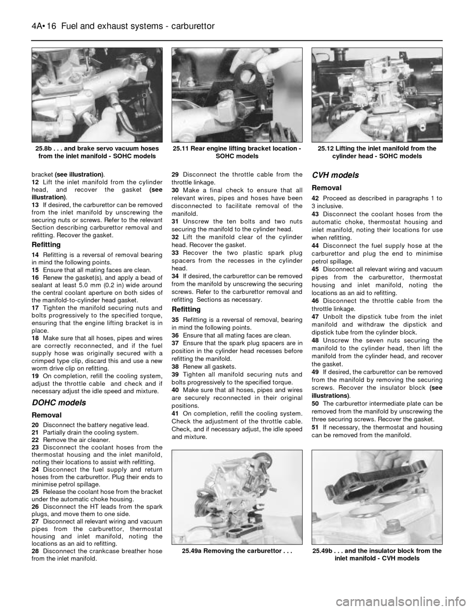
bracket (see illustration).
12Lift the inlet manifold from the cylinder
head, and recover the gasket (see
illustration).
13If desired, the carburettor can be removed
from the inlet manifold by unscrewing the
securing nuts or screws. Refer to the relevant
Section describing carburettor removal and
refitting. Recover the gasket.
Refitting
14Refitting is a reversal of removal bearing
in mind the following points.
15Ensure that all mating faces are clean.
16Renew the gasket(s), and apply a bead of
sealant at least 5.0 mm (0.2 in) wide around
the central coolant aperture on both sides of
the manifold-to-cylinder head gasket.
17Tighten the manifold securing nuts and
bolts progressively to the specified torque,
ensuring that the engine lifting bracket is in
place.
18Make sure that all hoses, pipes and wires
are correctly reconnected, and if the fuel
supply hose was originally secured with a
crimped type clip, discard this and use a new
worm drive clip on refitting.
19On completion, refill the cooling system,
adjust the throttle cable and check and if
necessary adjust the idle speed and mixture.
DOHC models
Removal
20Disconnect the battery negative lead.
21Partially drain the cooling system.
22Remove the air cleaner.
23Disconnect the coolant hoses from the
thermostat housing and the inlet manifold,
noting their locations to assist with refitting.
24Disconnect the fuel supply and return
hoses from the carburettor. Plug their ends to
minimise petrol spillage.
25Release the coolant hose from the bracket
under the automatic choke housing.
26Disconnect the HT leads from the spark
plugs, and move them to one side.
27Disconnect all relevant wiring and vacuum
pipes from the carburettor, thermostat
housing and inlet manifold, noting the
locations as an aid to refitting.
28Disconnect the crankcase breather hose
from the inlet manifold. 29Disconnect the throttle cable from the
throttle linkage.
30Make a final check to ensure that all
relevant wires, pipes and hoses have been
disconnected to facilitate removal of the
manifold.
31Unscrew the ten bolts and two nuts
securing the manifold to the cylinder head.
32Lift the manifold clear of the cylinder
head. Recover the gasket.
33Recover the two plastic spark plug
spacers from the recesses in the cylinder
head.
34If desired, the carburettor can be removed
from the manifold by unscrewing the securing
screws. Refer to the carburettor removal and
refitting Sections as necessary.
Refitting
35Refitting is a reversal of removal, bearing
in mind the following points.
36Ensure that all mating faces are clean.
37Ensure that the spark plug spacers are in
position in the cylinder head recesses before
refitting the manifold.
38Renew all gaskets.
39Tighten all manifold securing nuts and
bolts progressively to the specified torque.
40Make sure that all hoses, pipes and wires
are securely reconnected in their original
positions.
41On completion, refill the cooling system.
Check the adjustment of the throttle cable.
Check, and if necessary adjust, the idle speed
and mixture.
CVH models
Removal
42Proceed as described in paragraphs 1 to
3 inclusive.
43Disconnect the coolant hoses from the
automatic choke, thermostat housing and
inlet manifold, noting their locations for use
when refitting.
44Disconnect the fuel supply hose at the
carburettor and plug the end to minimise
petrol spillage.
45Disconnect all relevant wiring and vacuum
pipes from the carburettor, thermostat
housing and inlet manifold, noting the
locations as an aid to refitting.
46Disconnect the throttle cable from the
throttle linkage.
47Unbolt the dipstick tube from the inlet
manifold and withdraw the dipstick and
dipstick tube from the cylinder block.
48Unscrew the seven nuts securing the
manifold to the cylinder head, then lift the
manifold from the cylinder head, and recover
the gasket.
49If desired, the carburettor can be removed
from the manifold by removing the securing
screws. Recover the insulator block (see
illustrations).
50The carburettor intermediate plate can be
removed from the manifold by unscrewing the
three securing screws. Recover the gasket.
51If necessary, the thermostat and housing
can be removed from the manifold.
4A•16Fuel and exhaust systems - carburettor
25.8b . . . and brake servo vacuum hoses
from the inlet manifold - SOHC models25.12 Lifting the inlet manifold from the
cylinder head - SOHC models
25.49b . . . and the insulator block from the
inlet manifold - CVH models25.49a Removing the carburettor . . .
25.11 Rear engine lifting bracket location -
SOHC models
Page 17 of 20
Refitting
52Refitting is a reversal of removal, bearing
in mind the following points.
53Ensure that all mating faces are clean and
renew the gasket(s).
54Tighten the manifold securing nuts
progressively to the specified torque.
55Make sure that all hoses, pipes and wires
are correctly reconnected, and if the fuel
supply hose was originally secured with a
crimped type clip, discard this and use a new
worm drive clip on refitting.
56On completion, refill the cooling system,
adjust the throttle cable and check and if
necessary adjust the idle speed and mixture.
Removal
1Disconnect the battery negative lead.
2Remove the air cleaner and pull the hot air
pick-up pipe from the exhaust manifold hot air
shroud.
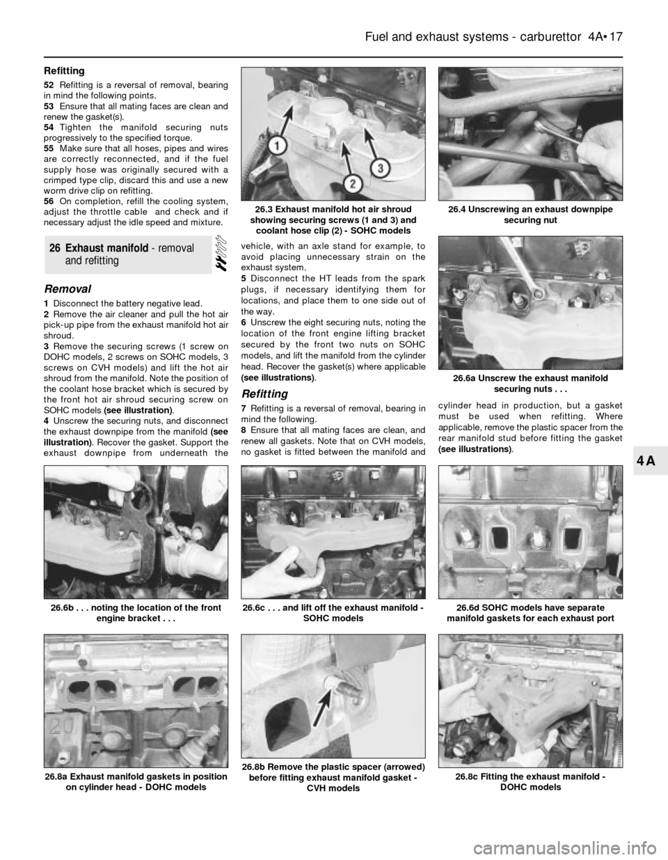
3Remove the securing screws (1 screw on
DOHC models, 2 screws on SOHC models, 3
screws on CVH models) and lift the hot air
shroud from the manifold. Note the position of
the coolant hose bracket which is secured by
the front hot air shroud securing screw on
SOHC models (see illustration).
4Unscrew the securing nuts, and disconnect
the exhaust downpipe from the manifold (see
illustration). Recover the gasket. Support the
exhaust downpipe from underneath thevehicle, with an axle stand for example, to
avoid placing unnecessary strain on the
exhaust system.
5Disconnect the HT leads from the spark
plugs, if necessary identifying them for
locations, and place them to one side out of
the way.
6Unscrew the eight securing nuts, noting the
location of the front engine lifting bracket
secured by the front two nuts on SOHC
models, and lift the manifold from the cylinder
head. Recover the gasket(s) where applicable
(see illustrations).
Refitting
7Refitting is a reversal of removal, bearing in
mind the following.
8Ensure that all mating faces are clean, and
renew all gaskets. Note that on CVH models,
no gasket is fitted between the manifold andcylinder head in production, but a gasket
must be used when refitting. Where
applicable, remove the plastic spacer from the
rear manifold stud before fitting the gasket
(see illustrations).
26Exhaust manifold - removal
and refitting
Fuel and exhaust systems - carburettor 4A•17
4A
26.6a Unscrew the exhaust manifold
securing nuts . . .
26.8c Fitting the exhaust manifold -
DOHC models26.8b Remove the plastic spacer (arrowed)
before fitting exhaust manifold gasket -
CVH models26.8a Exhaust manifold gaskets in position
on cylinder head - DOHC models
26.6d SOHC models have separate
manifold gaskets for each exhaust port26.6c . . . and lift off the exhaust manifold -
SOHC models26.6b . . . noting the location of the front
engine bracket . . .
26.4 Unscrewing an exhaust downpipe
securing nut26.3 Exhaust manifold hot air shroud
showing securing screws (1 and 3) and
coolant hose clip (2) - SOHC models
Page 18 of 20
9Tighten the manifold securing nuts
progressively to the specified torque, and
similarly tighten the exhaust downpipe
securing nuts. Do not forget to fit the engine
lifting bracket on SOHC models.
10Ensure that the HT leads are reconnected
to their correct cylinders.
Inspection
1The exhaust system should be examined for
leaks, damage, and security at regular
intervals. To do this, apply the handbrake, then
start the engine and allow it to idle. Lie down on
each side of the vehicle in turn and check the
full length of the exhaust system for leaks,
while an assistant temporarily places a wad of
cloth over the tailpipe. If a leak is evident, stop
the engine and use a proprietary repair kit to
seal it. If an excessive leak or damage is
evident, renew the relevant section of the
exhaust system. Check the rubber mountings
for deterioration and renew if necessary.
Removal
2To remove the exhaust system, jack up the
front and rear of the vehicle and support on
axle stands (see “Jacking and Vehicle
Support”).
3If desired, the exhaust downpipe can be
removed independently of the remainder of
the system, and similarly the main part of the
system can be removed, leaving the
downpipe in place.
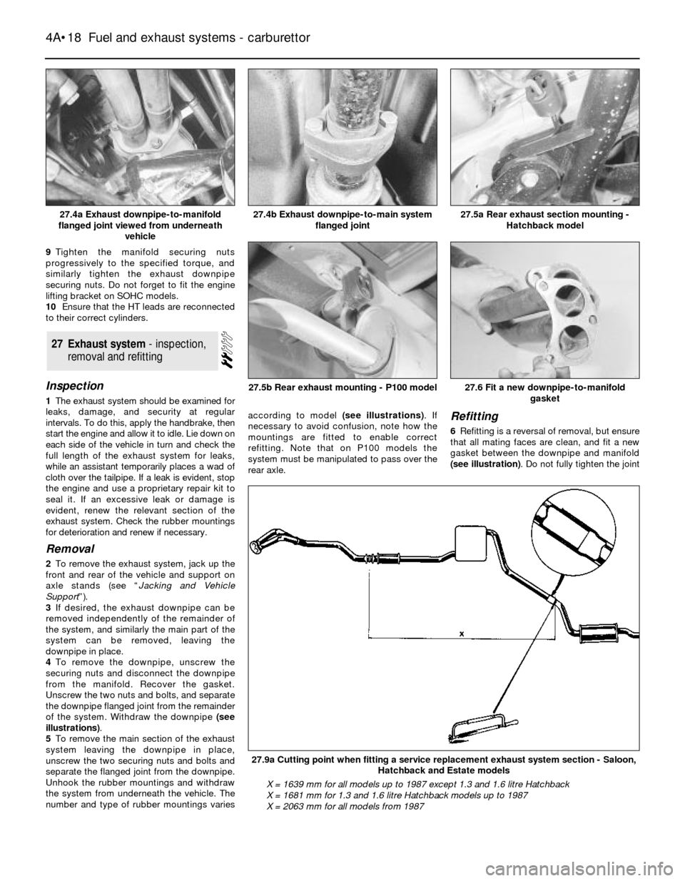
4To remove the downpipe, unscrew the
securing nuts and disconnect the downpipe
from the manifold. Recover the gasket.
Unscrew the two nuts and bolts, and separate
the downpipe flanged joint from the remainder
of the system. Withdraw the downpipe (see
illustrations).
5To remove the main section of the exhaust
system leaving the downpipe in place,
unscrew the two securing nuts and bolts and
separate the flanged joint from the downpipe.
Unhook the rubber mountings and withdraw
the system from underneath the vehicle. The
number and type of rubber mountings variesaccording to model (see illustrations). If
necessary to avoid confusion, note how the
mountings are fitted to enable correct
refitting. Note that on P100 models the
system must be manipulated to pass over the
rear axle.
Refitting
6Refitting is a reversal of removal, but ensure
that all mating faces are clean, and fit a new
gasket between the downpipe and manifold
(see illustration). Do not fully tighten the joint
27Exhaust system - inspection,
removal and refitting
4A•18Fuel and exhaust systems - carburettor
27.4a Exhaust downpipe-to-manifold
flanged joint viewed from underneath
vehicle27.5a Rear exhaust section mounting -
Hatchback model
27.9a Cutting point when fitting a service replacement exhaust system section - Saloon,
Hatchback and Estate models
X = 1639 mm for all models up to 1987 except 1.3 and 1.6 litre Hatchback
X = 1681 mm for 1.3 and 1.6 litre Hatchback models up to 1987
X = 2063 mm for all models from 1987
27.6 Fit a new downpipe-to-manifold
gasket27.5b Rear exhaust mounting - P100 model
27.4b Exhaust downpipe-to-main system
flanged joint