coolant level FORD SIERRA 1985 1.G Routine Manintenance And Servicing Workshop Manual
[x] Cancel search | Manufacturer: FORD, Model Year: 1985, Model line: SIERRA, Model: FORD SIERRA 1985 1.GPages: 22, PDF Size: 1.26 MB
Page 1 of 22
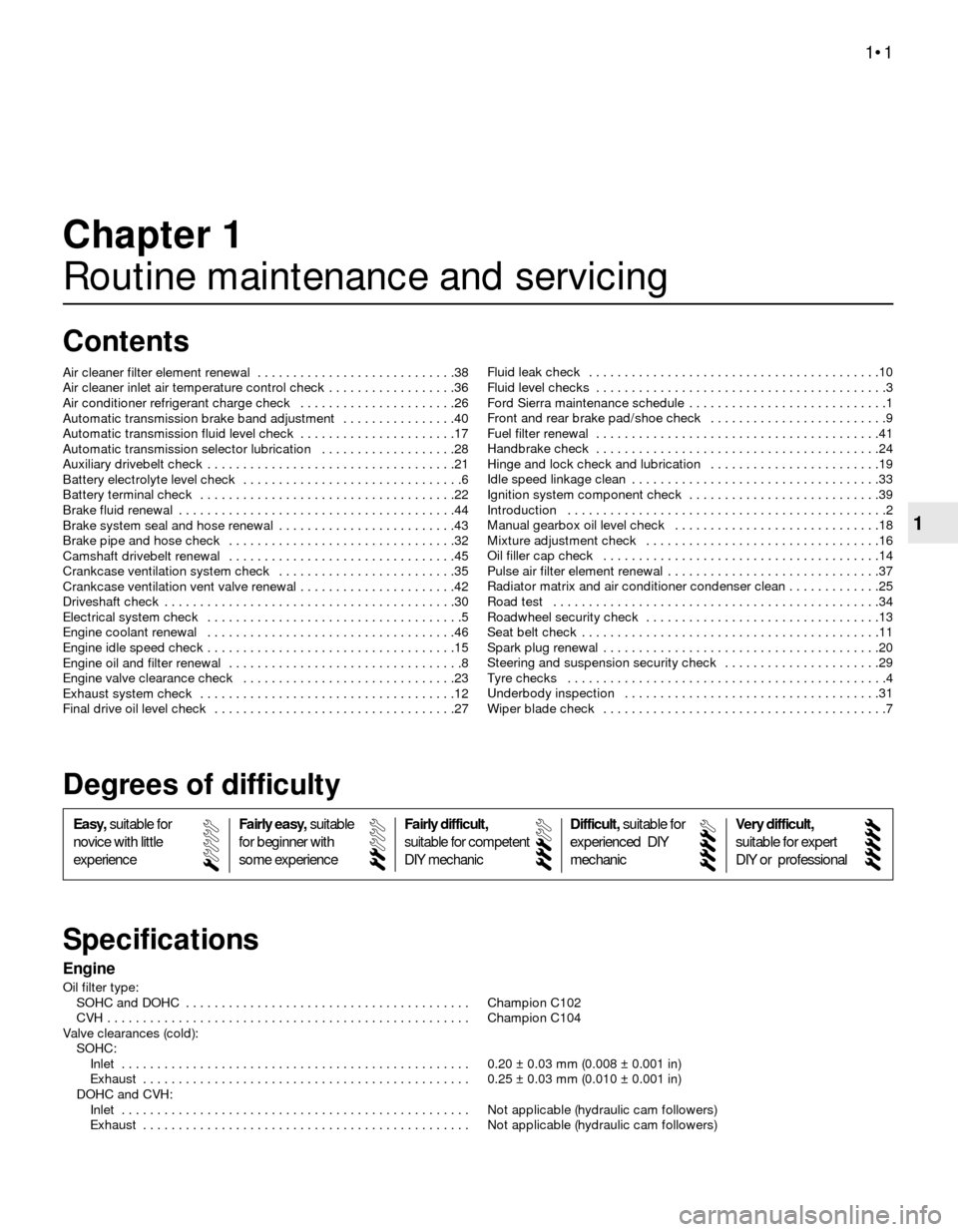
Engine
Oil filter type:
SOHC and DOHC . . . . . . . . . . . . . . . . . . . . . . . . . . . . . . . . . . . . . . . . Champion C102
CVH . . . . . . . . . . . . . . . . . . . . . . . . . . . . . . . . . . . . . . . . . . . . . . . . . . . Champion C104
Valve clearances (cold):
SOHC:
Inlet . . . . . . . . . . . . . . . . . . . . . . . . . . . . . . . . . . . . . . . . . . . . . . . . . 0.20 ± 0.03 mm (0.008 ± 0.001 in)
Exhaust . . . . . . . . . . . . . . . . . . . . . . . . . . . . . . . . . . . . . . . . . . . . . . 0.25 ± 0.03 mm (0.010 ± 0.001 in)
DOHC and CVH:
Inlet . . . . . . . . . . . . . . . . . . . . . . . . . . . . . . . . . . . . . . . . . . . . . . . . . Not applicable (hydraulic cam followers)
Exhaust . . . . . . . . . . . . . . . . . . . . . . . . . . . . . . . . . . . . . . . . . . . . . . Not applicable (hydraulic cam followers)
Chapter 1
Routine maintenance and servicing
Air cleaner filter element renewal . . . . . . . . . . . . . . . . . . . . . . . . . . . .38
Air cleaner inlet air temperature control check . . . . . . . . . . . . . . . . . .36
Air conditioner refrigerant charge check . . . . . . . . . . . . . . . . . . . . . .26
Automatic transmission brake band adjustment . . . . . . . . . . . . . . . .40
Automatic transmission fluid level check . . . . . . . . . . . . . . . . . . . . . .17
Automatic transmission selector lubrication . . . . . . . . . . . . . . . . . . .28
Auxiliary drivebelt check . . . . . . . . . . . . . . . . . . . . . . . . . . . . . . . . . . .21
Battery electrolyte level check . . . . . . . . . . . . . . . . . . . . . . . . . . . . . . .6
Battery terminal check . . . . . . . . . . . . . . . . . . . . . . . . . . . . . . . . . . . .22
Brake fluid renewal . . . . . . . . . . . . . . . . . . . . . . . . . . . . . . . . . . . . . . .44
Brake system seal and hose renewal . . . . . . . . . . . . . . . . . . . . . . . . .43
Brake pipe and hose check . . . . . . . . . . . . . . . . . . . . . . . . . . . . . . . .32
Camshaft drivebelt renewal . . . . . . . . . . . . . . . . . . . . . . . . . . . . . . . .45
Crankcase ventilation system check . . . . . . . . . . . . . . . . . . . . . . . . .35
Crankcase ventilation vent valve renewal . . . . . . . . . . . . . . . . . . . . . .42
Driveshaft check . . . . . . . . . . . . . . . . . . . . . . . . . . . . . . . . . . . . . . . . .30
Electrical system check . . . . . . . . . . . . . . . . . . . . . . . . . . . . . . . . . . . .5
Engine coolant renewal . . . . . . . . . . . . . . . . . . . . . . . . . . . . . . . . . . .46
Engine idle speed check . . . . . . . . . . . . . . . . . . . . . . . . . . . . . . . . . . .15
Engine oil and filter renewal . . . . . . . . . . . . . . . . . . . . . . . . . . . . . . . . .8
Engine valve clearance check . . . . . . . . . . . . . . . . . . . . . . . . . . . . . .23
Exhaust system check . . . . . . . . . . . . . . . . . . . . . . . . . . . . . . . . . . . .12
Final drive oil level check . . . . . . . . . . . . . . . . . . . . . . . . . . . . . . . . . .27Fluid leak check . . . . . . . . . . . . . . . . . . . . . . . . . . . . . . . . . . . . . . . . .10
Fluid level checks . . . . . . . . . . . . . . . . . . . . . . . . . . . . . . . . . . . . . . . . .3
Ford Sierra maintenance schedule . . . . . . . . . . . . . . . . . . . . . . . . . . . .1
Front and rear brake pad/shoe check . . . . . . . . . . . . . . . . . . . . . . . . .9
Fuel filter renewal . . . . . . . . . . . . . . . . . . . . . . . . . . . . . . . . . . . . . . . .41
Handbrake check . . . . . . . . . . . . . . . . . . . . . . . . . . . . . . . . . . . . . . . .24
Hinge and lock check and lubrication . . . . . . . . . . . . . . . . . . . . . . . .19
Idle speed linkage clean . . . . . . . . . . . . . . . . . . . . . . . . . . . . . . . . . . .33
Ignition system component check . . . . . . . . . . . . . . . . . . . . . . . . . . .39
Introduction . . . . . . . . . . . . . . . . . . . . . . . . . . . . . . . . . . . . . . . . . . . . .2
Manual gearbox oil level check . . . . . . . . . . . . . . . . . . . . . . . . . . . . .18
Mixture adjustment check . . . . . . . . . . . . . . . . . . . . . . . . . . . . . . . . .16
Oil filler cap check . . . . . . . . . . . . . . . . . . . . . . . . . . . . . . . . . . . . . . .14
Pulse air filter element renewal . . . . . . . . . . . . . . . . . . . . . . . . . . . . . .37
Radiator matrix and air conditioner condenser clean . . . . . . . . . . . . .25
Road test . . . . . . . . . . . . . . . . . . . . . . . . . . . . . . . . . . . . . . . . . . . . . .34
Roadwheel security check . . . . . . . . . . . . . . . . . . . . . . . . . . . . . . . . .13
Seat belt check . . . . . . . . . . . . . . . . . . . . . . . . . . . . . . . . . . . . . . . . . .11
Spark plug renewal . . . . . . . . . . . . . . . . . . . . . . . . . . . . . . . . . . . . . . .20
Steering and suspension security check . . . . . . . . . . . . . . . . . . . . . .29
Tyre checks . . . . . . . . . . . . . . . . . . . . . . . . . . . . . . . . . . . . . . . . . . . . .4
Underbody inspection . . . . . . . . . . . . . . . . . . . . . . . . . . . . . . . . . . . .31
Wiper blade check . . . . . . . . . . . . . . . . . . . . . . . . . . . . . . . . . . . . . . . .7
1•1
Easy,suitable for
novice with little
experienceFairly easy,suitable
for beginner with
some experienceFairly difficult,
suitable for competent
DIY mechanic
Difficult,suitable for
experienced DIY
mechanicVery difficult,
suitable for expert
DIY or professional
Degrees of difficulty
Specifications Contents
1
Page 2 of 22

Cooling system
Drivebelt tensions:
Air conditioning system compressor . . . . . . . . . . . . . . . . . . . . . . . . .10.0 mm (0.4 in) deflection at the midpoint of the belt’s longest run
under firm thumb pressure
Coolant pump/alternator . . . . . . . . . . . . . . . . . . . . . . . . . . . . . . . . . .10.0 mm (0.4 in) deflection midway between coolant pump and
alternator (or power steering pump) pulleys under firm thumb pressure
Fuel system
Air filter element:
Carburettor type:
1.3 and 1.6 litre (SOHC - Ford carburettor) . . . . . . . . . . . . . . . . . .Champion W110
1.6 litre (SOHC - Weber carburettor) and 1.8 litre SOHC . . . . . . . .Champion W118
1.6 litre (SOHC - 1984-on) and 2.0 litre SOHC . . . . . . . . . . . . . . . .Champion W152
1.8 litre CVH . . . . . . . . . . . . . . . . . . . . . . . . . . . . . . . . . . . . . . . . . .Champion W219
2.0 litre DOHC . . . . . . . . . . . . . . . . . . . . . . . . . . . . . . . . . . . . . . . . .Champion W152
Fuel injection type:
2.0 litre SOHC and DOHC . . . . . . . . . . . . . . . . . . . . . . . . . . . . . . . .Champion U507
1.6 and 1.8 litre (R6A type) CVH . . . . . . . . . . . . . . . . . . . . . . . . . . .Champion W219
Fuel filter:
All fuel injection models . . . . . . . . . . . . . . . . . . . . . . . . . . . . . . . . . . .Champion L204
Ignition system
Spark plugs:
Make and type:
All except 1.8 CVH, CVH (R6A), 2.0 DOHC and P100 . . . . . . . . . . . .Champion RF7YCC or RF7YC
1.8 litre CVH . . . . . . . . . . . . . . . . . . . . . . . . . . . . . . . . . . . . . . . . . . . .Champion RC7YCC or RC7YC
P100 . . . . . . . . . . . . . . . . . . . . . . . . . . . . . . . . . . . . . . . . . . . . . . . . . .Champion RF7YC or F7YC
1.6 and 1.8 litre (R6A type) CVH . . . . . . . . . . . . . . . . . . . . . . . . . . . . .Champion RC7YCC
2.0 litre DOHC . . . . . . . . . . . . . . . . . . . . . . . . . . . . . . . . . . . . . . . . . . .Champion RC7YCC
Electrode gap*:
Champion F7YCC or RC7YCC . . . . . . . . . . . . . . . . . . . . . . . . . . . . . .0.8 mm (0.032 in)
Champion RF7YC, F7YC or RC7YC . . . . . . . . . . . . . . . . . . . . . . . . . .0.7 mm (0.028 in)
Ignition HT leads
Resistance . . . . . . . . . . . . . . . . . . . . . . . . . . . . . . . . . . . . . . . . . . . . . . .30 k ohms maximum per lead
Type:
All SOHC models . . . . . . . . . . . . . . . . . . . . . . . . . . . . . . . . . . . . . . . .Champion LS-09 or LS-10 boxed set
1.8 litre CVH . . . . . . . . . . . . . . . . . . . . . . . . . . . . . . . . . . . . . . . . . . . .Champion LS-10 boxed set
1.6 and 1.8 litre (R6A type) CVH . . . . . . . . . . . . . . . . . . . . . . . . . . . .Champion LS-30 boxed set
2.0 litre DOHC . . . . . . . . . . . . . . . . . . . . . . . . . . . . . . . . . . . . . . . . . . .Champion LS-29 boxed set
*The spark plug gap quoted is that recommended by Champion for their specified plugs listed above. If spark plugs of any other type are to be
fitted, refer to their manufacturer’s recommendations.
Brakes
Brake pad friction material minimum thickness . . . . . . . . . . . . . . . . . . .1.5 mm (0.06 in)
Brake shoe friction material minimum thickness . . . . . . . . . . . . . . . . . .1.0 mm (0.04 in)
Torque wrench settingsNmlbf ft
Engine oil drain plug:
SOHC and DOHC . . . . . . . . . . . . . . . . . . . . . . . . . . . . . . . . . . . . . . . .21 to 2816 to 21
CVH . . . . . . . . . . . . . . . . . . . . . . . . . . . . . . . . . . . . . . . . . . . . . . . . . . .20 to 3015 to 22
Engine block coolant drain plug (where fitted) . . . . . . . . . . . . . . . . . . . .21 to 25 16 to 18
Manual gearbox:
Oil filler/level plug:
A,B,C and N types . . . . . . . . . . . . . . . . . . . . . . . . . . . . . . . . . . . . .33 to 4124 to 30
MT75 type . . . . . . . . . . . . . . . . . . . . . . . . . . . . . . . . . . . . . . . . . . . .29 to 4121 to 30
Oil drain plug:
MT75 type . . . . . . . . . . . . . . . . . . . . . . . . . . . . . . . . . . . . . . . . . . . .29 to 4121 to 30
Final drive oil filler plug . . . . . . . . . . . . . . . . . . . . . . . . . . . . . . . . . . . . . .35 to 4526 to 33
Roadwheel nuts:
Saloon, Hatchback and Estate models (steel and alloy wheels) . . . .70 to 10052 to 74
P100 models . . . . . . . . . . . . . . . . . . . . . . . . . . . . . . . . . . . . . . . . . . . .85 to 9063 to 66
Spark plugs:
SOHC models . . . . . . . . . . . . . . . . . . . . . . . . . . . . . . . . . . . . . . . . . . .20 to 2815 to 21
CVH models . . . . . . . . . . . . . . . . . . . . . . . . . . . . . . . . . . . . . . . . . . . .18 to 3313 to 24
DOHC models . . . . . . . . . . . . . . . . . . . . . . . . . . . . . . . . . . . . . . . . . . .15 to 2111 to 15
Brake caliper guide bolts:
Front . . . . . . . . . . . . . . . . . . . . . . . . . . . . . . . . . . . . . . . . . . . . . . . . . .20 to 2515 to 18
Rear . . . . . . . . . . . . . . . . . . . . . . . . . . . . . . . . . . . . . . . . . . . . . . . . . . .31 to 3523 to 26
1•2Servicing specifications
Page 4 of 22
1•4Maintenance schedule
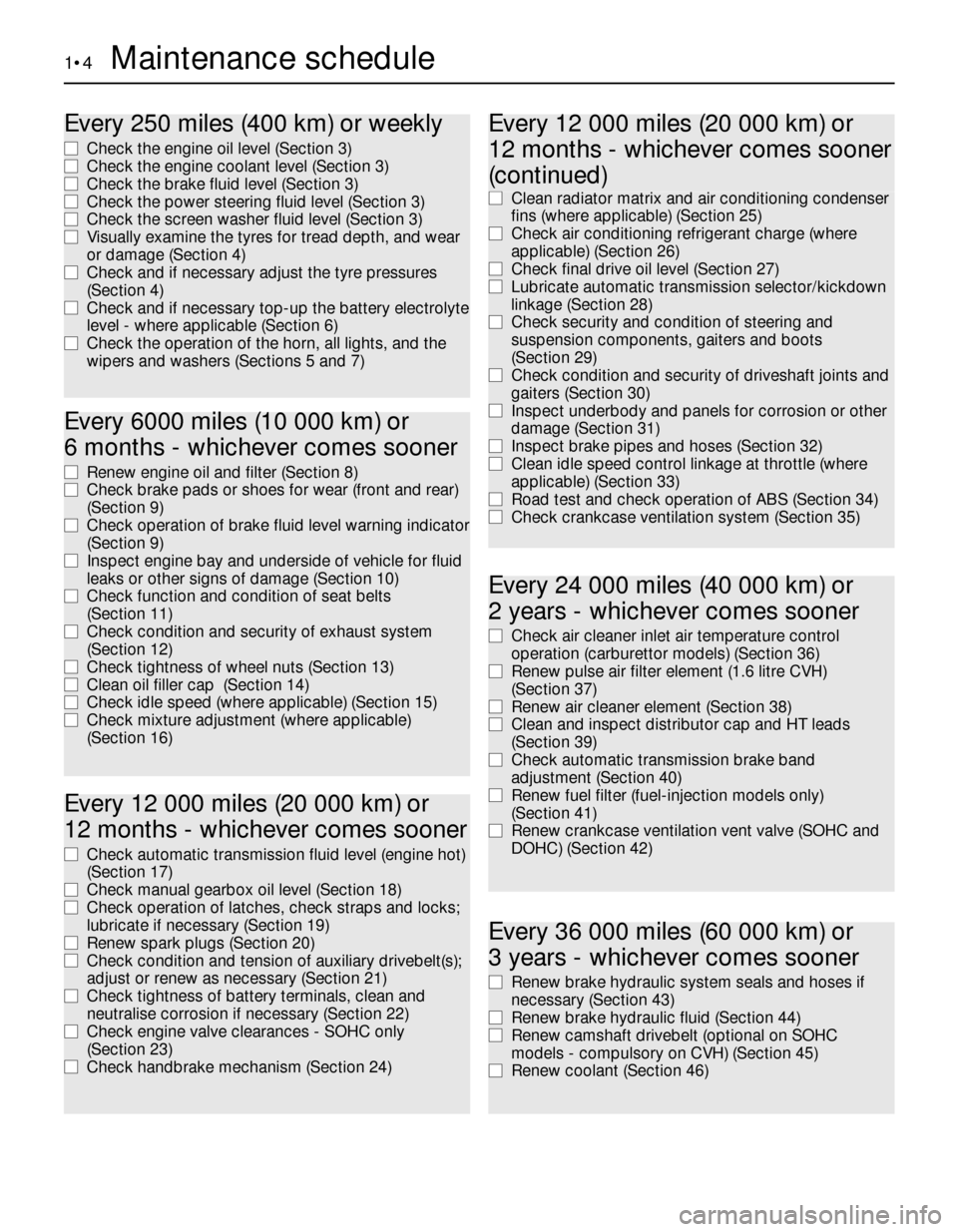
Every 250 miles (400 km) or weekly
m mCheck the engine oil level (Section 3)
m mCheck the engine coolant level (Section 3)
m mCheck the brake fluid level (Section 3)
m mCheck the power steering fluid level (Section 3)
m mCheck the screen washer fluid level (Section 3)
m mVisually examine the tyres for tread depth, and wear
or damage (Section 4)
m mCheck and if necessary adjust the tyre pressures
(Section 4)
m mCheck and if necessary top-up the battery electrolyte
level - where applicable (Section 6)
m mCheck the operation of the horn, all lights, and the
wipers and washers (Sections 5 and 7)
Every 6000 miles (10 000 km) or
6 months - whichever comes sooner
m mRenew engine oil and filter (Section 8)
m mCheck brake pads or shoes for wear (front and rear)
(Section 9)
m mCheck operation of brake fluid level warning indicator
(Section 9)
m mInspect engine bay and underside of vehicle for fluid
leaks or other signs of damage (Section 10)
m mCheck function and condition of seat belts
(Section 11)
m mCheck condition and security of exhaust system
(Section 12)
m mCheck tightness of wheel nuts (Section 13)
m mClean oil filler cap (Section 14)
m mCheck idle speed (where applicable) (Section 15)
m mCheck mixture adjustment (where applicable)
(Section 16)
Every 12 000 miles (20 000 km) or
12 months - whichever comes sooner
m mCheck automatic transmission fluid level (engine hot)
(Section 17)
m mCheck manual gearbox oil level (Section 18)
m mCheck operation of latches, check straps and locks;
lubricate if necessary (Section 19)
m mRenew spark plugs (Section 20)
m mCheck condition and tension of auxiliary drivebelt(s);
adjust or renew as necessary (Section 21)
m mCheck tightness of battery terminals, clean and
neutralise corrosion if necessary (Section 22)
m mCheck engine valve clearances - SOHC only
(Section 23)
m mCheck handbrake mechanism (Section 24)
Every 24 000 miles (40 000 km) or
2 years - whichever comes sooner
m mCheck air cleaner inlet air temperature control
operation (carburettor models) (Section 36)
m mRenew pulse air filter element (1.6 litre CVH)
(Section 37)
m mRenew air cleaner element (Section 38)
m mClean and inspect distributor cap and HT leads
(Section 39)
m mCheck automatic transmission brake band
adjustment (Section 40)
m mRenew fuel filter (fuel-injection models only)
(Section 41)
m mRenew crankcase ventilation vent valve (SOHC and
DOHC) (Section 42)
m mClean radiator matrix and air conditioning condenser
fins (where applicable) (Section 25)
m mCheck air conditioning refrigerant charge (where
applicable) (Section 26)
m mCheck final drive oil level (Section 27)
m mLubricate automatic transmission selector/kickdown
linkage (Section 28)
m mCheck security and condition of steering and
suspension components, gaiters and boots
(Section 29)
m mCheck condition and security of driveshaft joints and
gaiters (Section 30)
m mInspect underbody and panels for corrosion or other
damage (Section 31)
m mInspect brake pipes and hoses (Section 32)
m mClean idle speed control linkage at throttle (where
applicable) (Section 33)
m mRoad test and check operation of ABS (Section 34)
m mCheck crankcase ventilation system (Section 35)
Every 36 000 miles (60 000 km) or
3 years - whichever comes sooner
m mRenew brake hydraulic system seals and hoses if
necessary (Section 43)
m mRenew brake hydraulic fluid (Section 44)
m mRenew camshaft drivebelt (optional on SOHC
models - compulsory on CVH) (Section 45)
m mRenew coolant (Section 46)
Every 12 000 miles (20 000 km) or
12 months - whichever comes sooner
(continued)
Page 5 of 22
Maintenance - component location 1•5
1
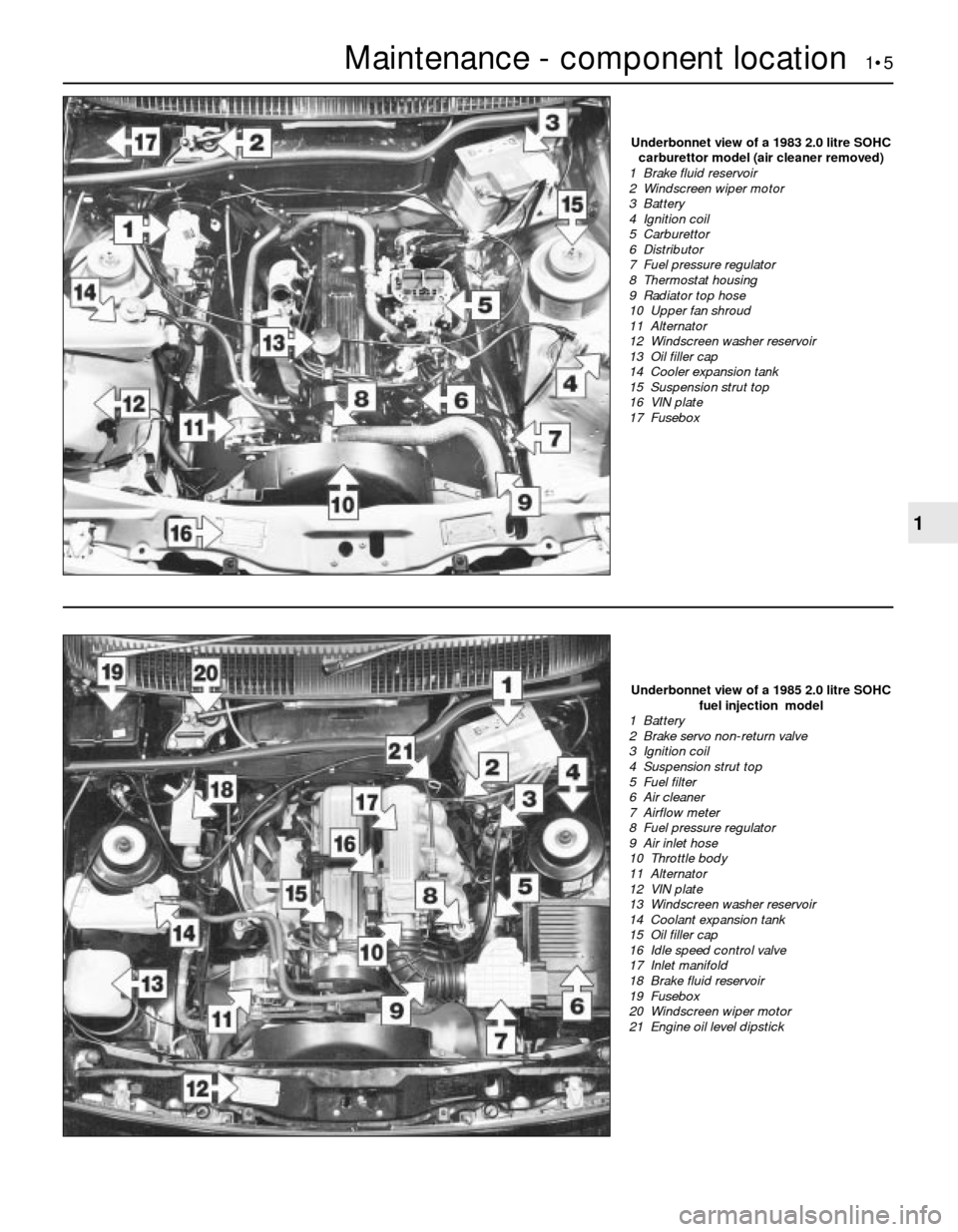
Underbonnet view of a 1985 2.0 litre SOHC
fuel injection model
1 Battery
2 Brake servo non-return valve
3 Ignition coil
4 Suspension strut top
5 Fuel filter
6 Air cleaner
7 Airflow meter
8 Fuel pressure regulator
9 Air inlet hose
10 Throttle body
11 Alternator
12 VIN plate
13 Windscreen washer reservoir
14 Coolant expansion tank
15 Oil filler cap
16 Idle speed control valve
17 Inlet manifold
18 Brake fluid reservoir
19 Fusebox
20 Windscreen wiper motor
21 Engine oil level dipstick
Underbonnet view of a 1983 2.0 litre SOHC
carburettor model (air cleaner removed)
1 Brake fluid reservoir
2 Windscreen wiper motor
3 Battery
4 Ignition coil
5 Carburettor
6 Distributor
7 Fuel pressure regulator
8 Thermostat housing
9 Radiator top hose
10 Upper fan shroud
11 Alternator
12 Windscreen washer reservoir
13 Oil filler cap
14 Cooler expansion tank
15 Suspension strut top
16 VIN plate
17 Fusebox
Page 6 of 22
1•6Maintenance - component location
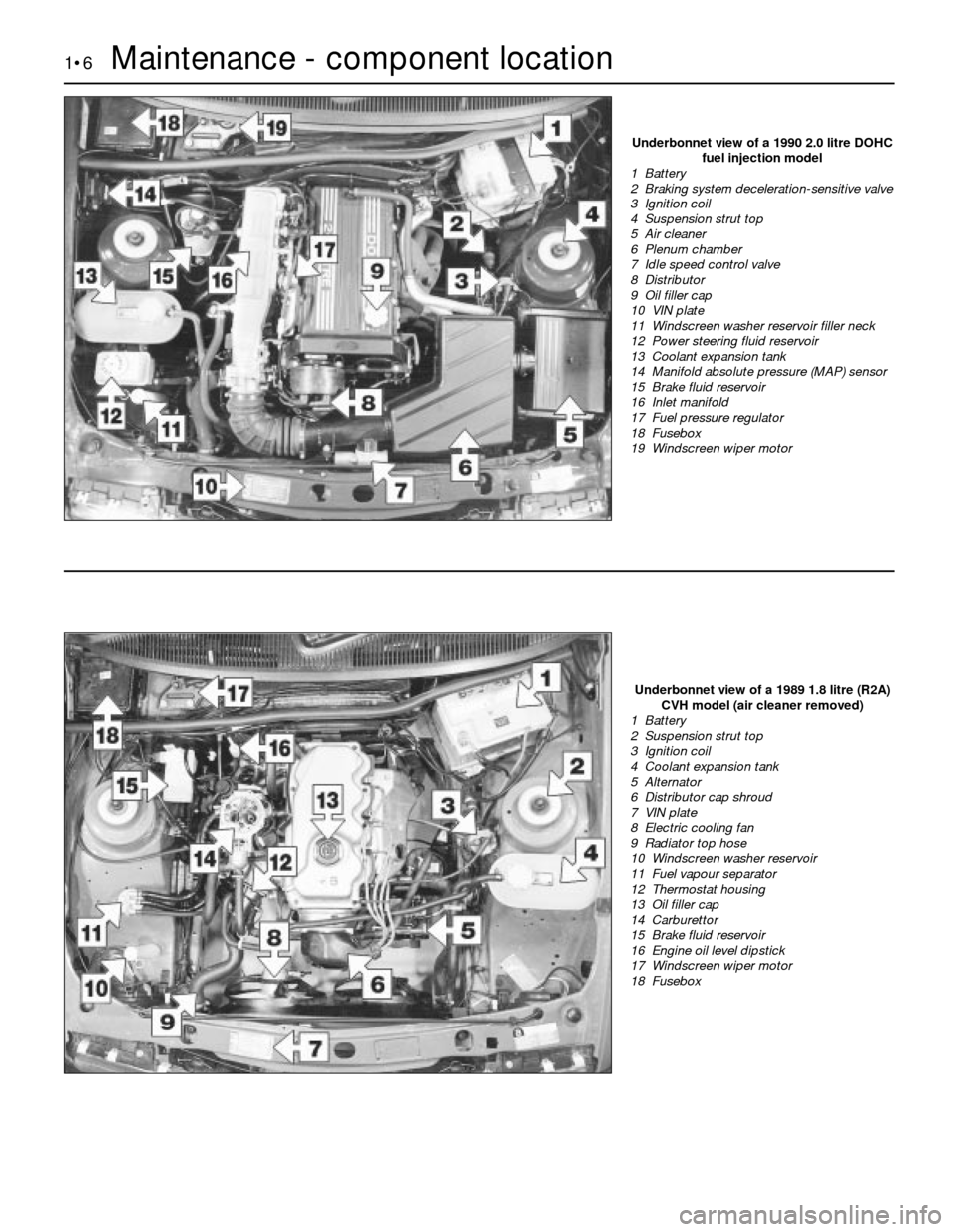
Underbonnet view of a 1990 2.0 litre DOHC
fuel injection model
1 Battery
2 Braking system deceleration-sensitive valve
3 Ignition coil
4 Suspension strut top
5 Air cleaner
6 Plenum chamber
7 Idle speed control valve
8 Distributor
9 Oil filler cap
10 VIN plate
11 Windscreen washer reservoir filler neck
12 Power steering fluid reservoir
13 Coolant expansion tank
14 Manifold absolute pressure (MAP) sensor
15 Brake fluid reservoir
16 Inlet manifold
17 Fuel pressure regulator
18 Fusebox
19 Windscreen wiper motor
Underbonnet view of a 1989 1.8 litre (R2A)
CVH model (air cleaner removed)
1 Battery
2 Suspension strut top
3 Ignition coil
4 Coolant expansion tank
5 Alternator
6 Distributor cap shroud
7 VIN plate
8 Electric cooling fan
9 Radiator top hose
10 Windscreen washer reservoir
11 Fuel vapour separator
12 Thermostat housing
13 Oil filler cap
14 Carburettor
15 Brake fluid reservoir
16 Engine oil level dipstick
17 Windscreen wiper motor
18 Fusebox
Page 7 of 22
Maintenance - component location 1•7
1
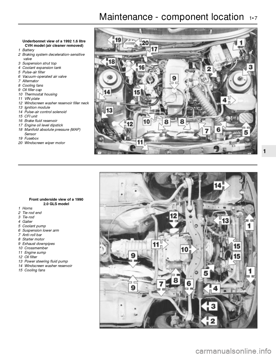
Front underside view of a 1990
2.0 GLS model
1 Horns
2 Tie-rod end
3 Tie-rod
4 Gaiter
5 Coolant pump
6 Suspension lower arm
7 Anti-roll bar
8 Starter motor
9 Exhaust downpipes
10 Crossmember
11 Engine sump
12 Oil filter
13 Power steering fluid pump
14 Windscreen washer reservoir
15 Cooling fans
Underbonnet view of a 1992 1.6 litre
CVH model (air cleaner removed)
1 Battery
2 Braking system deceleration-sensitive
valve
3 Suspension strut top
4 Coolant expansion tank
5 Pulse-air filter
6 Vacuum-operated air valve
7 Alternator
8 Cooling fans
9 Oil filler cap
10 Thermostat housing
11 VIN plate
12 Windscreen washer reservoir filler neck
13 Ignition module
14 Pulse-air control solenoid
15 CFI unit
16 Brake fluid reservoir
17 Engine oil level dipstick
18 Manifold absolute pressure (MAP)
Sensor
19 Fusebox
20 Windscreen wiper motor
Page 21 of 22
6Fit the new filter, ensuring that the arrows on
the filter body point in the direction of fuel flow.
7Tighten the clamp screw, and reconnect
the fuel inlet and outlet unions. Ensure that the
unions are correctly connected.
8Reconnect the battery negative lead, and
check the fuel line unions for leaks,
pressurising the system by switching the
ignition on and off several times.
All models except 2.0 litre SOHC
9Proceed as described for the 2.0 litre SOHCmodels, noting the following points.
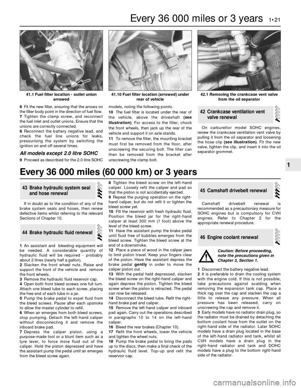
10The fuel filter is located under the rear of
the vehicle, above the driveshaft (see
illustration). For access to the filter, chock
the front wheels, then jack up the rear of the
vehicle and support it on axle stands.
11To remove the filter, the mounting bracket
must first be removed from the floor, after
unscrewing the securing bolt. The filter can
then be removed from the bracket after
unscrewing the clamp bolt.On carburettor model SOHC engines,
renew the crankcase ventilation vent valve by
pulling it from the oil separator and loosening
the hose clip (see illustration). Fit the new
valve, tighten the clip, and insert it into the oil
separator grommet.
42Crankcase ventilation vent
valve renewal
If in doubt as to the condition of any of the
brake system seals and hoses, then renew
defective items whilst referring to the relevant
Sections of Chapter 10.
1An assistant and bleeding equipment will
be needed. A considerable quantity of
hydraulic fluid will be required - probably
about 2 litres (nearly half a gallon).
2Slacken the front wheel nuts. Raise and
support the front of the vehicle and remove
the front wheels.
3Remove the hydraulic fluid reservoir cap.
4Open both front bleed screws one full turn.
Attach one bleed tube to each screw, placing
the free end of each tube in a jar.
5Pump the brake pedal to expel fluid from
the bleed screws. Pause after each upstroke
to allow the master cylinder to refill.
6When air emerges from both bleed screws,
stop pumping. Detach the left-hand caliper
without disconnecting it and remove the
inboard brake pad.
7Depress the caliper piston, using a
purpose-made tool or a blunt item such as a
tyre lever, to force more fluid out of the
caliper. Hold the piston depressed and have
the assistant pump the pedal until air emerges
from the bleed screw again.8Tighten the bleed screw on the left-hand
caliper. Loosely refit the caliper and pad so
that the piston is not accidentally ejected.
9Repeat the purging operation on the right-
hand caliper, but do not refit it or tighten the
bleed screw yet.
10Fill the reservoir with fresh hydraulic fluid.
Position the bleed jar for the right-hand
caliper at least 300 mm (1 foot) above the
level of the bleed screw.
11Have the assistant pump the brake pedal
until fluid free of bubbles emerges from the
bleed screw. Tighten the bleed screw at the
end of a downstroke.
12Place a piece of wood in the caliper jaws
to limit piston travel. Keep your fingers clear
of the piston. Have the assistant depress the
brake pedal gentlyin order to move the
caliper piston out.
13With the pedal held depressed, slacken
the bleed screw on the right-hand caliper and
again depress the piston. Tighten the bleed
screw when the piston is retracted. The pedal
can now be released.
14Disconnect the bleed tube. Refit the right-
hand brake pad and caliper.
15Remove the left-hand caliper and inboard
pad again. Carry out the operations described
in paragraphs 10 to 14 on the left-hand
caliper.
16Bleed the rear brakes (Chapter 10).
17Refit the front wheels, lower the vehicle
and tighten the wheel nuts.
18Pump the brake pedal to bring the pads
up to the discs, then make a final check of the
hydraulic fluid level. Top-up and refit the
reservoir cap.Camshaft drivebelt renewal is
recommended as a precautionary measure for
SOHC engines but is compulsory for CVH
engines. Refer to Chapter 2 for the
appropriate renewal procedure.
1Disconnect the battery negative lead.
2It is preferable to drain the cooling system
with the engine cold. If this is not possible,
take precautions against scalding when
removing the expansion tank cap. Place a
thick rag over the cap and slacken the cap a
little to release any pressure. When all
pressure has been released, carry on
unscrewing the cap and remove it.
3Early models have no radiator drain plug, so
the radiator must be drained by detaching the
bottom coolant hose from the outlet on the
right-hand side of the radiator. Later SOHC
models have a drain plug located in the base
of the left-hand radiator end tank, whilst all
CVH models have a drain plug in the
right-hand radiator end tank and DOHC
models have a plug to the bottom right-hand
side of the radiator.
46Engine coolant renewal
45Camshaft drivebelt renewal
44Brake hydraulic fluid renewal
43Brake hydraulic system seal
and hose renewal
Every 36 000 miles or 3 years 1•21
1
42.1 Removing the crankcase vent valve
from the oil separator41.10 Fuel filter location (arrowed) under
rear of vehicle41.1 Fuel filter location - outlet union
arrowed
Caution: Before proceeding,
note the precautions given in
Chapter 3, Section 1.
Every 36 000 miles (60 000 km) or 3 years
Page 22 of 22
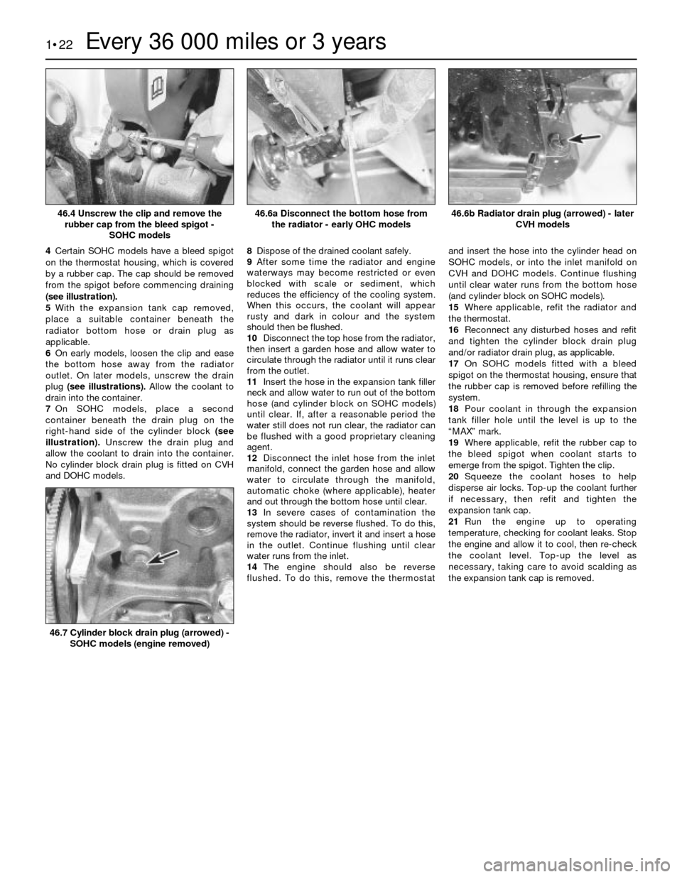
4Certain SOHC models have a bleed spigot
on the thermostat housing, which is covered
by a rubber cap. The cap should be removed
from the spigot before commencing draining
(see illustration).
5With the expansion tank cap removed,
place a suitable container beneath the
radiator bottom hose or drain plug as
applicable.
6On early models, loosen the clip and ease
the bottom hose away from the radiator
outlet. On later models, unscrew the drain
plug (see illustrations).Allow the coolant to
drain into the container.
7On SOHC models, place a second
container beneath the drain plug on the
right-hand side of the cylinder block (see
illustration).Unscrew the drain plug and
allow the coolant to drain into the container.
No cylinder block drain plug is fitted on CVH
and DOHC models.8Dispose of the drained coolant safely.
9After some time the radiator and engine
waterways may become restricted or even
blocked with scale or sediment, which
reduces the efficiency of the cooling system.
When this occurs, the coolant will appear
rusty and dark in colour and the system
should then be flushed.
10Disconnect the top hose from the radiator,
then insert a garden hose and allow water to
circulate through the radiator until it runs clear
from the outlet.
11Insert the hose in the expansion tank filler
neck and allow water to run out of the bottom
hose (and cylinder block on SOHC models)
until clear. If, after a reasonable period the
water still does not run clear, the radiator can
be flushed with a good proprietary cleaning
agent.
12Disconnect the inlet hose from the inlet
manifold, connect the garden hose and allow
water to circulate through the manifold,
automatic choke (where applicable), heater
and out through the bottom hose until clear.
13In severe cases of contamination the
system should be reverse flushed. To do this,
remove the radiator, invert it and insert a hose
in the outlet. Continue flushing until clear
water runs from the inlet.
14The engine should also be reverse
flushed. To do this, remove the thermostatand insert the hose into the cylinder head on
SOHC models, or into the inlet manifold on
CVH and DOHC models. Continue flushing
until clear water runs from the bottom hose
(and cylinder block on SOHC models).
15Where applicable, refit the radiator and
the thermostat.
16Reconnect any disturbed hoses and refit
and tighten the cylinder block drain plug
and/or radiator drain plug, as applicable.
17On SOHC models fitted with a bleed
spigot on the thermostat housing, ensure that
the rubber cap is removed before refilling the
system.
18Pour coolant in through the expansion
tank filler hole until the level is up to the
“MAX” mark.
19Where applicable, refit the rubber cap to
the bleed spigot when coolant starts to
emerge from the spigot. Tighten the clip.
20Squeeze the coolant hoses to help
disperse air locks. Top-up the coolant further
if necessary, then refit and tighten the
expansion tank cap.
21Run the engine up to operating
temperature, checking for coolant leaks. Stop
the engine and allow it to cool, then re-check
the coolant level. Top-up the level as
necessary, taking care to avoid scalding as
the expansion tank cap is removed.
1•22Every 36 000 miles or 3 years
46.4 Unscrew the clip and remove the
rubber cap from the bleed spigot -
SOHC models46.6b Radiator drain plug (arrowed) - later
CVH models
46.7 Cylinder block drain plug (arrowed) -
SOHC models (engine removed)
46.6a Disconnect the bottom hose from
the radiator - early OHC models