jacking points FORD SIERRA 1986 1.G Suspension And Steering Workshop Manual
[x] Cancel search | Manufacturer: FORD, Model Year: 1986, Model line: SIERRA, Model: FORD SIERRA 1986 1.GPages: 20, PDF Size: 0.94 MB
Page 4 of 20

6Where applicable, remove the brake pipes
from the clips on the crossmember, taking
care not to strain them, and detach any cables
or electrical leads which may be secured with
clips or cable-ties, noting their positions.
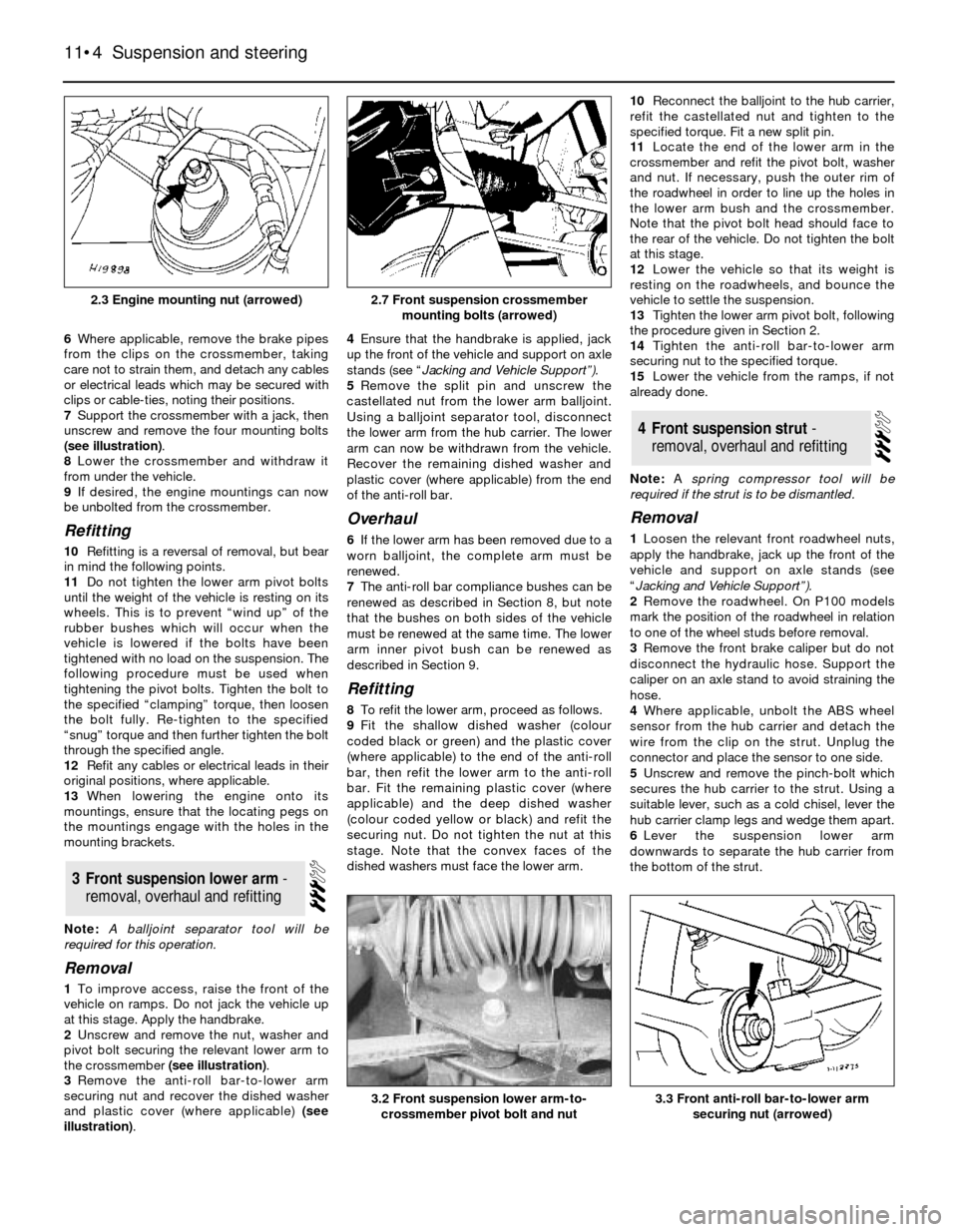
7Support the crossmember with a jack, then
unscrew and remove the four mounting bolts
(see illustration).
8Lower the crossmember and withdraw it
from under the vehicle.
9If desired, the engine mountings can now
be unbolted from the crossmember.
Refitting
10Refitting is a reversal of removal, but bear
in mind the following points.
11Do not tighten the lower arm pivot bolts
until the weight of the vehicle is resting on its
wheels. This is to prevent “wind up” of the
rubber bushes which will occur when the
vehicle is lowered if the bolts have been
tightened with no load on the suspension. The
following procedure must be used when
tightening the pivot bolts. Tighten the bolt to
the specified “clamping” torque, then loosen
the bolt fully. Re-tighten to the specified
“snug” torque and then further tighten the bolt
through the specified angle.
12Refit any cables or electrical leads in their
original positions, where applicable.
13When lowering the engine onto its
mountings, ensure that the locating pegs on
the mountings engage with the holes in the
mounting brackets.
Note: A balljoint separator tool will be
required for this operation.
Removal
1To improve access, raise the front of the
vehicle on ramps. Do not jack the vehicle up
at this stage. Apply the handbrake.
2Unscrew and remove the nut, washer and
pivot bolt securing the relevant lower arm to
the crossmember (see illustration).
3Remove the anti-roll bar-to-lower arm
securing nut and recover the dished washer
and plastic cover (where applicable) (see
illustration).4Ensure that the handbrake is applied, jack
up the front of the vehicle and support on axle
stands (see “Jacking and Vehicle Support”).
5Remove the split pin and unscrew the
castellated nut from the lower arm balljoint.
Using a balljoint separator tool, disconnect
the lower arm from the hub carrier. The lower
arm can now be withdrawn from the vehicle.
Recover the remaining dished washer and
plastic cover (where applicable) from the end
of the anti-roll bar.
Overhaul
6If the lower arm has been removed due to a
worn balljoint, the complete arm must be
renewed.
7The anti-roll bar compliance bushes can be
renewed as described in Section 8, but note
that the bushes on both sides of the vehicle
must be renewed at the same time. The lower
arm inner pivot bush can be renewed as
described in Section 9.
Refitting
8To refit the lower arm, proceed as follows.
9Fit the shallow dished washer (colour
coded black or green) and the plastic cover
(where applicable) to the end of the anti-roll
bar, then refit the lower arm to the anti-roll
bar. Fit the remaining plastic cover (where
applicable) and the deep dished washer
(colour coded yellow or black) and refit the
securing nut. Do not tighten the nut at this
stage. Note that the convex faces of the
dished washers must face the lower arm.10Reconnect the balljoint to the hub carrier,
refit the castellated nut and tighten to the
specified torque. Fit a new split pin.
11Locate the end of the lower arm in the
crossmember and refit the pivot bolt, washer
and nut. If necessary, push the outer rim of
the roadwheel in order to line up the holes in
the lower arm bush and the crossmember.
Note that the pivot bolt head should face to
the rear of the vehicle. Do not tighten the bolt
at this stage.
12Lower the vehicle so that its weight is
resting on the roadwheels, and bounce the
vehicle to settle the suspension.
13Tighten the lower arm pivot bolt, following
the procedure given in Section 2.
14Tighten the anti-roll bar-to-lower arm
securing nut to the specified torque.
15Lower the vehicle from the ramps, if not
already done.
Note: A spring compressor tool will be
required if the strut is to be dismantled.
Removal
1Loosen the relevant front roadwheel nuts,
apply the handbrake, jack up the front of the
vehicle and support on axle stands (see
“Jacking and Vehicle Support”).
2Remove the roadwheel. On P100 models
mark the position of the roadwheel in relation
to one of the wheel studs before removal.
3Remove the front brake caliper but do not
disconnect the hydraulic hose. Support the
caliper on an axle stand to avoid straining the
hose.
4Where applicable, unbolt the ABS wheel
sensor from the hub carrier and detach the
wire from the clip on the strut. Unplug the
connector and place the sensor to one side.
5Unscrew and remove the pinch-bolt which
secures the hub carrier to the strut. Using a
suitable lever, such as a cold chisel, lever the
hub carrier clamp legs and wedge them apart.
6Lever the suspension lower arm
downwards to separate the hub carrier from
the bottom of the strut.
4Front suspension strut -
removal, overhaul and refitting
3Front suspension lower arm -
removal,overhaul and refitting
11•4Suspension and steering
2.3 Engine mounting nut (arrowed)
3.3 Front anti-roll bar-to-lower arm
securing nut (arrowed)3.2 Front suspension lower arm-to-
crossmember pivot bolt and nut
2.7 Front suspension crossmember
mounting bolts (arrowed)
Page 5 of 20

7Working in the engine compartment,
unscrew the strut upper mounting nut, at the
same time supporting the strut from below.
Use a 6 mm Allen key inserted in the end of
the strut piston rod to prevent the rod from
turning as the upper mounting nut is
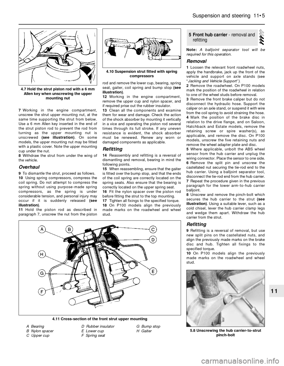
unscrewed (see illustration). On some
models, the upper mounting nut may be fitted
with a plastic cover. Note the upper mounting
cup under the nut.
8Withdraw the strut from under the wing of
the vehicle.
Overhaul
9To dismantle the strut, proceed as follows.
10Using spring compressors, compress the
coil spring. Do not attempt to compress the
spring without using purpose-made spring
compressors, as the spring is under
considerable tension, and personal injury may
occur if it is suddenly released (see
illustration).
11Hold the piston rod as described in
paragraph 7, unscrew the nut from the pistonrod and remove the lower cup, bearing, spring
seat, gaiter, coil spring and bump stop (see
illustration).
12Working in the engine compartment,
remove the upper cup and nylon spacer, and
if required prise out the rubber insulator.
13Clean all the components and examine
them for wear and damage. Check the action
of the shock absorber by mounting it vertically
in a vice and operating the piston rod several
times through its full stroke. If any uneven
resistance is evident, the shock absorber
must be renewed. Renew any worn or
damaged components as applicable.
Refitting
14Reassembly and refitting is a reversal of
dismantling and removal, bearing in mind the
following points.
15When reassembling, ensure that the gaiter
is fitted over the bump stop, and that the ends
of the coil spring are correctly located on the
spring seats. Also ensure that the bearing is
correctly located on the upper spring seat.
16Fit the nylon spacer over the piston rod
before fitting the strut to the top mounting.
17Tighten all fixings to the specified torque.
18On P100 models align the previously
made marks on the roadwheel and wheel
stud.Note: A balljoint separator tool will be
required for this operation.
Removal
1Loosen the relevant front roadwheel nuts,
apply the handbrake, jack up the front of the
vehicle and support on axle stands (see
“Jacking and Vehicle Support”).
2Remove the roadwheel. On P100 models
mark the position of the roadwheel in relation
to one of the wheel studs before removal.
3Remove the front brake caliper but do not
disconnect the hydraulic hose. Support the
caliper on an axle stand, or suspend it with wire
from the coil spring to avoid straining the hose.
4Mark the position of the brake disc in
relation to the drive flange, and on Saloon,
Hatchback and Estate models, remove the
retaining screw or spire washer(s), as
applicable, and remove the disc. On P100
models, unscrew the five retaining nuts and
remove the wheel adapter plate and disc.
5Where applicable, unbolt the ABS wheel
sensor from the hub carrier and unplug the
wiring connector. Place the sensor to one side.
6Remove the split pin and unscrew the
castellated nut securing the tie-rod end to the
hub carrier. Using a balljoint separator tool,
disconnect the tie-rod end from the hub carrier.
7Repeat the procedure given in the previous
paragraph for the lower arm-to-hub carrier
balljoint.
8Unscrew and remove the pinch-bolt which
secures the hub carrier to the strut (see
illustration). Using a suitable lever, such as a
cold chisel, lever the hub carrier clamp legs
and wedge them apart. Withdraw the hub
carrier from the strut.
Refitting
9Refitting is a reversal of removal, but use
new split pins on the castellated nuts, and
align the previously made marks on the brake
disc and hub. Tighten all fixings to the
specified torque.
10On P100 models align the previously
made marks on the roadwheel and wheel
stud.
5Front hub carrier -removaland
refitting
Suspension and steering 11•5
11
5.8 Unscrewing the hub carrier-to-strut
pinch-bolt
4.11 Cross-section of the front strut upper mounting
A Bearing
B Nylon spacer
C Upper cupD Rubber insulator
E Lower cup
F Spring seatG Bump stop
H Gaiter
4.10 Suspension strut fitted with spring
compressors
4.7 Hold the strut piston rod with a 6 mm
Allen key when unscrewing the upper
mounting nut
Page 11 of 20

nuts, and it is important to note that where
this type of nut is fitted, the left-hand nut has
a left-hand thread, ie. it is undone in a
clockwise direction. Before loosening the nut,
ensure that the handbrake is applied, and
chock the relevant rear wheel. A suitable
extension bar will be required, as the nut is
extremely tight.
2Loosen the rear roadwheel nuts on the side
concerned, chock the front wheels, and jack
up the rear of the vehicle and support on axle
stands (see “Jacking and Vehicle Support”).
Remove the rear roadwheel.
3Remove the brake drum retaining spire
washer(s) from the wheel stud(s) and remove
the brake drum. Ensure that the handbrake is
released before removing the brake drum,
otherwise the drum will be held in place by the
clamping action of the brake shoes.
4Remove the two nylon fasteners, and
remove the plastic shield from the rear of the
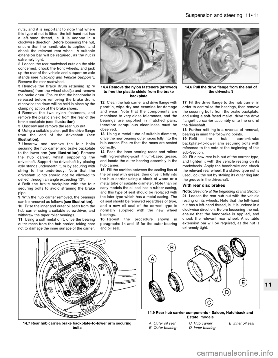
brake backplate (see illustration).
5Unscrew and remove the rear hub nut.
6Using a suitable puller, pull the drive flange
from the end of the driveshaft (see
illustration).
7Unscrew and remove the four bolts
securing the hub carrier and brake backplate
to the lower arm (see illustration). Remove
the hub carrier, whilst supporting the
driveshaft. Support the driveshaft by placing
axle stands underneath it, or by securing with
string to the underbody. Note that the
driveshaft joints should not be allowed to
deflect through an angle exceeding 13º.
8Refit the brake backplate with the four
securing bolts to avoid straining the brake
pipe.
9With the hub carrier removed, the bearings
can be renewed as follows (see illustration).
10Prise the inner and outer oil seals from the
hub carrier using a suitable screwdriver, and
withdraw the taper roller bearings.
11Using a soft metal drift, drive the bearing
outer races from the hub carrier, taking care
not to damage the inner surface of the carrier.12Clean the hub carrier and drive flange with
paraffin, wipe dry and examine for damage
and wear. Note that the components are
machined to very close tolerances, and the
bearings are supplied in matched pairs,
therefore scrupulous cleanliness must be
observed.
13Using a metal tube of suitable diameter,
drive the new bearing outer races fully into the
hub carrier. Ensure that the races are seated
correctly.
14Pack the inner bearing races and rollers
with high-melting-point lithium-based grease,
and locate the outer bearing assembly in the
hub carrier.
15Fill the cavities between the sealing lips of
the oil seal with grease, then drive it fully into
the hub carrier using a block of wood or a
metal tube of suitable diameter. Note than on
early models the oil seal has a rubber casing,
and this type of seal should be replaced with
the later type which has a metal casing. The
oil seal should be renewed regardless of type,
and a new oil seal of the correct type is
normally supplied with the new wheel
bearings.
16Repeat the procedure shown in
paragraphs 14 and 15 for the outer bearing
and oil seal.17Fit the drive flange to the hub carrier in
order to centralise the bearings, then remove
the securing bolts from the brake backplate,
and using a soft-faced mallet, drive the drive
flange/hub carrier assembly onto the end of
the driveshaft.
18Further refitting is a reversal of removal,
bearing in mind the following points.
19Refit the hub carrier/brake
backplate-to-lower arm securing bolts with
reference to the note at the beginning of this
sub-Section.
20Fit a new rear hub nut of the correct type,
and tighten it with the vehicle resting on its
roadwheels. Apply the handbrake and chock
the relevant rear wheel. If a staked type nut is
used, lock the nut by staking its outer ring into
the groove in the driveshaft.
With rear disc brakes
Note: See note.at the beginning of this Section
21Loosen the rear hub nut with the vehicle
resting on its wheels. Note that the left-hand
nut has a left-hand thread, ie. it is undone in a
clockwise direction. Before loosening the nut,
ensure that the handbrake is applied, and
chock the relevant rear wheel. A suitable
extension bar will be required, as the nut is
extremely tight.
Suspension and steering 11•11
11
14.6 Pull the drive flange from the end of
the driveshaft
14.9 Rear hub carrier components - Saloon, Hatchback and
Estate models
A Outer oil seal
B Outer bearingC Hub carrier
D Inner bearingE Inner oil seal14.7 Rear hub carrier/brake backplate-to-lower arm securing
bolts
14.4 Remove the nylon fasteners (arrowed)
to free the plastic shield from the brake
backplate