dimensions FORD SIERRA 1987 2.G DOHC Engine Workshop Manual
[x] Cancel search | Manufacturer: FORD, Model Year: 1987, Model line: SIERRA, Model: FORD SIERRA 1987 2.GPages: 18, PDF Size: 0.9 MB
Page 16 of 18

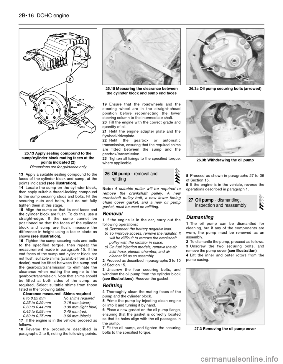
13Apply a suitable sealing compound to the
faces of the cylinder block and sump, at the
points indicated (see illustration).
14Locate the sump on the cylinder block,
then apply suitable thread-locking compound
to the sump securing studs and bolts. Fit the
securing nuts and bolts, but do not fully
tighten them at this stage.
15Align the sump so that its end faces and
the cylinder block are flush. To do this, use a
straight-edge. If the sump cannot be
positioned so that the faces of the cylinder
block and sump are flush, measure the
difference in height using a feeler blade as
shown (see illustration).
16Tighten the sump securing nuts and bolts
to the specified torque, then repeat the
measurement made in paragraph 15. If the
end faces of the sump and cylinder block are
not flush, suitable shims (available from a Ford
dealer) must be fitted between the sump and
the gearbox/transmission to eliminate the
clearance when mating the engine to the
gearbox/transmission. Note that shims should
be fitted at both sides of the sump, as
required. Select suitable shims from those
listed in the following table:
Clearance measuredShims required
0 to 0.25 mmNo shims required
0.25 to 0.29 mm0.15 mm (silver)
0.30 to 0.44 mm0.30 mm (light blue)
0.45 to 0.59 mm0.45 mm (red)
0.60 to 0.75 mm0.60 mm (black)
17If the engine is in the vehicle, proceed as
follows.
18Reverse the procedure described in
paragraphs 2 to 8, noting the following points.19Ensure that the roadwheels and the
steering wheel are in the straight-ahead
position before reconnecting the lower
steering column to the intermediate shaft.
20Fill the engine with the correct grade and
quantity of oil.
21Refit the engine adapter plate and the
flywheel/driveplate.
22Refit the gearbox or automatic
transmission, ensuring that the required shims
are fitted between the sump and the
gearbox/transmission.
23Tighten all fixings to the specified torque,
where applicable.
Note: A suitable puller will be required to
remove the crankshaft pulley. A new
crankshaft pulley bolt, a new lower timing
chain cover gasket, and a new oil pump
gasket, must be used on refitting.
Removal
1If the engine is in the car, carry out the
following operations:
a)Disconnect the battery negative lead.
b)To improve access, remove the radiator. It
will be difficult to remove the crankshaft
pulley with the radiator in place.
c)On fuel injection models, remove the air
inlet hose, plenum chamber, and air
cleaner lid as an assembly.
2Proceed as described in paragraphs 3 to 10
of Section 15.
3Unscrew the four securing bolts, and
withdraw the oil pump from the cylinder block
(see illustrations). Recover the gasket.
Refitting
4Thoroughly clean the mating faces of the
pump and the cylinder block.
5Prime the pump by injecting clean engine
oil into it and turning it by hand.
6Place a new gasket on the oil pump flange,
ensuring that the gasket is correctly located
so that its holes align with the oil passages in
the pump.
7Fit the oil pump, and tighten the securing
bolts to the specified torque.8Proceed as shown in paragraphs 27 to 39
of Section 15.
9If the engine is in the vehicle, reverse the
operations described in paragraph 1.
Dismantling
1The oil pump can be dismantled for
cleaning, but if any of the components are
worn, the pump must be renewed as an
assembly.
2To dismantle the pump, proceed as follows.
3Unscrew the two securing bolts, and
remove the pump cover (see illustration).
4Lift the inner and outer rotors from the
pump casing.
27Oil pump - dismantling,
inspection and reassembly
26Oil pump - removal and
refitting
2B•16DOHC engine
25.13 Apply sealing compound to the
sump/cylinder block mating faces at the
points indicated (2)
Dimensions are for guidance only
26.3b Withdrawing the oil pump
26.3a Oil pump securing bolts (arrowed)25.15 Measuring the clearance between
the cylinder block and sump end faces
27.3 Removing the oil pump cover