bulb FORD SIERRA 1990 2.G Body Electrical System Workshop Manual
[x] Cancel search | Manufacturer: FORD, Model Year: 1990, Model line: SIERRA, Model: FORD SIERRA 1990 2.GPages: 25, PDF Size: 1.7 MB
Page 1 of 25

Chapter 13
Body electrical system
Anti-theft alarm - location, removal and refitting . . . . . . . . . . . . . . . .51
Auxiliary warning system components - location, testing, removal and
refitting . . . . . . . . . . . . . . . . . . . . . . . . . . . . . . . . . . . . . . . . . . . . . .23
Brake lamp switch - renewal . . . . . . . . . . . . . . . . . . . . . . . . . . . . . . .15
Central door locking components - operation, removal and refitting .50
Cigarette lighter - renewal . . . . . . . . . . . . . . . . . . . . . . . . . . . . . . . . .18
Clock - removal and refitting . . . . . . . . . . . . . . . . . . . . . . . . . . . . . . .19
Courtesy lamp and luggage compartment lamp - renewal . . . . . . . .25
Courtesy lamp switch - renewal . . . . . . . . . . . . . . . . . . . . . . . . . . . . .12
Direction indicator and hazard warning flasher switch assembly -
renewal . . . . . . . . . . . . . . . . . . . . . . . . . . . . . . . . . . . . . . . . . . . . . . .5
Direction indicator/hazard warning flasher relay - renewal . . . . . . . . .6
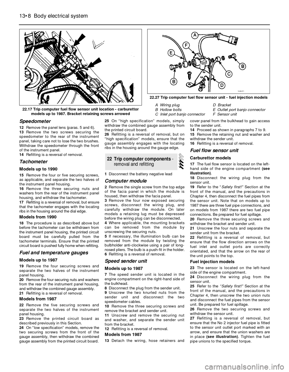
Electrical door mirror switch - removal and refitting . . . . . . . . . . . . .10
Electrical fault finding - general information . . . . . . . . . . . . . . . . . . . . .2
Electric sunroof components - removal and refitting . . . . . . . . . . . . .17
Electric window components - removal and refitting . . . . . . . . . . . . .49
Exterior lamp bulbs - renewal . . . . . . . . . . . . . . . . . . . . . . . . . . . . . . .48
Facia panel switches - removal and refitting . . . . . . . . . . . . . . . . . . . .9
Front direction indicator lamp unit - removal and refitting . . . . . . . . .44
Front direction indicator side repeater lamp - removal and refitting . .45
Front foglamps - removal and refitting . . . . . . . . . . . . . . . . . . . . . . . .46
Fuses and relays - location and renewal . . . . . . . . . . . . . . . . . . . . . . .3
General information and precautions . . . . . . . . . . . . . . . . . . . . . . . . .1
Handbrake “on” warning lamp switch - renewal . . . . . . . . . . . . . . . .14
Headlamps - alignment . . . . . . . . . . . . . . . . . . . . . . . . . . . . . . . . . . .42
Headlamp unit - removal and refitting . . . . . . . . . . . . . . . . . . . . . . . .41
Headlamp wiper motor - removal and refitting . . . . . . . . . . . . . . . . . .40
Horn - removal and refitting . . . . . . . . . . . . . . . . . . . . . . . . . . . . . . . .29
Horn switch assembly - removal and refitting . . . . . . . . . . . . . . . . . .11
Ignition switch and lock barrel - removal and refitting . . . . . . . . . . . . .4
Instrument panel - removal and refitting . . . . . . . . . . . . . . . . . . . . . .20Instrument panel components - removal and refitting . . . . . . . . . . . .21
Integral heated rear window/radio aerial amplifier - removal and
refitting . . . . . . . . . . . . . . . . . . . . . . . . . . . . . . . . . . . . . . . . . . . . . .54
Interior lamp bulbs - renewal . . . . . . . . . . . . . . . . . . . . . . . . . . . . . . .27
Lighting and wash/wipe switch assembly - renewal. . . . . . . . . . . . . . .7
“Lights-on” warning module - renewal . . . . . . . . . . . . . . . . . . . . . . . .24
Loudspeakers - removal and refitting . . . . . . . . . . . . . . . . . . . . . . . . .55
Luggage compartment lamp switch - removal and refitting . . . . . . .13
Map reading lamp - removal and refitting . . . . . . . . . . . . . . . . . . . . .26
Oil pressure warning lamp switch - renewal . . . . . . . . . . . . . . . . . . . .16
Radio aerial (exterior-mounted) - removal and refitting . . . . . . . . . . .53
Radio/cassette player - removal and refitting . . . . . . . . . . . . . . . . . . .57
Radio/cassette player power amplifier - removal and refitting . . . . . .56
Rear lamp unit - removal and refitting . . . . . . . . . . . . . . . . . . . . . . . .43
Rear number plate lamp - removal and refitting . . . . . . . . . . . . . . . . .47
Rear window washer fluid reservoir - removal and refitting . . . . . . . .39
Rear window washer pump - removal and refitting . . . . . . . . . . . . . .38
Rear window wiper motor - removal and refitting . . . . . . . . . . . . . . .37
Reversing lamp switch - renewal . . . . . . . . . . . . . . . . . . . . . . . . . . . . .8
Seat heating pad - removal and refitting . . . . . . . . . . . . . . . . . . . . . .52
Speedometer cable - removal and refitting . . . . . . . . . . . . . . . . . . . .30
Trip computer components - removal and refitting . . . . . . . . . . . . . .22
Underbonnet lamp - removal, refitting and bulb renewal . . . . . . . . . .28
Washer nozzles - removal and refitting . . . . . . . . . . . . . . . . . . . . . . .33
Windscreen/headlamp washer fluid reservoir - removal and refitting . .36
Windscreen/headlamp washer pump - removal and refitting . . . . . .35
Windscreen wiper motor and linkage - removal and refitting . . . . . . .34
Wiper arms - removal and refitting . . . . . . . . . . . . . . . . . . . . . . . . . . .32
Wiper blades - renewal . . . . . . . . . . . . . . . . . . . . . . . . . . . . . . . . . . . .31
Wiring diagrams - general information . . . . . . . . . . . . . . . . . . . . . . . .58
13•1
Contents
13Easy,suitable for
novice with little
experienceFairly easy,suitable
for beginner with
some experienceFairly difficult,
suitable for competent
DIY mechanic
Difficult,suitable for
experienced DIY
mechanicVery difficult,
suitable for expert
DIY or professional
Degrees of difficulty
Page 2 of 25
System type . . . . . . . . . . . . . . . . . . . . . . . . . . . . . . . . . . . . . . . . . . .12 volt, negative earth
BulbsFittingsWattage
Halogen headlamps . . . . . . . . . . . . . . . . . . . . . . . . . . . . . . . . . . . . . . . .H460/55
Auxiliary driving lamps . . . . . . . . . . . . . . . . . . . . . . . . . . . . . . . . . . . . . .H355
Front foglamps . . . . . . . . . . . . . . . . . . . . . . . . . . . . . . . . . . . . . . . . . . . .H355
Side lamps . . . . . . . . . . . . . . . . . . . . . . . . . . . . . . . . . . . . . . . . . . . . . . .Glass base5
Direction indicator lamps . . . . . . . . . . . . . . . . . . . . . . . . . . . . . . . . . . . .Bayonet21
Brake/tail lamps . . . . . . . . . . . . . . . . . . . . . . . . . . . . . . . . . . . . . . . . . . .Bayonet21/4
Reversing lamp(s) . . . . . . . . . . . . . . . . . . . . . . . . . . . . . . . . . . . . . . . . . .Bayonet21
Rear foglamp(s) . . . . . . . . . . . . . . . . . . . . . . . . . . . . . . . . . . . . . . . . . . . .Bayonet21
Rear number plate lamps . . . . . . . . . . . . . . . . . . . . . . . . . . . . . . . . . . . .Glass base5
Luggage compartment lamp . . . . . . . . . . . . . . . . . . . . . . . . . . . . . . . . .Bayonet10
Underbonnet lamp . . . . . . . . . . . . . . . . . . . . . . . . . . . . . . . . . . . . . . . . .Bayonet10
Courtesy lamp(s) . . . . . . . . . . . . . . . . . . . . . . . . . . . . . . . . . . . . . . . . . . .Bayonet10
Map reading lamps . . . . . . . . . . . . . . . . . . . . . . . . . . . . . . . . . . . . . . . . .Glass base5
Vanity mirror illumination lamp . . . . . . . . . . . . . . . . . . . . . . . . . . . . . . . .Festoon3
Glove compartment lamp . . . . . . . . . . . . . . . . . . . . . . . . . . . . . . . . . . . .Glass base3
Ashtray lamp . . . . . . . . . . . . . . . . . . . . . . . . . . . . . . . . . . . . . . . . . . . . . .Glass base1.2
Warning lamps . . . . . . . . . . . . . . . . . . . . . . . . . . . . . . . . . . . . . . . . . . . .Glass base1.2 or 2.5
Instrument illumination lamps . . . . . . . . . . . . . . . . . . . . . . . . . . . . . . . . .Glass base1.2 or 2.5
Heater control illumination lamp . . . . . . . . . . . . . . . . . . . . . . . . . . . . . . .Glass base1
Automatic transmission gear selector lamp . . . . . . . . . . . . . . . . . . . . . .Bayonet1.2
Clock illumination lamp . . . . . . . . . . . . . . . . . . . . . . . . . . . . . . . . . . . . .Bayonet1.4
Cigarette lighter lamp . . . . . . . . . . . . . . . . . . . . . . . . . . . . . . . . . . . . . . .Glass base1.2
Torque wrench settingsNmlbf ft
Trip computer fuel flow sensor unit fuel pipe unions . . . . . . . . . . . . . . .14 to 1710 to 13
General information
The electrical system is of the 12 volt.
negative earth type. Electricity is generated by
an alternator, belt-driven from the crankshaft
pulley. A lead-acid storage battery provides a
reserve of power for starting and when the
demands of the system temporarily exceed
the alternator output.
The battery negative terminal is connected
to “earth” - vehicle metal - and most electrical
system components are wired so that they
only receive a positive feed, the current
returning via vehicle metal. This means that
the component mounting forms part of the
circuit. Loose or corroded mountings can
therefore cause apparent electrical faults.
Many semiconductor devices are used in
the electrical system, both in the “black
boxes” which control vehicle functions and in
other components. Semiconductors are very
sensitive to excessive (or wrong polarity)
voltage, and to extremes of heat. Observe the
appropriate precautions to avoid damage.
Precautions
It is necessary to take extra care when
working on the electrical system to avoid
damage to semi-conductor devices (diodes
and transistors), and to avoid the risk of
personal injury. In addition to the precautions
given in the
“Safety first!” Section at the
beginning of this manual, take note of the
following points when working on the system.
Always remove rings, watches, etc before
working on the electrical system. Even withthe battery disconnected, capacitive
discharge could occur if a component live
terminal is earthed through a metal object.
This could cause a shock or nasty burn.
Do not reverse the battery connections.
Components such as the alternator or any
other having semi-conductor circuitry could
be irreparably damaged.
If the engine is being started using jump
leads and a slave battery, connect the
batteries positive to positive and negative to
negative. This also applies when connecting a
battery charger.
Never disconnect the battery terminals, or
alternator multi-plug connector, when the
engine is running.
The battery leads and alternator multi-plug
must be disconnected before carrying out any
electric welding on the car.
Never use an ohmmeter of the type
incorporating a hand cranked generator for
circuit or continuity testing.
Note:Refer to the precautions given in “Safety
first!” and in Section 1 of this Chapter before
starting work. The following tests relate to testing
of the main electrical circuits, and should not be
used to test delicate electronic circuits (such as
anti-lock braking systems), particularly where an
electronic control unit (ECU) is involved.General
1A typical electrical circuit consists of an
electrical component, any switches, relays,
motors, fuses, fusible links or circuit breakers
related to that component, and the wiring andconnectors which link the component to both
the battery and the chassis. To help to pinpoint a
problem in an electrical circuit, wiring diagrams
are included at the end of this Chapter.
2Before attempting to diagnose an electrical
fault, first study the appropriate wiring
diagram, to obtain a more complete
understanding of the components included in
the particular circuit concerned. The possible
sources of a fault can be narrowed down by
noting whether other components related to
the circuit are operating properly. If several
components or circuits fail at one time, the
problem is likely to be related to a shared fuse
or earth connection.
3Electrical problems usually stem from
simple causes, such as loose or corroded
connections, a faulty earth connection, a
blown fuse, a melted fusible link, or a faulty
relay. Visually inspect the condition of all
fuses, wires and connections in a problem
circuit before testing the components. Use
the wiring diagrams to determine which
terminal connections will need to be checked,
in order to pinpoint the trouble-spot.
4The basic tools required for electrical fault-
finding include: a circuit tester or voltmeter (a
12-volt bulb with a set of test leads can also
be used for certain tests), a self-powered test
light (sometimes known as a continuity tester),
an ohmmeter (to measure resistance), a
battery and set of test leads, and a jumper
wire, preferably with a circuit breaker or fuse
incorporated, which can be used to bypass
suspect wires or electrical components.
Before attempting to locate a problem with
test instruments, use the wiring diagram to
determine where to make the connections.
2Electrical fault-finding - general
information
1General information and
precautions
13•2Body electrical system
Specifications
Page 3 of 25
5To find the source of an intermittent wiring
fault (usually due to a poor or dirty
connection, or damaged wiring insulation), an
integrity test can be performed on the wiring,
which involves moving the wiring by hand, to
see if the fault occurs as the wiring is moved.
It should be possible to narrow down the
source of the fault to a particular section of
wiring. This method of testing can be used in
conjunction with any of the tests described in
the following sub-Sections.
6Apart from problems due to poor
connections, two basic types of fault can
occur in an electrical circuit - open-circuit, or
short-circuit.
7Open-circuit faults are caused by a break
somewhere in the circuit, which prevents
current from flowing. An open-circuit fault will
prevent a component from working, but will
not cause the relevant circuit fuse to blow.
8Short-circuit faults are caused by a “short”
somewhere in the circuit, which allows the
current flowing in the circuit to “escape” along
an alternative route, usually to earth. Short-
circuit faults are normally caused by a
breakdown in wiring insulation, which allows a
feed wire to touch either another wire, or an
earthed component such as the bodyshell. A
short-circuit fault will normally cause the
relevant circuit fuse to blow.
Note: A short-circuit that occurs in the wiring
between a circuit’s battery supply and its fuse
will not cause the fuse in that particular circuit
to blow. This part of the circuit is unprotected
- bear this in mind when fault-finding on the
vehicle’s electrical system.
Finding an open-circuit
9To check for an open-circuit, connect one
lead of a circuit tester or voltmeter to either
the negative battery terminal or a known good
earth.
10Connect the other lead to a connector in
the circuit being tested, preferably nearest to
the battery or fuse.
11Switch on the circuit, bearing in mind that
some circuits are live only when the ignition
switch is moved to a particular position.
12If voltage is present (indicated either by
the tester bulb lighting or a voltmeter reading,
as applicable), this means that the section of
the circuit between the relevant connector
and the battery is problem-free.
13Continue to check the remainder of the
circuit in the same fashion.
14When a point is reached at which no
voltage is present, the problem must lie
between that point and the previous test point
with voltage. Most problems can be traced to
a broken, corroded or loose connection.
Finding a short-circuit
15To check for a short-circuit, first
disconnect the load(s) from the circuit (loads
are the components which draw current from
a circuit, such as bulbs, motors, heating
elements, etc).
16Remove the relevant fuse from the circuit,
and connect a circuit tester or voltmeter to the
fuse connections.17Switch on the circuit, bearing in mind that
some circuits are live only when the ignition
switch is moved to a particular position.
18If voltage is present (indicated either by
the tester bulb lighting or a voltmeter reading,
as applicable), this means that there is a
short-circuit.
19If no voltage is present, but the fuse still
blows with the load(s) connected, this
indicates an internal fault in the load(s).
Finding an earth fault
20The battery negative terminal is connected
to “earth” - the metal of the
engine/transmission and the car body - and
most systems are wired so that they only
receive a positive feed, the current returning via
the metal of the car body. This means that the
component mounting and the body form part
of that circuit. Loose or corroded mountings
can therefore cause a range of electrical faults,
ranging from total failure of a circuit, to a
puzzling partial fault. In particular, lights may
shine dimly (especially when another circuit
sharing the same earth point is in operation),
motors (eg wiper motors or the radiator cooling
fan motor) may run slowly, and the operation of
one circuit may have an apparently-unrelated
effect on another. Note that on many vehicles,
earth straps are used between certain
components, such as the engine/transmission
and the body, usually where there is no metal-
to-metal contact between components, due to
flexible rubber mountings, etc.
21To check whether a component is
properly earthed, disconnect the battery, and
connect one lead of an ohmmeter to a known
good earth point. Connect the other lead to
the wire or earth connection being tested. The
resistance reading should be zero; if not,
check the connection as follows.
22If an earth connection is thought to be
faulty, dismantle the connection, and clean
back to bare metal both the bodyshell and the
wire terminal, or the component’s earth
connection mating surface. Be careful to
remove all traces of dirt and corrosion, then
use a knife to trim away any paint, so that a
clean metal-to-metal joint is made. On
reassembly, tighten the joint fasteners
securely; if a wire terminal is being refitted,
use serrated washers between the terminaland the bodyshell, to ensure a clean and
secure connection. When the connection is
remade, prevent the onset of corrosion in the
future by applying a coat of petroleum jelly or
silicone-based grease, or by spraying on (at
regular intervals) a proprietary ignition sealer.Location
1The main fuses and relays are located in a
box in the engine compartment on the right-
hand side of the bulkhead. The circuits
protected are identified by symbols on the
underside of the fusebox cover. On certain
models, additional relays and fuses are located
in various positions beneath the facia panels. If
uncertain of the location of an auxiliary relay or
fuse, it is suggested that a Ford dealer is
consulted, as the relay and fuse locations vary
substantially depending on model.
Renewal
2Always renew a fuse with one of identical
rating and never renew it more than once
without finding the source of the trouble
(usually a short circuit). Always switch off the
ignition before renewing a fuse or relay, and
when renewing the wiper motor fuse keep the
hands clear of the wiper linkage as it may
return to the parked position. Note that the
fuses are colour-coded as follows:
10ARed
15ABlue
20AYellow
25ANatural
10AGreen
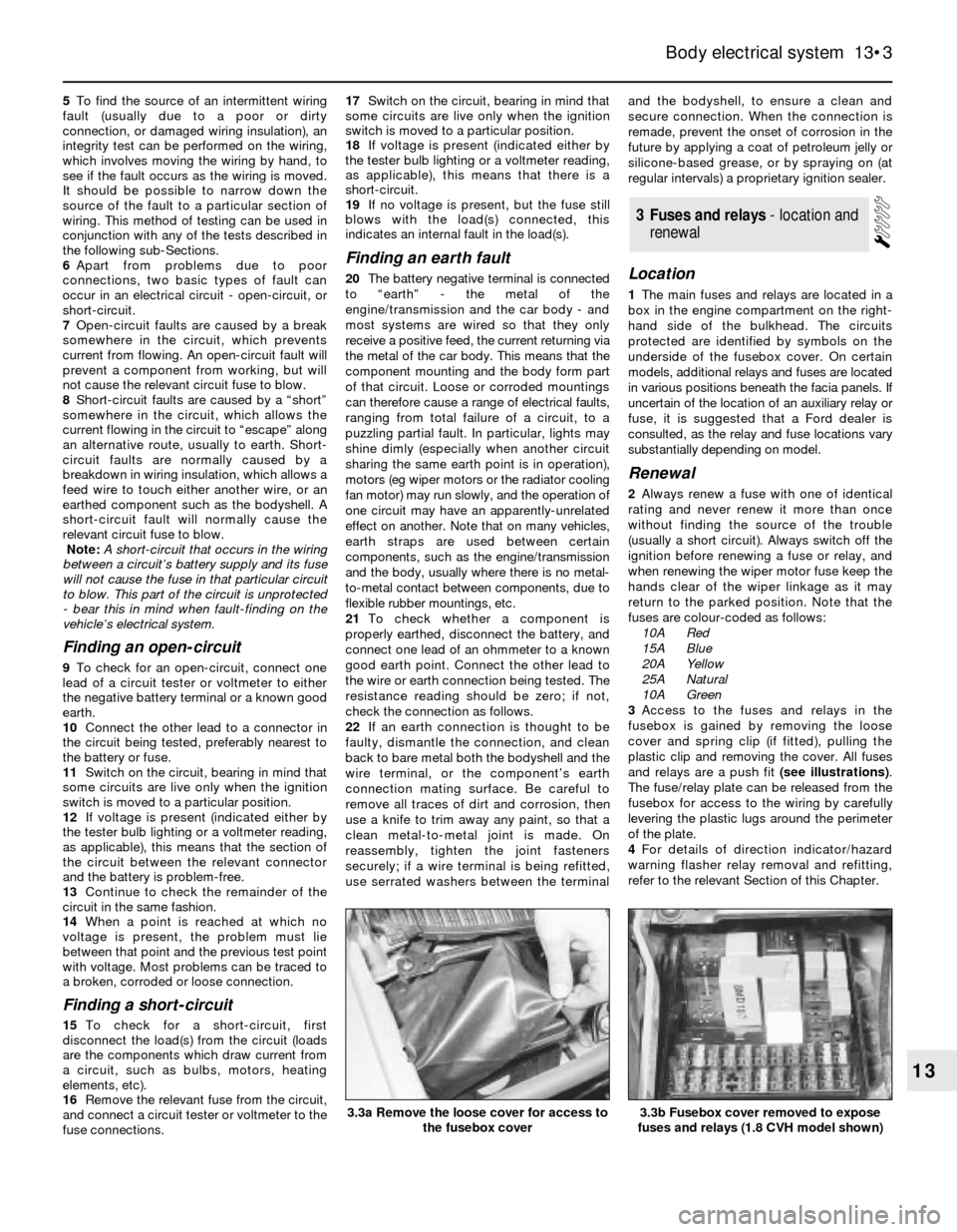
3Access to the fuses and relays in the
fusebox is gained by removing the loose
cover and spring clip (if fitted), pulling the
plastic clip and removing the cover. All fuses
and relays are a push fit (see illustrations).
The fuse/relay plate can be released from the
fusebox for access to the wiring by carefully
levering the plastic lugs around the perimeter
of the plate.
4For details of direction indicator/hazard
warning flasher relay removal and refitting,
refer to the relevant Section of this Chapter.
3Fuses and relays - location and
renewal
Body electrical system 13•3
13
3.3b Fusebox cover removed to expose
fuses and relays (1.8 CVH model shown)3.3a Remove the loose cover for access to
the fusebox cover
Page 6 of 25
7Unclip the switch from the lock assembly,
disconnect the wiring plug and remove the
switch.
8Refitting is a reversal of removal.
1Disconnect the battery negative lead.
2Working inside the vehicle, remove the
handbrake lever rubber gaiter and/or the
centre console, as necessary.
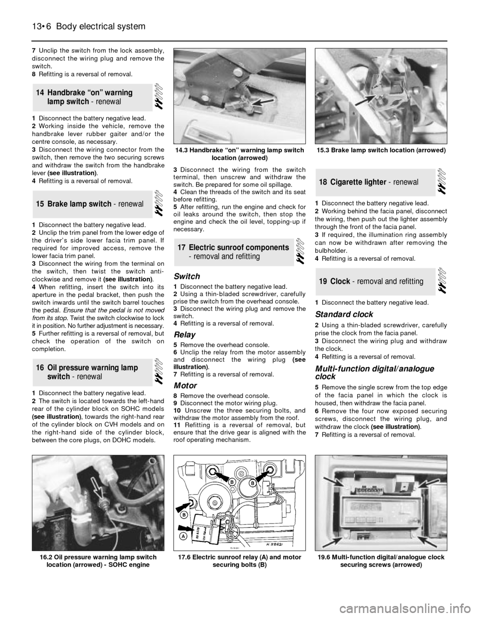
3Disconnect the wiring connector from the
switch, then remove the two securing screws
and withdraw the switch from the handbrake
lever (see illustration).
4Refitting is a reversal of removal.
1Disconnect the battery negative lead.
2Unclip the trim panel from the lower edge of
the driver’s side lower facia trim panel. If
required for improved access, remove the
lower facia trim panel.
3Disconnect the wiring from the terminal on
the switch, then twist the switch anti-
clockwise and remove it (see illustration).
4When refitting, insert the switch into its
aperture in the pedal bracket, then push the
switch inwards until the switch barrel touches
the pedal. Ensure that the pedal is not moved
from its stop. Twist the switch clockwise to lock
it in position. No further adjustment is necessary.
5Further refitting is a reversal of removal, but
check the operation of the switch on
completion.
1Disconnect the battery negative lead.
2The switch is located towards the left-hand
rear of the cylinder block on SOHC models
(see illustration), towards the right-hand rear
of the cylinder block on CVH models and on
the right-hand side of the cylinder block,
between the core plugs, on DOHC models.3Disconnect the wiring from the switch
terminal, then unscrew and withdraw the
switch. Be prepared for some oil spillage.
4Clean the threads of the switch and its seat
before refitting.
5After refitting, run the engine and check for
oil leaks around the switch, then stop the
engine and check the oil level, topping-up if
necessary.
Switch
1Disconnect the battery negative lead.
2Using a thin-bladed screwdriver, carefully
prise the switch from the overhead console.
3Disconnect the wiring plug and remove the
switch.
4Refitting is a reversal of removal.
Relay
5Remove the overhead console.
6Unclip the relay from the motor assembly
and disconnect the wiring plug (see
illustration).
7Refitting is a reversal of removal.
Motor
8Remove the overhead console.
9Disconnect the motor wiring plug.
10Unscrew the three securing bolts, and
withdraw the motor assembly from the roof.
11Refitting is a reversal of removal, but
ensure that the drive gear is aligned with the
roof operating mechanism.1Disconnect the battery negative lead.
2Working behind the facia panel, disconnect
the wiring, then push out the lighter assembly
through the front of the facia panel.
3If required, the illumination ring assembly
can now be withdrawn after removing the
bulbholder.
4Refitting is a reversal of removal.
1Disconnect the battery negative lead.
Standard clock
2Using a thin-bladed screwdriver, carefully
prise the clock from the facia panel.
3Disconnect the wiring plug and withdraw
the clock.
4Refitting is a reversal of removal.
Multi-function digital/analogue
clock
5Remove the single screw from the top edge
of the facia panel in which the clock is
housed, then withdraw the facia panel.
6Remove the four now exposed securing
screws, disconnect the wiring plug, and
withdraw the clock (see illustration).
7Refitting is a reversal of removal.
19Clock - removal and refitting
18Cigarette lighter - renewal
17Electric sunroof components
- removal and refitting
16Oil pressure warning lamp
switch - renewal
15Brake lamp switch - renewal
14Handbrake “on” warning
lamp switch - renewal
13•6Body electrical system
14.3 Handbrake “on” warning lamp switch
location (arrowed)
16.2 Oil pressure warning lamp switch
location (arrowed) - SOHC engine19.6 Multi-function digital/analogue clock
securing screws (arrowed)17.6 Electric sunroof relay (A) and motor
securing bolts (B)
15.3 Brake lamp switch location (arrowed)
Page 7 of 25
Models up to 1992
1Disconnect the battery negative lead.
2Remove the securing screws and unclip the
lower and upper steering column shrouds.
3Where applicable, remove the instrument
panel illumination and intermittent wiper
rheostats.
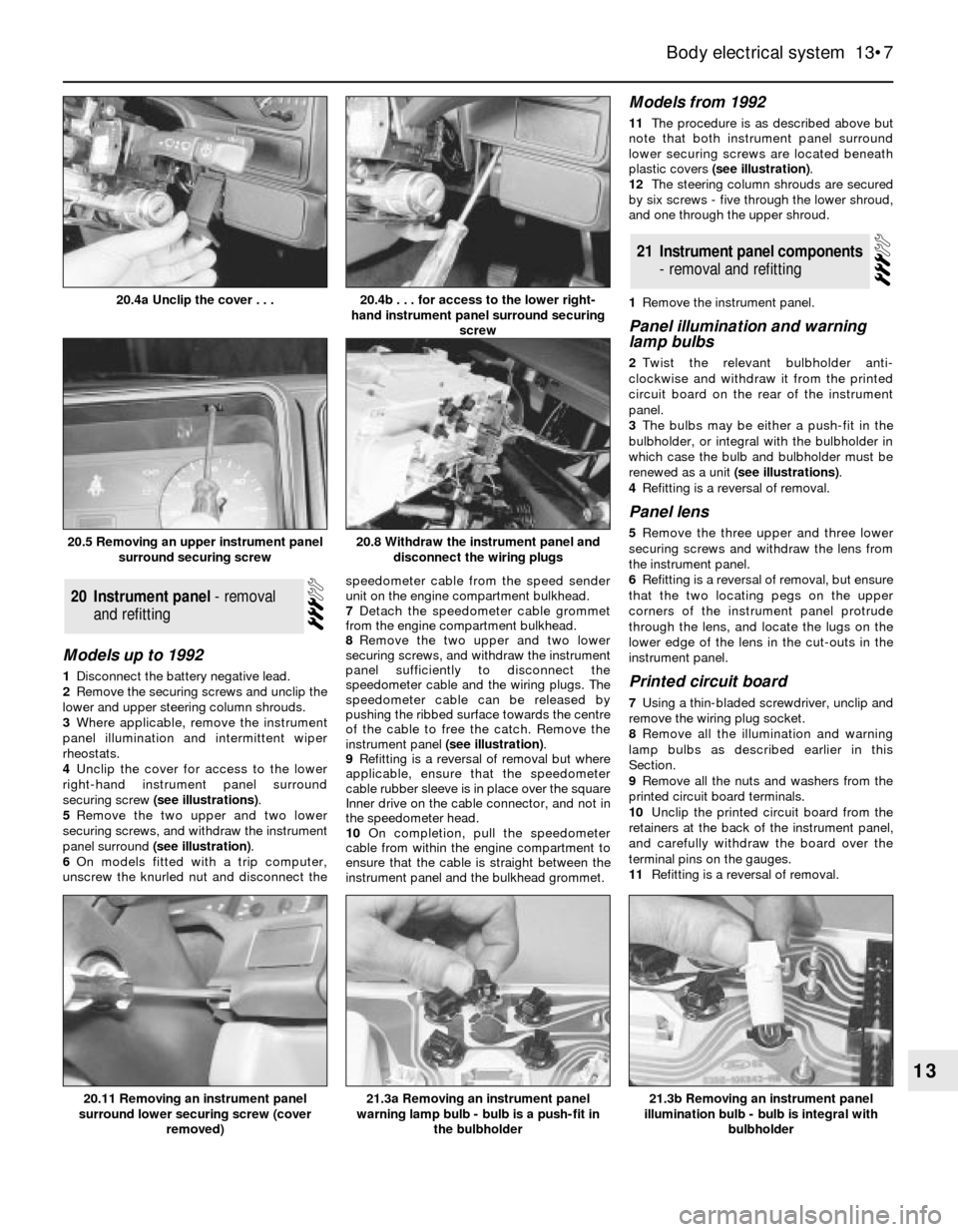
4Unclip the cover for access to the lower
right-hand instrument panel surround
securing screw (see illustrations).
5Remove the two upper and two lower
securing screws, and withdraw the instrument
panel surround (see illustration).
6On models fitted with a trip computer,
unscrew the knurled nut and disconnect thespeedometer cable from the speed sender
unit on the engine compartment bulkhead.
7Detach the speedometer cable grommet
from the engine compartment bulkhead.
8Remove the two upper and two lower
securing screws, and withdraw the instrument
panel sufficiently to disconnect the
speedometer cable and the wiring plugs. The
speedometer cable can be released by
pushing the ribbed surface towards the centre
of the cable to free the catch. Remove the
instrument panel (see illustration).
9Refitting is a reversal of removal but where
applicable, ensure that the speedometer
cable rubber sleeve is in place over the square
Inner drive on the cable connector, and not in
the speedometer head.
10On completion, pull the speedometer
cable from within the engine compartment to
ensure that the cable is straight between the
instrument panel and the bulkhead grommet.
Models from 1992
11The procedure is as described above but
note that both instrument panel surround
lower securing screws are located beneath
plastic covers (see illustration).
12The steering column shrouds are secured
by six screws - five through the lower shroud,
and one through the upper shroud.
1Remove the instrument panel.
Panel illumination and warning
lamp bulbs
2Twist the relevant bulbholder anti-
clockwise and withdraw it from the printed
circuit board on the rear of the instrument
panel.
3The bulbs may be either a push-fit in the
bulbholder, or integral with the bulbholder in
which case the bulb and bulbholder must be
renewed as a unit (see illustrations).
4Refitting is a reversal of removal.
Panel lens
5Remove the three upper and three lower
securing screws and withdraw the lens from
the instrument panel.
6Refitting is a reversal of removal, but ensure
that the two locating pegs on the upper
corners of the instrument panel protrude
through the lens, and locate the lugs on the
lower edge of the lens in the cut-outs in the
instrument panel.
Printed circuit board
7Using a thin-bladed screwdriver, unclip and
remove the wiring plug socket.
8Remove all the illumination and warning
lamp bulbs as described earlier in this
Section.
9Remove all the nuts and washers from the
printed circuit board terminals.
10Unclip the printed circuit board from the
retainers at the back of the instrument panel,
and carefully withdraw the board over the
terminal pins on the gauges.
11Refitting is a reversal of removal.
21Instrument panel components
- removal and refitting
20Instrument panel - removal
and refitting
Body electrical system 13•7
13
20.5 Removing an upper instrument panel
surround securing screw
21.3b Removing an instrument panel
illumination bulb - bulb is integral with
bulbholder21.3a Removing an instrument panel
warning lamp bulb - bulb is a push-fit in
the bulbholder20.11 Removing an instrument panel
surround lower securing screw (cover
removed)
20.8 Withdraw the instrument panel and
disconnect the wiring plugs
20.4b . . . for access to the lower right-
hand instrument panel surround securing
screw20.4a Unclip the cover . . .
Page 8 of 25
Speedometer
12Remove the panel lens (paras. 5 and 6).
13Remove the two screws securing the
speedometer to the rear of the instrument
panel, taking care not to lose the two brushes.
Withdraw the speedometer through the front
of the instrument panel.
14Refitting is a reversal of removal.
Tachometer
Models up to 1990
15Remove the four or five securing screws,
as applicable, and separate the two halves of
the instrument panel housing.
16Remove the three securing nuts and
washers from the rear of the instrument panel
housing, and withdraw the tachometer.
17Refitting is a reversal of removal, but ensure
that the tachometer engages with the locating
ribs in the housing around the dial edge.
Models from 1990
18The procedure is as described above but
before the tachometer can be withdrawn from
the instrument panel housing, the printed circuit
board must be carefully pulled from the
tachometer terminals. Ensure that the printed
circuit board is pushed fully home when refitting.
Fuel and temperature gauges
Models up to 1987
19Remove the four securing screws and
separate the two halves of the instrument
panel housing.
20Remove the four securing nuts and washers
from the rear of the instrument panel housing,
and withdraw the combined gauge assembly.
21Refitting is a reversal of removal.
Models from 1987
22Remove the five securing screws and
separate the two halves of the instrument
panel housing.
23Remove the printed circuit board as
described previously in this Section.
24On “low specification” models, remove the
two securing screws from the front of the
gauge assembly, then withdraw the combined
gauge assembly from the printed circuit board.25On “high specification” models, simply
withdraw the combined gauge assembly from
the printed circuit board.
26Refitting is a reversal of removal, but on
“high specification” models, ensure that the
gauge assembly engages with the locating
ribs in the housing around the gauge edge.
1Disconnect the battery negative lead
Computer module
2Remove the single screw from the top edge
of the facia panel in which the module is
housed, then withdraw the facia panel.
3Remove the four now exposed securing
screws, disconnect the wiring plug, and
carefully withdraw the module. On later
models a retaining lug must be depressed
before the wiring plug can be disconnected.
4Where applicable, the mounting brackets
can be removed from the module by
unscrewing the securing nuts.
5If necessary, the illumination bulb can be
removed from the module by twisting the
bulbholder anti-clockwise using a pair of long-
nosed pliers. The bulb is a push-fit in the holder.
6Refitting is a reversal of removal.
Speed sender unit
Models up to 1987
7The speed sender unit is located in the
engine compartment on the right-hand side of
the bulkhead.
8Disconnect the plug from the sender unit.
9Unscrew the two knurled nuts from the
sender unit and disconnect the two
speedometer cables.
10Remove the three securing screws and
remove the bracket and sender unit.
11Unscrew and remove the securing nut
and washer, and separate the sender unit
from the bracket.
12Refitting is a reversal of removal.
Models from 1987
13Detach the wiring, hose retainers andcover panel from the bulkhead to gain access
to the sender unit.
14Proceed as shown in paragraphs 7 to 9.
15Remove the retaining nut and washer and
withdraw the sender unit.
16Refitting is a reversal of removal.
Fuel flow sensor unit
Carburettor models
17The fuel flow sensor is located on the left-
hand side of the engine compartment (see
illustration).
18Disconnect the wiring plug from the
sensor unit.
19Refer to the “Safety first!” Section at the
front of the manual, and the precautions in
Chapter 4, then disconnect the fuel pipes from
the sensor unit. Note that on models up to
1987 there are three fuel pipe connections, and
on models from 1987 there are two fuel pipe
connections. Be prepared for fuel spillage.
20Remove the three securing screws and
withdraw the bracket and sender unit.
21Unscrew the four nuts and separate the
sender unit from the bracket.
22Refitting is a reversal of removal, but
ensure that the flow direction arrows on the
fuel inlet and outlet ports are correctly
orientated, and that the arrow on the rear of
the unit points to the top.
Fuel injection models
23The sensor is located on the left-hand
side of the engine compartment.
24Disconnect the wiring plug from the
sensor unit.
25Refer to the “Safety first!” Section at the
front of the manual, and the precautions in
Chapter 4, then unscrew the two union nuts
and disconnect the fuel pipes from the sensor
unit. Be prepared for fuel spillage.
26Remove the two securing screws and
withdraw the sensor unit.
27Refitting is a reversal of removal, but
ensure that the No 2 injector fuel pipe is fitted
to the sensor unit outlet port marked with an
arrow, and ensure that the union washers are
in place (see illustration). Tighten the fuel
pipe unions to the specified torque.
22Trip computer components -
removal and refitting
13•8Body electrical system
22.17 Trip computer fuel flow sensor unit location - carburettor
models up to 1987. Bracket retaining screws arrowed
22.27 Trip computer fuel flow sensor unit - fuel injection models
A Wiring plug
B Hollow bolts
C Inlet port banjo connectorD Bracket
E Outlet port banjo connector
F Sensor unit
Page 9 of 25
Location
1The AWS control unit, and (when fitted) the
bulb failure monitor, are located behind the
glovebox on models up to 1987.
2On models from 1987, the control and bulb
failure modules are located behind the driver’s
side footwell trim panel.
Testing
3Thorough testing and fault finding should
be left to a Ford dealer or other electrical
specialist, having test equipment. Unskilled or
uninformed testing may cause damage.
4Investigation of malfunctions should begin
by checking that all wiring is intact and
securely connected. If checking wires or
sensors for continuity, always disconnect the
control unit and/or bulb failure monitor before
so doing, otherwise damage may be caused.
5Note that false oil level readings can result if
the car is parked on a slope. False bulb failure
warnings may occur if incorrect wattage bulbs
are fitted.
Removal and refitting
6Disconnect the battery negative lead.
Warning lamp bulbs
7Remove the single screw from the top edge
of the facia panel in which the warning lamps
are housed, then withdraw the facia panel
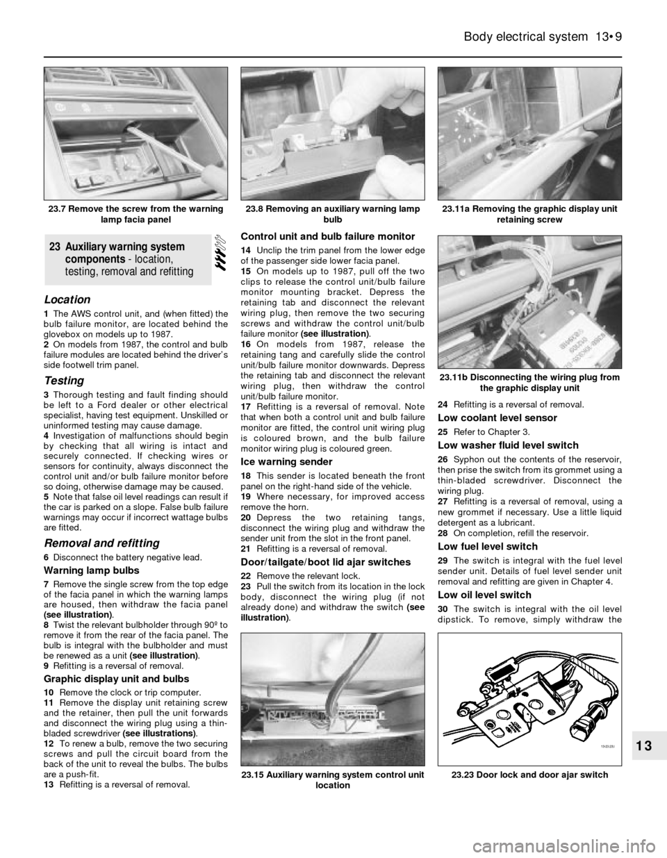
(see illustration).
8Twist the relevant bulbholder through 90º to
remove it from the rear of the facia panel. The
bulb is integral with the bulbholder and must
be renewed as a unit (see illustration).
9Refitting is a reversal of removal.
Graphic display unit and bulbs
10Remove the clock or trip computer.
11Remove the display unit retaining screw
and the retainer, then pull the unit forwards
and disconnect the wiring plug using a thin-
bladed screwdriver (see illustrations).
12To renew a bulb, remove the two securing
screws and pull the circuit board from the
back of the unit to reveal the bulbs. The bulbs
are a push-fit.
13Refitting is a reversal of removal.
Control unit and bulb failure monitor
14Unclip the trim panel from the lower edge
of the passenger side lower facia panel.
15On models up to 1987, pull off the two
clips to release the control unit/bulb failure
monitor mounting bracket. Depress the
retaining tab and disconnect the relevant
wiring plug, then remove the two securing
screws and withdraw the control unit/bulb
failure monitor (see illustration).
16On models from 1987, release the
retaining tang and carefully slide the control
unit/bulb failure monitor downwards. Depress
the retaining tab and disconnect the relevant
wiring plug, then withdraw the control
unit/bulb failure monitor.
17Refitting is a reversal of removal. Note
that when both a control unit and bulb failure
monitor are fitted, the control unit wiring plug
is coloured brown, and the bulb failure
monitor wiring plug is coloured green.
Ice warning sender
18This sender is located beneath the front
panel on the right-hand side of the vehicle.
19Where necessary, for improved access
remove the horn.
20Depress the two retaining tangs,
disconnect the wiring plug and withdraw the
sender unit from the slot in the front panel.
21Refitting is a reversal of removal.
Door/tailgate/boot lid ajar switches
22Remove the relevant lock.
23Pull the switch from its location in the lock
body, disconnect the wiring plug (if not
already done) and withdraw the switch (see
illustration).24Refitting is a reversal of removal.
Low coolant level sensor
25Refer to Chapter 3.
Low washer fluid level switch
26Syphon out the contents of the reservoir,
then prise the switch from its grommet using a
thin-bladed screwdriver. Disconnect the
wiring plug.
27Refitting is a reversal of removal, using a
new grommet if necessary. Use a little liquid
detergent as a lubricant.
28On completion, refill the reservoir.
Low fuel level switch
29The switch is integral with the fuel level
sender unit. Details of fuel level sender unit
removal and refitting are given in Chapter 4.
Low oil level switch
30The switch is integral with the oil level
dipstick. To remove, simply withdraw the
23Auxiliary warning system
components - location,
testing, removal and refitting
Body electrical system 13•9
13
23.11a Removing the graphic display unit
retaining screw
23.23 Door lock and door ajar switch23.15 Auxiliary warning system control unit
location
23.11b Disconnecting the wiring plug from
the graphic display unit
23.8 Removing an auxiliary warning lamp
bulb23.7 Remove the screw from the warning
lamp facia panel
Page 10 of 25
dipstick from its tube and disconnect the
wiring plug.
31Refitting is a reversal of removal.
1Remove the instrument panel.
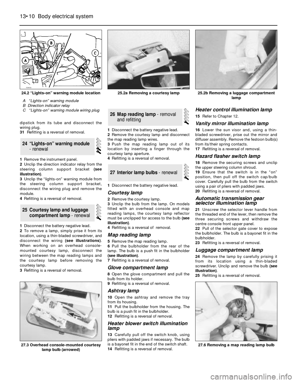
2Unclip the direction indicator relay from the
steering column support bracket (see
illustration).
3Unclip the “lights-on” warning module from
the steering column support bracket,
disconnect the wiring plug and remove the
module.
4Refitting is a reversal of removal.
1Disconnect the battery negative lead.
2To remove a lamp, simply prise it from its
location, using a thin-bladed screwdriver, and
disconnect the wiring (see illustrations).
When working on an overhead console-
mounted courtesy lamp, disconnect the
wiring between the map reading lamps and
the courtesy lamp before removing the
courtesy lamp.
3Refitting is a reversal of removal.1Disconnect the battery negative lead.
2Remove the courtesy lamp and disconnect
the map reading lamp wires.
3Push the map reading lamp out of its
location by inserting a finger through the
courtesy lamp aperture.
4Refitting is a reversal of removal.
1Disconnect the battery negative lead.
Courtesy lamp
2Remove the courtesy lamp.
3Unclip the bulb from the lamp. On models
fitted with an overhead console and map
reading lamps, the courtesy lamp reflector
must be unclipped for access to the bulb (see
illustration).
4Refitting is a reversal of removal.
Map reading lamp
5Remove the map reading lamp.
6Pull the bulbholder from the rear of the
lamp. The bulb is a push fit in the bulbholder
(see illustration).
7Refitting is a reversal of removal.
Glove compartment lamp
8Open the glove compartment and pull the
bulb from its holder.
9Refitting is a reversal of removal.
Ashtray lamp
10Open the ashtray and remove the tray
from its housing.
11Pull the bulbholder from the housing. The
bulb is a push fit in the bulbholder.
12Refitting is a reversal of removal.
Heater blower switch illumination
lamp
13Carefully pull off the switch knob, using
pliers with padded jaws if necessary. The bulb
is a bayonet fit in the end of the switch shaft.
14Refitting is a reversal of removal.
Heater control illumination lamp
15Refer to Chapter 12.
Vanity mirror illumination lamp
16Lower the sun visor and, using a thin-
bladed screwdriver, prise out the mirror and
diffuser assembly. Remove the festoon bulb(s)
from its/their spring contacts.
17Refitting is a reversal of removal.
Hazard flasher switch lamp
18Remove the securing screws and unclip
the upper steering column shroud.
19Ensure that the switch is in the “on”
position, then pull off the switch cap/bulb
cover. Carefully pull the bulb from the switch
using a pair of pliers with padded jaws.
20Refitting is a reversal of removal.
Automatic transmission gear
selector illumination lamp
21Unscrew the selector lever handle from
the threaded end of the lever, then remove the
three securing screws and withdraw the
centre console front upper panel.
22Pull of the selector gate cover to expose
the bulbholder. The bulb is a bayonet fit in the
bulbholder.
23Refitting is a reversal of removal.
Luggage compartment lamp
24Remove the lamp by carefully prising it
from its location using a thin-bladed
screwdriver. Unclip and remove the bulb (see
illustration).
25Refitting is a reversal of removal.
27Interior lamp bulbs - renewal
26Map reading lamp - removal
and refitting
25Courtesy lamp and luggage
compartment lamp - renewal
24“Lights-on” warning module
- renewal
13•10Body electrical system
24.2 “Lights-on” warning module location
A “Lights-on” warning module
B Direction indicator relay
C “Lights-on” warning module wiring plug
25.2b Removing a luggage compartment
lamp
27.6 Removing a map reading lamp bulb27.3 Overhead console-mounted courtesy
lamp bulb (arrowed)
25.2a Removing a courtesy lamp
Page 11 of 25
Clock illumination lamp
26Remove the clock.
27The bulb is a bayonet fit in the rear of the
clock.
28Refitting is a reversal of removal.
1Disconnect the battery negative lead.
Removal and refitting
2Detach the wiring connector at the left-hand
bonnet hinge, and attach a length of string to
the end of the wire running from the lamp.
3If necessary, remove the underbonnet
insulation by prising out the two-piece plastic
securing clips, then working at the lamp, pull the
wiring and the string through the bonnet panel.
4Detach the string from the end of the wire,
and remove the screw securing the lamp to
the bonnet. Withdraw the lamp.
5Commence refitting by attaching the end of
the wiring to the string, and pulling the string
and wiring through the bonnet panel. Further
refitting is a reversal of removal.
Bulb renewal
6Simply press and twist the bulb to remove it
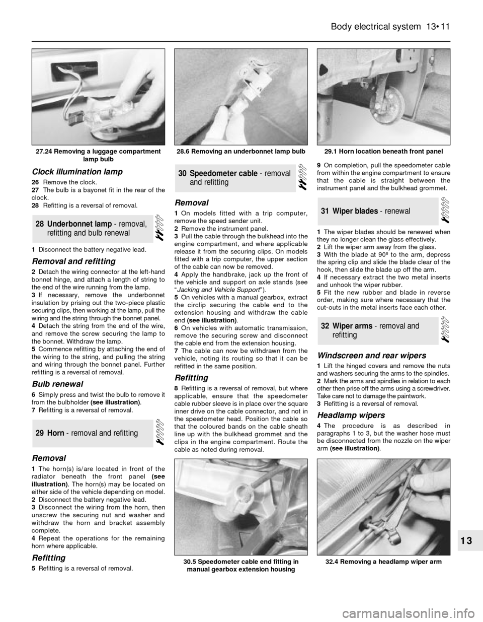
from the bulbholder (see illustration).
7Refitting is a reversal of removal.
Removal
1The horn(s) is/are located in front of the
radiator beneath the front panel (see
illustration). The horn(s) may be located on
either side of the vehicle depending on model.
2Disconnect the battery negative lead.
3Disconnect the wiring from the horn, then
unscrew the securing nut and washer and
withdraw the horn and bracket assembly
complete.
4Repeat the operations for the remaining
horn where applicable.
Refitting
5Refitting is a reversal of removal.
Removal
1On models fitted with a trip computer,
remove the speed sender unit.
2Remove the instrument panel.
3Pull the cable through the bulkhead into the
engine compartment, and where applicable
release it from the securing clips. On models
fitted with a trip computer, the upper section
of the cable can now be removed.
4Apply the handbrake, jack up the front of
the vehicle and support on axle stands (see
“Jacking and Vehicle Support”).
5On vehicles with a manual gearbox, extract
the circlip securing the cable end to the
extension housing and withdraw the cable
end (see illustration).
6On vehicles with automatic transmission,
remove the securing screw and disconnect
the cable end from the extension housing.
7The cable can now be withdrawn from the
vehicle, noting its routing so that it can be
refitted in the same position.
Refitting
8Refitting is a reversal of removal, but where
applicable, ensure that the speedometer
cable rubber sleeve is in place over the square
inner drive on the cable connector, and not in
the speedometer head. Position the cable so
that the coloured bands on the cable sheath
line up with the bulkhead grommet and the
clips in the engine compartment. Route the
cable as noted during removal.9On completion, pull the speedometer cable
from within the engine compartment to ensure
that the cable is straight between the
instrument panel and the bulkhead grommet.
1The wiper blades should be renewed when
they no longer clean the glass effectively.
2Lift the wiper arm away from the glass.
3With the blade at 90º to the arm, depress
the spring clip and slide the blade clear of the
hook, then slide the blade up off the arm.
4If necessary extract the two metal inserts
and unhook the wiper rubber.
5Fit the new rubber and blade in reverse
order, making sure where necessary that the
cut-outs in the metal inserts face each other.
Windscreen and rear wipers
1Lift the hinged covers and remove the nuts
and washers securing the arms to the spindles.
2Mark the arms and spindles in relation to each
other then prise off the arms using a screwdriver.
Take care not to damage the paintwork.
3Refitting is a reversal of removal.
Headlamp wipers
4The procedure is as described in
paragraphs 1 to 3, but the washer hose must
be disconnected from the nozzle on the wiper
arm (see illustration).
32Wiper arms - removal and
refitting
31Wiper blades - renewal
30Speedometer cable - removal
and refitting
29Horn - removal and refitting
28Underbonnet lamp - removal,
refitting and bulb renewal
Body electrical system 13•11
13
29.1 Horn location beneath front panel
30.5 Speedometer cable end fitting in
manual gearbox extension housing
28.6 Removing an underbonnet lamp bulb27.24 Removing a luggage compartment
lamp bulb
32.4 Removing a headlamp wiper arm
Page 14 of 25
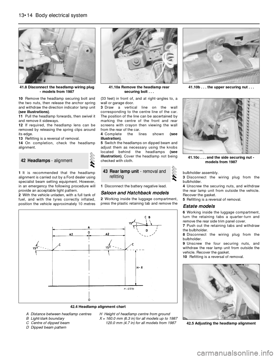
10Remove the headlamp securing bolt and
the two nuts, then release the anchor spring
and withdraw the direction indicator !amp unit
(see illustrations).
11Pull the headlamp forwards, then swivel it
and remove it sideways.
12If required, the headlamp lens can be
removed by releasing the spring clips around
its edge.
13Refitting is a reversal of removal.
14On completion, check the headlamp
alignment.
1It is recommended that the headlamp
alignment is carried out by a Ford dealer using
specialist beam setting equipment. However,
in an emergency the following procedure will
provide an acceptable light pattern.
2With the vehicle unladen, with a full tank of
fuel, and with the tyres correctly inflated,
position the vehicle approximately 10 metres(33 feet) in front of, and at right-angles to, a
wall or garage door.
3Draw a vertical line on the wall
corresponding to the centre line of the car.
The position of the line can be ascertained by
marking the centre of the front and rear
screens with crayon then viewing the wall
from the rear of the car.
4Complete the lines shown (see
illustration).
5Switch the headlamps on dipped beam and
adjust them as necessary using the knobs
located behind the headlamps (see
illustration). Cover the headlamp not being
checked with cloth.
1Disconnect the battery negative lead.
Saloon and Hatchback models
2Working inside the luggage compartment,
press the plastic retaining tab and remove thebulbholder assembly.
3Disconnect the wiring plug from the
bulbholder.
4Unscrew the securing nuts, and withdraw
the rear lamp unit from outside the vehicle.
Recover the gasket.
5Refitting is a reversal of removal.
Estate models
6Working inside the luggage compartment,
turn the retaining tabs a quarter-turn and
remove the rear side trim panel cover.
7Push out the retaining tabs and withdraw
the bulbholder.
8Disconnect the wiring plug from the
bulbholder.
9Unscrew the four securing nuts, and
withdraw the rear lamp unit from outside the
vehicle. Recover the gasket.
10Refitting is a reversal of removal.
43Rear lamp unit - removal and
refitting
42Headlamps - alignment
13•14Body electrical system
41.8 Disconnect the headlamp wiring plug
- models from 198741.10b . . . the upper securing nut . . .
42.5 Adjusting the headlamp alignment
42.4 Headlamp alignment chart
A Distance between headlamp centres
B Light/dark boundary
C Centre of dipped beam
D Dipped beam patternH Height of headlamp centre from ground
X = 160.0 mm (6.3 in) for all models up to 1987
120.0 mm (4.7 in) for all models from 1987
41.10c . . . and the side securing nut -
models from 1987
41.10a Remove the headlamp rear
securing bolt . . .